EP0832418B1 - Detection optique sensible et a reponse rapide de mouvement transitoire d'une surface de dispersion au moyen d'un melange a deux ondes - Google Patents
Detection optique sensible et a reponse rapide de mouvement transitoire d'une surface de dispersion au moyen d'un melange a deux ondes Download PDFInfo
- Publication number
- EP0832418B1 EP0832418B1 EP97919218A EP97919218A EP0832418B1 EP 0832418 B1 EP0832418 B1 EP 0832418B1 EP 97919218 A EP97919218 A EP 97919218A EP 97919218 A EP97919218 A EP 97919218A EP 0832418 B1 EP0832418 B1 EP 0832418B1
- Authority
- EP
- European Patent Office
- Prior art keywords
- real
- holographic material
- time
- received light
- time holographic
- Prior art date
- Legal status (The legal status is an assumption and is not a legal conclusion. Google has not performed a legal analysis and makes no representation as to the accuracy of the status listed.)
- Expired - Lifetime
Links
Images

Classifications
-
- G—PHYSICS
- G01—MEASURING; TESTING
- G01B—MEASURING LENGTH, THICKNESS OR SIMILAR LINEAR DIMENSIONS; MEASURING ANGLES; MEASURING AREAS; MEASURING IRREGULARITIES OF SURFACES OR CONTOURS
- G01B9/00—Measuring instruments characterised by the use of optical techniques
- G01B9/02—Interferometers
- G01B9/021—Interferometers using holographic techniques
- G01B9/027—Interferometers using holographic techniques in real time
-
- G—PHYSICS
- G01—MEASURING; TESTING
- G01P—MEASURING LINEAR OR ANGULAR SPEED, ACCELERATION, DECELERATION, OR SHOCK; INDICATING PRESENCE, ABSENCE, OR DIRECTION, OF MOVEMENT
- G01P3/00—Measuring linear or angular speed; Measuring differences of linear or angular speeds
- G01P3/36—Devices characterised by the use of optical means, e.g. using infrared, visible, or ultraviolet light
- G01P3/366—Devices characterised by the use of optical means, e.g. using infrared, visible, or ultraviolet light by using diffraction of light
Definitions
- the invention generally relates to a method and apparatus for optically detecting transient motion from a scattering surface. More particularly, the invention relates toward detecting optical phase modulations such as those produced by ultrasound .
- phase modulation or frequency modulation of an optical wave is important for various fields of application where optical beams are used to detect the motion of objects.
- This is the case of laser sensing of vibrations and laser detection of ultrasound and of transient body deformations such as those produced by a shock or impact.
- ultrasound or a shock wave is generated by a laser.
- a completely remote ultrasonic inspection system can be realized, permitting for example ultrasonic probing at elevated temperatures.
- a technique based on laser generation and optical detection can thus be advantageously used to inspect materials at high temperatures (such as all metals and ceramics) for process and quality control, to detect flaws as soon as they are created during processing, to measure production parameters such as thickness, temperature, etc. and to determine microstructural properties on-line (grain size, porosity, etc.)
- This technique is also particularly advantageous to inspect parts of complex shapes such as those made of polymer matrix composite materials and used in advanced aeronautic and aerospace structures.
- This étendue parameter (or throughput), is defined as the product of its effective entrance aperture area by the solid angle limited by the rays of maximum inclination passing through the entrance aperture center and thus defining the field of view.
- the maximum inclination rays can be defined as those which produce a shift of the interference pattern by a quarter of a fringe.
- the importance of the étendue parameter stems from its invariance within the frame of geometric optics. A large étendue permits to choose light collecting optics of large size, being only limited by cost and practical feasibility, and to detect surface motion over a large area.
- Photorefractive crystals are holographic optical materials in which the light grating produced by the interference of the signal wave (having the phase change given by the surface motion) with a pump wave directly derived from the laser gives rise to a space charge grating, following the motion of free charges within the material.
- This space charge grating gives in turn rise by the electrooptic effect to an index of refraction grating.
- This grating which is quasi-stationary during the surface motion, diffracts the pump beam directly derived from the laser to produce a wave propagating in the direction of the signal beam, with a wavefront matched to it. Therefore, this two-wave mixing scheme could also be viewed as real-time holography, the reading of the hologram created inside the material being performed simultaneously to its writing.
- the diffracted wave acts as the reference beam of an interferometer and its interference with the transmitted signal beam provides an intensity modulated signal representative of the transient phase variation produced by the workpiece surface motion.
- This principle can also be applied in real-time holographic materials in which gratings that are not index of refraction gratings, such as absorption gratings, are produced. It can also be applied in amorphous materials such as photorefractive polymers.
- Two-wave mixing in a real-time holographic material or photorefractive crystal is an attractive approach to perform the detection of transient surface motion, which provides in particular a more compact system than the ones based on the Fabry-Perot interferometer.
- Two-wave mixing allows also a broader detection bandwidth than the Fabry-Perot based systems, especially including the low ultrasonic frequency range, from several kHz to about 1 MHz.
- the formation and erasure of the photorefractive grating have to be sufficiently slow for satisfactory operation of the device, they are often much too slow for adequate adaptation to variations of the speckle pattern. This is the case of many applications where the probed surface is affected by vibrations or is moving or when the inspected location is changed.
- the application of an electric field has the effect of not only increasing the amplitude of the diffracted beam, but also of shifting the index of refraction grating with respect to the interference grating, so the transmitted signal wave and the diffracted reference wave are not in phase. With a sufficient applied field, it is possible to get close to the optimum condition of quadrature. Note also that the application of an electric field tends also to lengthen the response time. Furthermore, this principle has been applied to the detection of ultrasound using a BSO crystal and that work was reported in Japanese Journal of Applied Physics, vol. 34, pp. 3737-3740, 1995, title :" Optical measurement of ultrasonic nanometer motion of rough surface by two-wave mixing in BSO", authors : Tokuyuki Honda, Toshihisa Yamashita and Hirokazu Matsumoto.”
- a method of optically detecting transient motion from the surface of a workpiece having a predetermined duration comprising the steps of:
- an apparatus for optically detecting transient motion from the surface of a workpiece having a predetermined duration which comprises:
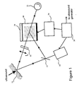
- FIG. 1 illustrates a first embodiment according to the invention.
- a laser 10 is used to illuminate the workpiece 14 whose surface is in transient motion, for example, excited by ultrasound.
- Part of the laser light scattered or reflected by the surface of the workpiece is collected by a lens system L and then projected onto a real-time holographic material, preferably in the form of a photorefractive crystal 18.
- a fraction of the laser beam is removed at the output of the laser (pump beam) by a beam splitter 12 and is sent onto the real-time holographic material element 18 where it interferes with the beam collected from the surface (signal beam) to produce an interference grating and then an index of refraction grating or absorption grating, from which a reference wave is produced, as explained above.
- This reference wave produces by interference with the transmitted signal wave an intensity modulated signal representative of the surface motion, which finally appears on a photodetector 22 at the output of the real-time holographic material element 18.
- the voltage is applied only during the time necessary for the detection of the surface transient or ultrasonic motion.
- electronic circuitry 26 is used to generate a clock signal and to command the turn-on and turn-off of the high voltage source 24 (typically several kV), whose output is connected to electrodes on the real-time holographic material element or crystal 18. Typically a turn-on interval of about 100 ⁇ s is used and is sufficient to capture the ultrasonic signal of interest.
- This clock and trigger electronics 26 is also used to trigger the ultrasonic generation device after the turn-on of the high voltage source.
- the ultrasonic generation device is usually in cases of practical interest a laser, but others means such as piezoelectric devices could be used as well.
- a fast real-time holographic element 18 is used.
- This element 18 can be in the form of a crystal of the sillenite type such as BSO, BGO or BTO or preferably, a semiconductor photorefractive crystal.
- a crystal such as Indium Phosphide (InP) with iron doping and Cadmium Telluride (CdTe) with vanadium doping was found to be suitable.
- the length of the real-time holographic element or crystal 18 was chosen in such a way as to obtain an optimum sensitivity for a maximum acceptable applied voltage.
- sufficient pump beam illumination is applied to the real-time holographic element to increase its photoconductivity and to decrease its response time.
- the use of a continuous laser may be adequate. Otherwise a pulse system is used to provide a much higher intensity.
- this laser system is triggered by the clock and trigger electronics 26 after the turn-on of the applied voltage and before the ultrasound generation source.
- several hundred watts are sent onto the real-time holographic element providing illumination in the range of 1 kW/cm 2 .
- the real-time holographic element 18 is mounted on a thermoelectric cooler 20 to avoid any temperature run-off or is, alternatively, properly heat-sunk.
- a polarizer 16 may be added on the signal beam path to select the same polarization as that of the pump beam, which is usually polarized. Nevertheless, interference occurs only between beams of the same polarization.
- the polarizer 16 removes light which is not useful and will be collected by the detector, thus adding noise.
- Such polarizer will be added in particular when light is collected from the workpiece 14 and then transmitted to the real-time holographic element using a large core multimode fiber (not represented in Figure 1). In this case, there is near complete depolarization after propagation through the fiber.
- a suitable arrangement is the following : the crystal is cut along the [001], [-110] and [110] faces, the input face is [-110], the signal and pump beams propagate in the [110] plane, are both polarized along the [110] direction, the space charge field and the applied field are both along the [001] direction (the electrodes are on the [001] faces).
- Figure 2 illustrates a second embodiment according to the invention.
- the real-time holographic element 18 again preferably in the form of but not limited to a photorefractive crystal is used in a configuration such that the pump beam is diffracted with a polarization perpendicular to the transmitted signal beam (anisotropic diffraction).
- the crystal has the same cut as before (along the [001], [-110] and [110] faces) and the input face is [-110], as is previously described, the signal and pump beams propagate in the [001] plane and are both polarized along the [001] direction, the space charge field and the applied field are both along the [110] direction (the electrodes are on the [110] faces).
- the polarization direction at the output of the laser 10 and given by the polarizer ahead of the crystal 16 is assumed to be perpendicular to the plane of the drawing.
- the diffracted pump beam (reference beam) and the transmitted signal beam are made to interfere along the two polarizations directions of a polarizing beam splitter PBS oriented at 45° to the plane of the drawing.
- the optical signals along the two polarizations of the polarizing beam splitter PBS are collected by two detectors 30 and 32 whose outputs are sent to a differential amplifier 34. Since the varying parts of these two signals have opposite signs, this configuration allows to increase the sensitivity with respect to the case where only one detector would be used.
- This embodiment is particularly useful when the high repetition rate of the laser combined with high intensity pump beam necessary to get a very short response time limits the applied electric field, so the optimum sensitivity cannot be reached with a crystal 18 of reasonable length in the case of the first embodiment.
- the phase shift can be properly set by the adjustable wave plate 36 shown in Figure 2.
- the additional phase shift given by the wave plate is varied in order to maximize the signal representative of the surface motion. Plate neutral axes are in the plane of the drawing and perpendicular to it.
- a suitable adjustable wave plate 36 is a Babinet-Soleil compensator. Other features of this embodiment are the same as the previous one.
- This embodiment is also useful to minimize the background signal level by its differential configuration and consequently minimizes the effect of laser intensity fluctuations. These intensity fluctuations may fall within the detection bandwidth and may add noise to the output signal. When the quadrature condition between the output signal beam and the reference beam could be reached (in this case the additional phase shift is zero and the adjustable wave plate is not necessary), the output background level is zero and there is complete elimination of the effect of the laser intensity fluctuations on the output signal.
- the embodiment shown in Figure 2 has also the advantage to minimize by its differential configuration, the spurious background coming from scattering or weak reflections by faces of the real-time holographic element or crystal of the strong pump beam.
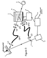
- FIG. 3 illustrates a third preferred embodiment according to the invention.
- the real-time holographic element or photorefractive crystal 18 and its associated optics and detectors can be located at a distance from the detection laser by the use of optical fiber links.
- the first one which includes large core size multimode fiber OF1, lens L1 to collect the scattered light from the surface and lens L2 to project the signal beam onto the real-time holographic material element or photorefractive crystal 18 has been previously reported and used.
- a polarizer P1 is used to select the proper polarization for coupling into the real-time holographic element or crystal.
- the second fiber link for the pump beam is novel. Usually the pump beam is directly derived from the laser and is in good approximation a plane wave.
- a pump beam coupled through a multimode fiber thus producing a speckle-like distribution, works also quite well.
- a fraction of the laser light is coupled into fiber OF2 by lens L3.
- Lens L4 projects transmitted light onto the real-time holographic element or crystal. This light is polarized by polarizer P2.
- polarizer P2 As shown in Figure 3, a single detector 22 can be used similar to the first described embodiment. It is also possible to use a differential scheme as in the second embodiment. In this case the polarizations chosen and the crystal orientation are those indicated above in relation to this second embodiment.
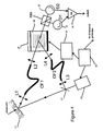
- FIG. 4 illustrates a fourth embodiment according to the invention. Unlike the previous embodiments, this embodiment uses both polarizations of the signal beam.
- the real-time holographic element or crystal 18 has the same orientation as in the second embodiment.
- the signal and the pump beam are coupled onto the real-time holographic element through optical fibers as in the previous embodiment, but no polarizers are used at the output of the fibers.
- These fibers are large core multimode fibers giving speckle-like light without any preferential direction of polarization, i.e. unpolarized light.
- a polarizing beam splitter (PBS) oriented at 45° with respect to the plane of the drawing is used.
- the two signals after the polarizing beam splitter are collected by two detectors 30 and 32 followed by a differential amplifier 34.
- the output signal results from contributions of both polarizations of the fibers and since the available light power is used more efficiently an improved sensitivity could result.
- PBS polarizing beam splitter
- the operation of the device in this case can be understood as follows.
- the application of the electric field produces two new neutral axes at 45° with respect to the plane of the drawing.
- the beams from the signal and pump fibers being unpolarized can be considered as the superposition of two incoherent beams with polarizations along each of the new neutral axes and with approximately the same intensity. These beams give rise to index of refraction gratings, which can be shown to be of opposite signs. Two signals representative of the surface motion with opposite signs are then produced, which add up when the differential configuration shown in Figure 4 is used.
Landscapes
- Physics & Mathematics (AREA)
- General Physics & Mathematics (AREA)
- Engineering & Computer Science (AREA)
- Electromagnetism (AREA)
- Power Engineering (AREA)
- Investigating Or Analyzing Materials By The Use Of Ultrasonic Waves (AREA)
- Length Measuring Devices By Optical Means (AREA)
- Measurement Of Mechanical Vibrations Or Ultrasonic Waves (AREA)
- Instruments For Measurement Of Length By Optical Means (AREA)
- Investigating Or Analysing Materials By Optical Means (AREA)
Claims (23)
- Procédé de détection optique d'un mouvement transitoire par rapport à la surface d'une pièce et ayant une durée prédéterminée, comprenant les étapes consistant à :a) diriger un faisceau, produit par un laser, vers ladite surface ;b) recevoir un faisceau lumineux, qui a été réfléchi ou diffusé par ladite surface ;c) laisser le faisceau lumineux reçu interférer avec un faisceau de pompage, extrait du laser, à l'intérieur d'un matériau d'holographie en temps réel, de manière à former un réseau qui diffracte le faisceau de pompage en un faisceau de référence, qui interfère, au niveau de la sortie du matériau d'holographie en temps réel, avec le faisceau lumineux reçu, afin de produire un signal représentatif du mouvement transitoire de surface ;d) appliquer, sur ledit matériau d'holographie en temps réel, un champ électrique d'intensité suffisante pour augmenter sensiblement l'intensité dudit faisceau de référence et pour conférer à ce faisceau une phase qui diffère sensiblement de la phase dudit faisceau lumineux reçu, dans lequel l'étape d'application du champ électrique est exécutée avant le mouvement transitoire à détecter, pendant un intervalle de temps suffisamment long pour permettre de capter le mouvement transitoire mais suffisamment court pour éviter un échauffement excessif du matériau d'holographie en temps réel ;
dans lequel
ledit faisceau de pompage a une intensité suffisamment élevée pour que le temps de réponse du matériau d'holographie en temps réel soit sensiblement plus court qu'un temps caractéristique, défini comme étant le temps pendant lequel la phase de la lumière reçue, en moyenne dans sa répartition spatiale ou localement, n'est pas sensiblement modifiée ; ete) créer un mouvement transitoire de surface, à un moment prédéterminé après l'application du champ électrique sur le matériau d'holographie en temps réel, et dans lequel l'intensité du faisceau de pompage, la grandeur du champ appliqué et la durée du champ appliqué sont telles que soit évitée une défaillance catastrophique du matériau d'holographie en temps réel. - Procédé selon la revendication 1, dans lequel le faisceau lumineux reçu est polarisé préalablement à l'exécution de l'étape (c).
- Procédé selon la revendication 1, dans lequel le laser est pulsé, la durée d'impulsion dépassant la durée du mouvement transitoire de surface et dépassant ledit temps caractéristique, tout en étant inférieure à la durée d'application du champ électrique.
- Procédé selon la revendication 2, dans lequel le matériau d'holographie en temps réel est un cristal, taillé et orienté de manière à assurer que le faisceau de référence soit polarisé perpendiculairement audit faisceau lumineux reçu.
- Procédé selon la revendication 1, dans lequel le matériau d'holographie en temps réel est un matériau photoréfringent.
- Procédé selon la revendication 2, dans lequel le faisceau de pompage, extrait du faisceau laser, est transmis par une fibre optique et est polarisé avant que le faisceau lumineux reçu ne puisse interférer avec un faisceau de pompage, extrait du laser, à l'intérieur d'un matériau d'holographie en temps réel.
- Procédé selon la revendication 1, dans lequel le faisceau de pompage, extrait du faisceau laser, et le faisceau lumineux reçu sont transmis tous les deux par des fibres optiques et couplés dans le matériau d'holographie en temps réel à l'état sensiblement non polarisé.
- Dispositif de détection optique d'un mouvement transitoire par rapport à la surface d'une pièce et ayant une durée prédéterminée, lequel dispositif comprenant:a) des moyens pour produire ledit mouvement transitoire ;b) des moyens pour émettre un faisceau laser et pour le diriger vers ladite surface ;c) des moyens pour recevoir la lumière, réfléchie ou diffusée par ladite surface, modulée en phase par le mouvement transitoire ;e) un élément en matériau d'holographie en temps réel, pourvu d'électrodes et disposé de manière à recueillir un faisceau lumineux reçu ;f) des moyens pour extraire directement, du faisceau laser, un faisceau de pompage ayant une intensité suffisamment élevée pour que le temps de réponse de l'élément en matériau d'holographie en temps réel soit sensiblement plus court qu'un temps caractéristique, défini comme étant le temps pendant lequel la phase de la lumière reçue, en moyenne dans sa répartition spatiale ou localement, n'est pas sensiblement modifiée ;g) des moyens pour amener le faisceau lumineux reçu à interférer avec ledit faisceau de pompage, à l'intérieur de l'élément en matériau d'holographie en temps réel, de manière à former un réseau qui diffracte ledit faisceau de pompage en un faisceau de référence, qui interfère, au niveau de la sortie du matériau d'holographie en temps réel, avec le faisceau lumineux reçu, afin de produire un signal représentatif du mouvement transitoire de surface ;h) des moyens pour appliquer, auxdites électrodes de l'élément en matériau d'holographie en temps réel, une tension électrique pulsée d'une amplitude suffisante pour augmenter sensiblement l'intensité dudit faisceau de référence, avec une phase qui diffère également sensiblement de la phase dudit faisceau lumineux reçu transmis ;i) des moyens pour le positionnement temporel du déclenchement du mouvement transitoire et de l'application de la tension électrique, la mise sous tension étant effectuée avant le déclenchement desdits moyens pour la production du mouvement transitoire, et la tension étant coupée après la fin du mouvement transitoire, tout en maintenant la durée d'application de la tension à une valeur minimale afin d'éviter un échauffement du matériau d'holographie en temps réel.
- Dispositif selon la revendication 8, comprenant en outre des premiers moyens de polarisation afin de polariser le faisceau lumineux reçu avant son arrivée dans l'élément en matériau d'holographie en temps réel.
- Dispositif selon la revendication 8, dans lequel lesdits moyens d'émission d'un faisceau laser sont pulsés, la durée d'impulsion dépassant la durée du mouvement transitoire de surface et dépassant ledit temps caractéristique, tout en étant inférieure à la durée d'application de la tension électrique, et le déclenchement des impulsions du laser étant commandé par lesdits moyens de positionnement temporel.
- Dispositif selon la revendication 8, dans lequel l'élément en matériau d'holographie en temps réel est un cristal photoréfringent.
- Dispositif selon la revendication 11, dans lequel le cristal photoréfringent est une sillénite.
- Dispositif selon la revendication 11, dans lequel le cristal photoréfringent est un semi-conducteur.
- Dispositif selon la revendication 13, dans lequel le cristal photoréfringent est du phosphure d'indium dopé.
- Dispositif selon la revendication 13, dans lequel le cristal photoréfringent est du tellurure de cadmium dopé.
- Dispositif selon la revendication 8, comprenant en outre des moyens de refroidissement thermoélectriques, sur lesquels est monté l'élément en matériau d'holographie en temps réel.
- Dispositif selon la revendication 8, dans lequel l'amplitude de la tension appliquée est telle que le faisceau de référence soit sensiblement en quadrature avec ledit faisceau lumineux reçu transmis.
- Dispositif selon la revendication 9, dans lequel l'élément en matériau d'holographie en temps réel est un cristal, taillé et orienté de telle sorte que ledit faisceau de référence soit polarisé perpendiculairement audit faisceau lumineux reçu transmis, l'interférence décrite dans (g) de la revendication 8 étant effectuée par des moyens diviseurs de faisceau de polarisation, qui fournissent deux faisceaux de signaux de sortie.
- Dispositif selon la revendication 18, comprenant en outre deux photodétecteurs pour recueillir lesdits faisceaux de signaux de sortie, lesquels photodétecteurs étant destinés à fournir des signaux à des moyens amplificateurs différentiels, afin d'émettre un signal représentatif du mouvement transitoire de surface, avec un décalage minimal dû au bruit de fond et une présence minimale de parasites.
- Dispositif selon la revendication 19, comprenant en outre une plaque à ondes réglable afin de maximiser le signal représentatif du mouvement transitoire de surface au niveau de la sortie desdits moyens amplificateurs différentiels.
- Dispositif selon la revendication 9, comprenant en outre une fibre optique servant à transmettre ledit faisceau de pompage audit élément en matériau d'holographie en temps réel, et des seconds moyens de polarisation situés en avant de l'élément en matériau d'holographie en temps réel, afin de fournir la même polarisation que lesdits premiers moyens de polarisation.
- Dispositif selon la revendication 8, comprenant en outre des fibres optiques servant à transmettre ledit faisceau de pompage et ledit faisceau lumineux reçu pour un couplage sur l'élément en matériau d'holographie en temps réel, les sorties de ces deux fibres en avant de l'élément en matériau d'holographie en temps réel étant sensiblement non polarisées et introduites en tant que telles dans l'élément en matériau d'holographie en temps réel.
- Dispositif selon la revendication 22, comprenant en outre des moyens diviseurs de faisceau de polarisation, afin de fournir deux faisceaux de signaux de sortie, deux photodétecteurs étant prévus pour recevoir ces faisceaux de signaux de sortie, lesquels photodétecteurs sont destinés à fournir leurs signaux à des moyens amplificateurs différentiels, afin d'émettre un signal représentatif du mouvement transitoire de surface.
Applications Claiming Priority (3)
| Application Number | Priority Date | Filing Date | Title |
|---|---|---|---|
| US08/632,073 US5680212A (en) | 1996-04-15 | 1996-04-15 | Sensitive and fast response optical detection of transient motion from a scattering surface by two-wave mixing |
| US632073 | 1996-04-15 | ||
| PCT/CA1997/000290 WO1997039305A1 (fr) | 1996-04-15 | 1997-04-09 | Detection optique sensible et a reponse rapide de mouvement transitoire sur une surface de diffusion au moyen d'un melange a deux ondes |
Publications (2)
| Publication Number | Publication Date |
|---|---|
| EP0832418A1 EP0832418A1 (fr) | 1998-04-01 |
| EP0832418B1 true EP0832418B1 (fr) | 2001-08-08 |
Family
ID=24533967
Family Applications (1)
| Application Number | Title | Priority Date | Filing Date |
|---|---|---|---|
| EP97919218A Expired - Lifetime EP0832418B1 (fr) | 1996-04-15 | 1997-04-09 | Detection optique sensible et a reponse rapide de mouvement transitoire d'une surface de dispersion au moyen d'un melange a deux ondes |
Country Status (6)
| Country | Link |
|---|---|
| US (1) | US5680212A (fr) |
| EP (1) | EP0832418B1 (fr) |
| JP (1) | JP3295432B2 (fr) |
| CA (1) | CA2217687C (fr) |
| DE (1) | DE69706010T2 (fr) |
| WO (1) | WO1997039305A1 (fr) |
Families Citing this family (35)
| Publication number | Priority date | Publication date | Assignee | Title |
|---|---|---|---|---|
| US5680212A (en) | 1996-04-15 | 1997-10-21 | National Research Council Of Canada | Sensitive and fast response optical detection of transient motion from a scattering surface by two-wave mixing |
| WO1998038476A1 (fr) * | 1997-02-26 | 1998-09-03 | Lockheed Martin Idaho Technologies Company | Procede et dispositif permettant de mesurer les images de vibrations optiques photorefractives |
| US5894531A (en) * | 1997-03-11 | 1999-04-13 | Karta Technology, Inc. | Method and apparatus for detection of ultrasound using a fiber-optic interferometer |
| US5900935A (en) * | 1997-12-22 | 1999-05-04 | Klein; Marvin B. | Homodyne interferometer and method of sensing material |
| US6323943B1 (en) * | 1998-09-24 | 2001-11-27 | Suzuki Motor Corporation | Vibration measurement method and apparatus |
| US6188050B1 (en) | 1999-03-25 | 2001-02-13 | Karta Technologies, Inc. | System and method for controlling process temperatures for a semi-conductor wafer |
| GB2353091A (en) * | 1999-08-11 | 2001-02-14 | Secr Defence | Object comparator using a reference generated refractive index grating |
| NO20002724L (no) * | 1999-10-29 | 2001-04-30 | Holo Tech As | Metode og utstyr for ikke-destruktiv inspeksjon av objekter basert på halografisk interferometri |
| JP3671805B2 (ja) | 2000-03-13 | 2005-07-13 | スズキ株式会社 | 振動計測装置及び方法 |
| WO2002086539A2 (fr) * | 2001-04-24 | 2002-10-31 | National Research Council Of Canada | Procede et dispositif destines au sondage d'objets en mouvement |
| US7667851B2 (en) * | 2001-07-24 | 2010-02-23 | Lockheed Martin Corporation | Method and apparatus for using a two-wave mixing ultrasonic detection in rapid scanning applications |
| US20050083535A1 (en) * | 2001-11-27 | 2005-04-21 | Kamshilin Alexei A. | Detection of transient phase shifts in any optical wave front with photorefractive crystal and polarized beams |
| US20040001662A1 (en) * | 2002-06-27 | 2004-01-01 | Biotechplex Corporation | Method of and apparatus for measuring oscillatory motion |
| US20050168749A1 (en) * | 2002-07-08 | 2005-08-04 | Hongke Ye | Optical olfactory sensor with holographic readout |
| TW565693B (en) * | 2002-08-02 | 2003-12-11 | Ind Tech Res Inst | A scanning ultrasound device of dual-wave mixing interference |
| US20050116209A1 (en) * | 2003-10-06 | 2005-06-02 | Michiharu Yamamoto | Image correction device |
| US7295324B2 (en) * | 2004-07-13 | 2007-11-13 | Mitutoyo Corporation | System and method for improving accuracy in a speckle-based image correlation displacement sensor |
| EP2018546A1 (fr) * | 2006-05-10 | 2009-01-28 | National Research Council of Canada | Procédé d'estimation de l'intégrité de liaison dans des structures liées |
| WO2008013775A2 (fr) * | 2006-07-25 | 2008-01-31 | Nitto Denko Corporation | Dispositif optique non linéaire sensible au laser vert |
| JP5421772B2 (ja) * | 2006-07-25 | 2014-02-19 | 日東電工株式会社 | 長時間の回折格子持続性を有する非線形光学装置 |
| WO2008023217A1 (fr) * | 2006-08-22 | 2008-02-28 | Bioscan Technologies, Ltd. | Interféromètre photoréfractif |
| EP2252913A1 (fr) * | 2008-02-05 | 2010-11-24 | Nitto Denko Corporation | Dispositifs optiques réactifs au laser bleu et procédé de modulation de la lumière |
| US8149421B1 (en) * | 2008-06-23 | 2012-04-03 | Optech Ventures, Llc | Optical homodyne interferometer |
| US20100099789A1 (en) * | 2008-10-20 | 2010-04-22 | Nitto Denko Corporation | Method for modulating light of photorefractive composition |
| US20100096603A1 (en) * | 2008-10-20 | 2010-04-22 | Nitto Denko Corporation | Optical devices responsive to near infrared laser and methods of modulating light |
| FR2940442B1 (fr) * | 2008-12-18 | 2011-03-18 | Laboratoire Central Des Ponts Et Chaussees | Capteur et systeme d'imagerie pour la detection a distance d'un objet |
| CN101865789B (zh) * | 2010-06-30 | 2012-03-21 | 上海交通大学 | 近场声全息声像模式识别故障检测装置及其检测方法 |
| US8705028B2 (en) | 2010-08-06 | 2014-04-22 | Par Systems, Inc. | Containerized systems |
| CN102003936B (zh) * | 2010-09-14 | 2012-01-04 | 浙江大学 | 同时测量液滴位置、粒径和复折射率的方法和装置 |
| US9784625B2 (en) * | 2010-11-30 | 2017-10-10 | Bloom Energy Corporation | Flaw detection method and apparatus for fuel cell components |
| US9999354B2 (en) | 2011-01-21 | 2018-06-19 | National Research Council Of Canada | Biological tissue inspection method and system |
| AT512908B1 (de) | 2012-10-31 | 2013-12-15 | Fill Gmbh | Verfahren und Vorrichtung zur Laser-optischen Erfassung einer Oberflächenbewegung einer Probe |
| CN106643550B (zh) * | 2016-11-30 | 2022-06-14 | 西安中科光电精密工程有限公司 | 一种基于数字全息扫描的三维形貌测量装置及测量方法 |
| KR102813892B1 (ko) * | 2021-11-05 | 2025-05-28 | 한국전자기술연구원 | 셀의 기공 구조 분석 장치, 시스템 및 방법 |
| JP7835044B2 (ja) * | 2022-02-25 | 2026-03-25 | セイコーエプソン株式会社 | レーザー干渉計 |
Family Cites Families (8)
| Publication number | Priority date | Publication date | Assignee | Title |
|---|---|---|---|---|
| US4893905A (en) * | 1988-06-10 | 1990-01-16 | Hughes Aircraft Company | Optical light valve system for providing phase conjugated beam of controllable intensity |
| US5131748A (en) * | 1991-06-10 | 1992-07-21 | Monchalin Jean Pierre | Broadband optical detection of transient motion from a scattering surface by two-wave mixing in a photorefractive crystal |
| US5229832A (en) * | 1991-07-08 | 1993-07-20 | Industrial Quality, Inc. | Optical ultrasonic material characterization apparatus and method |
| US5286313A (en) * | 1991-10-31 | 1994-02-15 | Surface Combustion, Inc. | Process control system using polarizing interferometer |
| US5335548A (en) * | 1992-06-19 | 1994-08-09 | The United States Of America As Represented By The Department Of Energy | Non-linear optical crystal vibration sensing device |
| US5402235A (en) * | 1993-07-01 | 1995-03-28 | National Research Council Of Canada | Imaging of ultrasonic-surface motion by optical multiplexing |
| US5604592A (en) * | 1994-09-19 | 1997-02-18 | Textron Defense Systems, Division Of Avco Corporation | Laser ultrasonics-based material analysis system and method using matched filter processing |
| US5680212A (en) | 1996-04-15 | 1997-10-21 | National Research Council Of Canada | Sensitive and fast response optical detection of transient motion from a scattering surface by two-wave mixing |
-
1996
- 1996-04-15 US US08/632,073 patent/US5680212A/en not_active Expired - Lifetime
-
1997
- 1997-04-09 JP JP53661197A patent/JP3295432B2/ja not_active Expired - Fee Related
- 1997-04-09 DE DE69706010T patent/DE69706010T2/de not_active Expired - Lifetime
- 1997-04-09 EP EP97919218A patent/EP0832418B1/fr not_active Expired - Lifetime
- 1997-04-09 WO PCT/CA1997/000290 patent/WO1997039305A1/fr not_active Ceased
- 1997-04-09 CA CA002217687A patent/CA2217687C/fr not_active Expired - Fee Related
Also Published As
| Publication number | Publication date |
|---|---|
| JP2000501189A (ja) | 2000-02-02 |
| DE69706010T2 (de) | 2002-05-16 |
| WO1997039305A1 (fr) | 1997-10-23 |
| CA2217687C (fr) | 2005-06-21 |
| JP3295432B2 (ja) | 2002-06-24 |
| US5680212A (en) | 1997-10-21 |
| EP0832418A1 (fr) | 1998-04-01 |
| CA2217687A1 (fr) | 1997-10-23 |
| DE69706010D1 (de) | 2001-09-13 |
Similar Documents
| Publication | Publication Date | Title |
|---|---|---|
| EP0832418B1 (fr) | Detection optique sensible et a reponse rapide de mouvement transitoire d'une surface de dispersion au moyen d'un melange a deux ondes | |
| Ing et al. | Broadband optical detection of ultrasound by two‐wave mixing in a photorefractive crystal | |
| EP0339625B1 (fr) | Détection optique à large bande du mouvement transitoire d'une surface dispersive | |
| US5080491A (en) | Laser optical ultarasound detection using two interferometer systems | |
| CA1224935A (fr) | Reception interferometrique optique des ultrasons | |
| US5131748A (en) | Broadband optical detection of transient motion from a scattering surface by two-wave mixing in a photorefractive crystal | |
| US4572949A (en) | Fiber optic sensor for detecting very small displacements of a surface | |
| JP3288672B2 (ja) | 試料の物理的性質の測定装置 | |
| US5814730A (en) | Material characteristic testing method and apparatus using interferometry to detect ultrasonic signals in a web | |
| US5900935A (en) | Homodyne interferometer and method of sensing material | |
| AU569251B2 (en) | Improved fiber optic sensor for detecting very small displacements of a surface | |
| US4652744A (en) | Fiber optic sensor for detecting very small displacements of a surface | |
| Delaye et al. | Heterodyne detection of ultrasound from rough surfaces using a double phase conjugate mirror | |
| US6115127A (en) | Non-contact measurements of ultrasonic waves on paper webs using a photorefractive interferometer | |
| US5909279A (en) | Ultrasonic sensor using short coherence length optical source, and operating method | |
| WO2001061323A1 (fr) | Instrument de mesure de la propriete physique d'un echantillon | |
| US6700666B2 (en) | Ultrasonic vibration detection using frequency matching | |
| JP3288670B2 (ja) | 試料の物理的性質の測定装置 | |
| Pepper et al. | Materials inspection and process control using compensated laser ultrasound evaluation (CLUE): demonstration of a low-cost laser ultrasonic sensor | |
| JP4405673B2 (ja) | 振動測定のための動的ホログラフィー速度計 | |
| WO2004038325A2 (fr) | Systemes et procedes pour detecter des variations dans un rayonnement optique incident | |
| US20050083535A1 (en) | Detection of transient phase shifts in any optical wave front with photorefractive crystal and polarized beams | |
| Pepper et al. | Double-pumped conjugators and photo-induced EMF sensors: two novel, high-bandwidth, auto-compensating, laser-based ultrasound detectors | |
| Hand et al. | Extrinsic Michelson interferometric fibre optic sensor with bend insensitive downlead | |
| Manhart et al. | Diode laser and fiber optics for dual-wavelength heterodyne interferometry |
Legal Events
| Date | Code | Title | Description |
|---|---|---|---|
| PUAI | Public reference made under article 153(3) epc to a published international application that has entered the european phase |
Free format text: ORIGINAL CODE: 0009012 |
|
| 17P | Request for examination filed |
Effective date: 19980107 |
|
| AK | Designated contracting states |
Kind code of ref document: A1 Designated state(s): DE FR GB |
|
| GRAG | Despatch of communication of intention to grant |
Free format text: ORIGINAL CODE: EPIDOS AGRA |
|
| 17Q | First examination report despatched |
Effective date: 20000823 |
|
| GRAG | Despatch of communication of intention to grant |
Free format text: ORIGINAL CODE: EPIDOS AGRA |
|
| GRAG | Despatch of communication of intention to grant |
Free format text: ORIGINAL CODE: EPIDOS AGRA |
|
| GRAH | Despatch of communication of intention to grant a patent |
Free format text: ORIGINAL CODE: EPIDOS IGRA |
|
| GRAH | Despatch of communication of intention to grant a patent |
Free format text: ORIGINAL CODE: EPIDOS IGRA |
|
| GRAA | (expected) grant |
Free format text: ORIGINAL CODE: 0009210 |
|
| AK | Designated contracting states |
Kind code of ref document: B1 Designated state(s): DE FR GB |
|
| REF | Corresponds to: |
Ref document number: 69706010 Country of ref document: DE Date of ref document: 20010913 |
|
| ET | Fr: translation filed | ||
| REG | Reference to a national code |
Ref country code: GB Ref legal event code: IF02 |
|
| PLBE | No opposition filed within time limit |
Free format text: ORIGINAL CODE: 0009261 |
|
| STAA | Information on the status of an ep patent application or granted ep patent |
Free format text: STATUS: NO OPPOSITION FILED WITHIN TIME LIMIT |
|
| 26N | No opposition filed | ||
| REG | Reference to a national code |
Ref country code: FR Ref legal event code: PLFP Year of fee payment: 19 |
|
| REG | Reference to a national code |
Ref country code: DE Ref legal event code: R082 Ref document number: 69706010 Country of ref document: DE Representative=s name: PATENTANWAELTE UND RECHTSANWALT WEISS, ARAT & , DE Ref country code: DE Ref legal event code: R082 Ref document number: 69706010 Country of ref document: DE Representative=s name: PATENTANWAELTE UND RECHTSANWALT DR. WEISS, ARA, DE |
|
| PGFP | Annual fee paid to national office [announced via postgrant information from national office to epo] |
Ref country code: DE Payment date: 20150421 Year of fee payment: 19 Ref country code: GB Payment date: 20150420 Year of fee payment: 19 |
|
| PGFP | Annual fee paid to national office [announced via postgrant information from national office to epo] |
Ref country code: FR Payment date: 20150421 Year of fee payment: 19 |
|
| REG | Reference to a national code |
Ref country code: DE Ref legal event code: R119 Ref document number: 69706010 Country of ref document: DE |
|
| GBPC | Gb: european patent ceased through non-payment of renewal fee |
Effective date: 20160409 |
|
| REG | Reference to a national code |
Ref country code: FR Ref legal event code: ST Effective date: 20161230 |
|
| PG25 | Lapsed in a contracting state [announced via postgrant information from national office to epo] |
Ref country code: DE Free format text: LAPSE BECAUSE OF NON-PAYMENT OF DUE FEES Effective date: 20161101 Ref country code: FR Free format text: LAPSE BECAUSE OF NON-PAYMENT OF DUE FEES Effective date: 20160502 Ref country code: GB Free format text: LAPSE BECAUSE OF NON-PAYMENT OF DUE FEES Effective date: 20160409 |