EP0832581A2 - Tischuntergestell - Google Patents
Tischuntergestell Download PDFInfo
- Publication number
- EP0832581A2 EP0832581A2 EP97116580A EP97116580A EP0832581A2 EP 0832581 A2 EP0832581 A2 EP 0832581A2 EP 97116580 A EP97116580 A EP 97116580A EP 97116580 A EP97116580 A EP 97116580A EP 0832581 A2 EP0832581 A2 EP 0832581A2
- Authority
- EP
- European Patent Office
- Prior art keywords
- base frame
- table base
- receiving
- frame according
- trusses
- Prior art date
- Legal status (The legal status is an assumption and is not a legal conclusion. Google has not performed a legal analysis and makes no representation as to the accuracy of the status listed.)
- Withdrawn
Links
- 210000002414 leg Anatomy 0.000 claims description 91
- 230000002093 peripheral effect Effects 0.000 claims description 5
- 230000000149 penetrating effect Effects 0.000 claims description 2
- 210000000689 upper leg Anatomy 0.000 claims description 2
- 230000000712 assembly Effects 0.000 description 3
- 238000000429 assembly Methods 0.000 description 3
- 230000009471 action Effects 0.000 description 2
- 230000008901 benefit Effects 0.000 description 2
- 238000010276 construction Methods 0.000 description 2
- 230000007246 mechanism Effects 0.000 description 2
- 238000012986 modification Methods 0.000 description 2
- 230000004048 modification Effects 0.000 description 2
- 238000005452 bending Methods 0.000 description 1
- 238000005253 cladding Methods 0.000 description 1
- 238000011161 development Methods 0.000 description 1
- 230000018109 developmental process Effects 0.000 description 1
- 238000005553 drilling Methods 0.000 description 1
- 230000010354 integration Effects 0.000 description 1
- 238000004519 manufacturing process Methods 0.000 description 1
- 238000000034 method Methods 0.000 description 1
- NJPPVKZQTLUDBO-UHFFFAOYSA-N novaluron Chemical compound C1=C(Cl)C(OC(F)(F)C(OC(F)(F)F)F)=CC=C1NC(=O)NC(=O)C1=C(F)C=CC=C1F NJPPVKZQTLUDBO-UHFFFAOYSA-N 0.000 description 1
- 230000008569 process Effects 0.000 description 1
- 238000004080 punching Methods 0.000 description 1
- 230000009467 reduction Effects 0.000 description 1
- 230000003068 static effect Effects 0.000 description 1
- 238000003860 storage Methods 0.000 description 1
- 230000000007 visual effect Effects 0.000 description 1
- 238000003466 welding Methods 0.000 description 1
Images
Classifications
-
- A—HUMAN NECESSITIES
- A47—FURNITURE; DOMESTIC ARTICLES OR APPLIANCES; COFFEE MILLS; SPICE MILLS; SUCTION CLEANERS IN GENERAL
- A47B—TABLES; DESKS; OFFICE FURNITURE; CABINETS; DRAWERS; GENERAL DETAILS OF FURNITURE
- A47B13/00—Details of tables or desks
- A47B13/02—Underframes
-
- A—HUMAN NECESSITIES
- A47—FURNITURE; DOMESTIC ARTICLES OR APPLIANCES; COFFEE MILLS; SPICE MILLS; SUCTION CLEANERS IN GENERAL
- A47B—TABLES; DESKS; OFFICE FURNITURE; CABINETS; DRAWERS; GENERAL DETAILS OF FURNITURE
- A47B17/00—Writing-tables
-
- A—HUMAN NECESSITIES
- A47—FURNITURE; DOMESTIC ARTICLES OR APPLIANCES; COFFEE MILLS; SPICE MILLS; SUCTION CLEANERS IN GENERAL
- A47B—TABLES; DESKS; OFFICE FURNITURE; CABINETS; DRAWERS; GENERAL DETAILS OF FURNITURE
- A47B13/00—Details of tables or desks
- A47B13/003—Connecting table tops to underframes
-
- A—HUMAN NECESSITIES
- A47—FURNITURE; DOMESTIC ARTICLES OR APPLIANCES; COFFEE MILLS; SPICE MILLS; SUCTION CLEANERS IN GENERAL
- A47B—TABLES; DESKS; OFFICE FURNITURE; CABINETS; DRAWERS; GENERAL DETAILS OF FURNITURE
- A47B2200/00—General construction of tables or desks
- A47B2200/0011—Underframes
- A47B2200/0012—Lateral beams for tables or desks
-
- A—HUMAN NECESSITIES
- A47—FURNITURE; DOMESTIC ARTICLES OR APPLIANCES; COFFEE MILLS; SPICE MILLS; SUCTION CLEANERS IN GENERAL
- A47B—TABLES; DESKS; OFFICE FURNITURE; CABINETS; DRAWERS; GENERAL DETAILS OF FURNITURE
- A47B2200/00—General construction of tables or desks
- A47B2200/0011—Underframes
- A47B2200/002—Legs
- A47B2200/0026—Desks with C-shaped leg
Definitions
- the present invention relates to a table base frame, especially for an office, laboratory or work table, according to the preamble of claim 1.
- Such a table base frame is from DE-GM 91 02 472 of the same applicant.
- This Table base stands out due to its special Construction due to very high stability both in the Longitudinal and depth direction of the table at the same time very large legroom under the table top.
- This well-known table base or office, Laboratory or work tables have been extensive in practice proven.
- this well-known table base is liable the lack of detail indicates that due to the chosen construction the table base is bulky when disassembled is. Especially from the support legs of the end Pedestals protruding laterally from the pedestal level elongated / sword-shaped support areas, which on the Front or narrow sides of the table base in there running support bars can be inserted, make the two Legs in disassembled condition of the table base bulky.
- the present invention has become Task done, a table base according to the generic term of claim 1 so that under at least Retaining the with the generic table base achievable stability the table base in disassembled Condition is particularly space-saving.
- a table base especially for created an office, laboratory or work table, with at least two between the two ends of the table base trusses running in the longitudinal direction of the table, with the table base on the two Frontal bases can be arranged opposite the floor supports, the foot frames horizontally running support rails to support a table top, which is essentially vertical in the area of the end faces to the trusses and in one plane, which to the level of the trusses is parallel or coincides with it, whereby the table base is characterized is that the end support rails for support the table top is directly connected to the trusses are and immediately adjacent to the connection points with the crossbeams receiving sleeves for support legs of the foot frames have, the receiving sleeves such Have cross-section that upper end portions of each support leg plugged in with play and then via a Clamping device along two contact lines to the inner one Circumferential surface of the receiving sleeve can be applied under force are.
- the traverses are preferably in receiving openings in the trusses can be inserted before they are firmly connected to them will. This makes the stability even further increase.
- the receiving sleeves preferably have a round cross section and the support legs polygons, preferably rectangular and in particular square cross section.
- the diameter or the respective cross-sectional widths are selected so that according to the invention the support legs with play in the respective receiving sleeves are insertable, but then under the action of the clamping device, two longitudinal edges of the polygonal support leg cross-section to the round inner Circumferential surface of the associated receiving sleeve under force create a defined system for these two components to have with each other.
- the receiving sleeves can also be polygonal, preferably rectangular and in particular square Cross-section and the support legs have a round cross-section.
- the diameter or the respective cross-sectional widths are also selected so that the support legs according to the invention insertable with play in the respective receiving sleeves are, but then under the influence of the clamping device two longitudinal edges of the round support cross-section two inner surfaces of the associated receiving sleeve below Apply force to a defined system of these two components to have with each other.
- the round support leg is thus prism-like braced in the receiving sleeve.
- the clamping device has at least one receiving sleeve one, the wall of the receiving sleeve in an internal thread there penetrating clamping screw, the free end of the wall of the respective support leg can be placed under force is.
- the position can be fixed from the upper free end of the support leg and for this associated receptacles can be improved that the free end of the clamping screw in a corresponding Recess or hole in the wall of each Support leg is recordable. So not just one frictional contact of the two edges of the support leg the inner wall of the receiving sleeve, but also a form-fitting Position fixation by the free end of the clamping screw, which is held in the recess of the support leg wall is.
- the receiving openings for the trusses are preferred adapted in cross-section to the cross-section of the trusses.
- the traverses are already fixed in position in that the receiving openings on the circumferential side of the cross members include.
- the traverses preferably penetrate the support rails and lead to the outside of the table base.
- the mouths of the crossbeams through facings or plug can be closed.
- Each carrier rail is in accordance with a preferred embodiment an angle profile with two perpendicular to each other standing thighs.
- Such angle profiles are as Finished goods are inexpensive to purchase and have a high degree of rigidity against deflections and twists.
- one leg of the angle profile runs horizontally, serves as a support and support on its upper side the table top and on its underside for attachment of the receiving sleeves.
- the other leg runs vertically for this, d. H. vertically and along the outside of the table base and contains the receiving openings for the Trusses.
- the receiving sleeves on the support rails and the trusses in the carrier rails or those there Receiving openings are welded in, without this the weld seams would be visible from the outside.
- the clamping devices through the vertical Legs of each support rail are not visible from the outside.
- each support leg has an inner one in its upper end region Holding plate on which is a bore with an internal thread in which the horizontal one from above Fastening screw passing through the leg can be screwed in, the stability of the entire table base is still further increased.
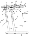
- Fig. 1 shows a table base frame according to the invention in a schematically simplified perspective view.
- One side of the table base frame is shown, which is provided with the reference number 2 and which serves to support a table top 4 against the floor.
- the table base frame 2 has the front or Narrow sides of the table top 4 each have a base frame 6 on that in the illustrated embodiment of two vertical extending support legs 8 and 10, and a bottom Support tube 12 is constructed, from which the Support legs 8 and 10 from up towards the table top 4 project.
- Fig. 1 Shown in Fig. 1 is the left side of the table base 2; the right side is analog and symmetrical to this built up.
- the table base frame 2 includes the two base frames 6 two more end rails, one of which in Fig. 1 again only the left support rail 14 is shown is. These support rails 14 run on the front or Narrow sides of the table top 4 and serve to accommodate or arrangement of the table top 4. Between the two support rails run in the embodiment shown in Fig. 1 two in the longitudinal direction of the table top 4 extending trusses 16 and 18 in the in the drawing embodiment shown have a round cross-section means that the trusses 16 and 18 are tubes.
- Each support leg 8 or 10 of the base frame 6 is in two parts executed: the support leg 8 consists of a fixed, on the support tube 12 fixed leg 20 and a frame leg 22 that is movably guided therein the support leg 10 consists of a stationary, on the support tube 12 fixed frame leg 24 and one movable therein guided leg 26.
- the support leg 8 consists of a fixed, on the support tube 12 fixed leg 20 and a frame leg 22 that is movably guided therein
- the support leg 10 consists of a stationary, on the support tube 12 fixed frame leg 24 and one movable therein guided leg 26.
- the fixed legs 20 and 24 round cross-section and those movably guided therein Legs 22 and 26 a polygon, preferred rectangular and in particular square cross section.
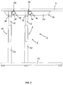
- Figures 2 to 4 show the attachment of the horizontal trusses 16 and 18, as well as the legs 22 and 26 on the carrier rail 14.
- each support rail 14 is a Angle profile with a horizontally lying leg 28, on which the table top 4 can be placed and one for this vertical vertical leg 30, which according to Fig. 1 lies on the outside of the table base frame 2.
- a receiving sleeve 32 and 34 At the bottom of the horizontal leg 28 is for each Leg 22 and 26 attached a receiving sleeve 32 and 34, especially bluntly attached and welded.
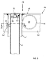
- One of the two receiving sleeves 32 and 34 for example the receiving sleeve 32 with reference to Figures 3 and 4 considered in more detail. The following, to the receiving sleeve 32nd statements made apply equally to the Receiving sleeve 34.
- the receiving sleeve 32 is in the immediate vicinity Neighborhood of the traverse 16 or is in with this Investment.
- the traverse 16 (and analogously to this the traverse 18) enforce receiving openings 36 (38) in the vertical Leg 30 of the support rail 14, that is, the cross member 16 (18) opens to the outside of the carrier rail 14.
- the Attaching the cross member 16 (18) in the receiving opening 36 (38) of the carrier rail 14 is carried out by one on the inside of the vertical leg 30 lying weld.
- the two trusses 16 and 18 thus form with the two end carrier rails 14 a first unit or assembly of the table base frame according to the invention.
- the two other units or assemblies are identified by the end Pedestals 6 formed.
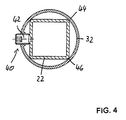
- the receiving sleeve 32 has a round cross section with a diameter such that the movable Rack leg 22 can be inserted therein with easy play.
- a clamping device 40 is provided for fastening the frame leg 22 in relation to the receiving sleeve 32.
- This Clamping device 40 is in accordance with a preferred embodiment from a clamping screw 42, in particular one Grub screw, which is screwed into an internal thread is that in a reinforced wall portion of the receiving sleeve 32 is formed.
- the free end of the clamping screw 42 bears against the outer wall of the frame leg 22 with recesses or depressions formed therein Intervention.
- a holding plate 48 is used and attached, for example, by welding.
- the holding plate 48 has an internal thread in a bore 50 on, from above a fastening screw 52 can be screwed in, which is the horizontal Leg 28 passes through the support rail 14.
- the frame leg is thus attached 22 on the support rail 14 in the immediate vicinity the horizontal traverse 16.
- the frame leg 26 is attached to the Carrier rail 14 in the immediate vicinity of the horizontal extending traverse 18.
- There are thus two three-dimensional Fastening nodes 54 and 56 formed where the Legs 22 and 26 in the Y direction, the support rail 14 in the X direction and the trusses 16 and 18 in the Z direction (see coordinates in Fig. 1) are summarized.
- the table base frame 2 has a very high stability, because on the one hand the trusses 16 and 18 from the inside, that means not visible, directly with the Carrier rails 14 are welded. Furthermore, the Receiving sleeves 32 and 34 also from the inside, that is not visible, welded to the support rails 14.
- the Fixing the legs 22 and 26 in the receiving sleeves 32 and 34 takes place via the clamping devices 40 with which the legs 22 and 26 along the two investment lines 44 and 46 against the inner peripheral wall or surface the receiving sleeves 32 and 34 are pressed.
- An additional Bracing takes place using the fastening screw 52, which is screwed into the holding plate 48 from above becomes.
- Table base 2 from three units or Assemblies, namely the two trusses 16 and 18 with on this end welded support rails 14 and two base frames 6. Placed flat on the floor points neither the assembly consisting of the trusses 16 and 18 with the support rails 14 still have the assemblies of the two Pedestals 6 elements, which are essential from the horizontal project. These three modules can thus be used in easily disassembled packed in a flat box, be stored and transported.
- Table base 2 are only the legs 22 and 26 inserted into the receiving sleeves 32 and 34, after which the clamping screws 42 are tightened and the fastening screws 52 are screwed in from above.
- the legs 22 and 26th compared to the fixed legs 20 and 25 with a known, adjustment mechanism not shown in the drawing moved and at the desired altitude the table top 4 still to be placed.
- the adjustment mechanism in the pedestals 6 in one certain grid dimension and is one between two grid dimensions lying height of the table top 4 desired, can after loosening or loosening the clamping screws 42 the Receiving sleeves 32 and 34 opposite the frame legs 22 and 26 moved or adjusted. It can also do this be expedient, a plurality of in the longitudinal direction of the frame legs 22 and 26 extending recesses or depressions to bring in the legs 22 and 26, in the then the free end of the clamping screw 42 can be inserted can.
- the cross members 16 and 18 pass through the carrier rail 14 in the vertical or vertical there Leg 30, for which purpose the receiving openings in this leg 30 36 and 38 are formed.
- Trusses 16 and 18 can here on the outside of the leg 30 with the outer surface flush or they can of this by a certain amount, for example 10 mm protrude. In any case, the trusses 16 and 18 from the inside on the leg 30 of the support rail 14 welded. The free openings of the trusses 16 and 18 can be closed with panels or plugs if so desired. After removing this Cladding or plugs can then enter the mouths or openings of the cross members 16 and 18 connecting or upgrading elements be inserted, which are then analogous to the Legs 22 and 26 polygons, preferably rectangular and in particular have a square cross section.
- Table base frame 2 in a horizontal or vertical Extend or upgrade level.
- Table base frame 2 can be another table base in alignment with the existing table base or at an angle to it such connectors are struck.
- the trusses 16 and 18 in the area the carrier rail 14 is also provided with a clamping device be, which analog to the clamping device 40 from a Clamping screw exists, with which then in the trusses 16th or 18 inserted connecting or upgrade elements are.
- the shape of the receiving sleeves and the legs and not on the shape shown limited.
- the receiving sleeves polygons, preferably rectangular and in particular square Cross section and the support legs round cross section to have.
- the round support leg is in the receiving sleeve prism-like braced. It is only essential that the legs and with a little play in the receptacles are insertable and then by means of the clamping device along defined contact lines opposite the receiving sleeves be determined.
- the shape of the trusses is not open that shown in the drawing and the description and explained tubular configuration limited. Angle-, Rectangular or U profiles etc. can be used equally.
- the support rails were used as angle rails described and illustrated; it goes without saying that the Cross-sections differing from this, for example a closed rectangular profile or a U-profile can have. As a result, a even tighter integration of the trusses and receiving sleeves in the support rails and thus an even higher stability be achieved.
- the receiving openings passing through the carrier rails for the trusses are for the reasons mentioned above (Chaining, upgrade) advantageous, but not mandatory necessary.
- the trusses can also be blunted from the inside the (closed) vertical leg of the respective carrier rail be placed and welded.
Landscapes
- Tables And Desks Characterized By Structural Shape (AREA)
- Polishing Bodies And Polishing Tools (AREA)
- Laminated Bodies (AREA)
- Devices For Use In Laboratory Experiments (AREA)
Abstract
Description
Claims (15)
- Tischuntergestell, insbesondere für einen Büro-, Labor- oder Arbeitstisch, mit wenigstens zwei zwischen den beiden Stirnseiten des Tischuntergestells (2) in Längsrichtung des Tisches verlaufenden Traversen (16, 18), wobei sich das Tischuntergestell (2) mit an den beiden Stirnseiten anordenbaren Fußgestellen (6) gegenüber dem Boden abstützt, wobei die Fußgestelle (6) horizontal verlaufende Trägerschienen (14) zur Unterstützung einer Tischplatte (4) aufweisen, welche im Bereich der Stirnseiten im wesentlichen senkrecht zu den Traversen (16, 18) und in einer Ebene verlaufen, welche zu der Ebene der Traversen (16, 18) parallel ist oder mit dieser zusammenfällt,
dadurch gekennzeichnet, daß
die stirnseitigen Trägerschienen (14) zur Unterstützung der Tischplatte (4) direkt mit den Traversen (16, 18) verbunden sind und unmittelbar benachbart zu den Verbindungsstellen mit den Traversen (16, 18) Aufnahmehülsen (32, 34) für Stützbeine (8, 10) der Fußgestelle (6) aufweisen, wobei die Aufnahmehülsen (32, 34) einen derartigen Querschnitt haben, daß obere Endbereiche (22, 26) jedes Stützbeins (8, 10) hierin mit Spiel einsteckbar und anschließend über eine Klemmvorrichtung (40) entlang zweier Anlagelinien (44, 46) an die innere Umfangsoberfläche der Aufnahmehülse (32, 34) unter Kraft anlegbar sind. - Tischuntergestell nach Anspruch 1, dadurch gekennzeichnet, daß die Traversen (16, 18) in Aufnahmeöffnungen (36, 38) in den Trägerschienen (14) eingestzt sind.
- Tischuntergestell nach Anspruch 1 oder 2, dadurch gekennzeichnet, daß die Aufnahmehülsen (32, 34) runden Querschnitt und die in die Aufnahmehülsen (32, 34) einsteckbaren oberen Endbereiche (22, 26) der Stützbeine (8, 10) polygonen, bevorzugt rechteckigen, insbesondere quadratischen Querschnitt haben.
- Tischuntergestell nach Anspruch 1 oder 2, dadurch gekennzeichnet, daß die Aufnahmehülsen (32, 34) polygonen, bevorzugt rechteckigen, insbesondere quadratischen Querschnitt und die in die Aufnahmehülsen (32, 34) einsteckbaren oberen Endbereiche (22, 26) der Stützbeine (8, 10) runden Querschnitt haben.
- Tischuntergestell nach einem der vorhergehenden Ansprüche, dadurch gekennzeichnet, daß die Klemmvorrichtung (40) pro Aufnahmehülse (32, 34) wenigstens eine, die Wand der Aufnahmehülse (32, 34) in einem dortigen Innengewinde durchsetzende Klemmschraube (42) aufweist, deren freies Ende an der Wand des oberen Endbereiches (22, 26) des jeweiligen Stützbeines (8, 10) unter Kraft anlegbar ist.
- Tischuntergestell nach Anspruch 5, dadurch gekennzeichnet, daß das freie Ende der Klemmschraube (42) in einer korrespondierenden Ausnehmung oder Bohrung in der Wand des oberen Endbereiches (22, 26) des jeweiligen Stützbeines (8, 10) aufnehmbar ist.
- Tischuntergestell nach Anspruch 6, dadurch gekennzeichnet, daß eine Mehrzahl von Ausnehmungen oder Bohrungen in Axialrichtung in der Wand des oberen Endbereiches (22, 26) des Stützbeines (8, 10) verlaufend vorgesehen ist.
- Tischuntergestell nach einem der Ansprüche 2 bis 7, dadurch gekennzeichnet, daß die Aufnahmeöffnungen (36, 38) im Querschnitt an den Querschnitt der Traversen (16, 18) angepaßt sind.
- Tischuntergestell nach Anspruch 8, dadurch gekennzeichnet, daß die Traversen (16, 18) die Trägerschienen (14) in den dortigen Aufnahmeöffnungen (36, 38) durchsetzen und zur Außenseite des Tischuntergestells (2) hin münden.
- Tischuntergestell nach Anspruch 9, dadurch gekennzeichnet, daß die Mündungen der Traversen (16, 18) durch Verblendungen oder Stopfen verschließbar sind.
- Tischuntergestell nach Anspruch 9 oder 10, dadurch gekennzeichnet, daß in die Mündungen der Traversen (16, 18) Anschluß- oder Aufrüstelemente einsteckbar und mittels weiterer Klemmvorrichtungen, insbesondere Klemmschrauben festlegbar sind.
- Tischuntergestell nach einem der vorhergehenden Ansprüche, dadurch gekennzeichnet, daß jede Trägerschiene (14) ein Winkelprofil mit zwei senkrecht zueinander stehenden Schenkeln (28, 30) ist.
- Tischuntergestell nach Anspruch 12, dadurch gekennzeichnet, daß ein Schenkel (28) horizontal verläuft, an seiner Oberseite zur Aufnahme der Tischplatte (4) und an seiner Unterseite zur Befestigung der Aufnahmehülsen (32, 34) dient und der andere Schenkel (30) senkrecht hierzu entlang der Tischuntergestell-Außenseite verläuft und die Aufnahmeöffnungen (36, 38) für die Traversen (16, 18) enthält.
- Tischuntergestell nach einem der vorhergehenden Ansprüche, dadurch gekennzeichnet, daß die Aufnahmehülsen (32, 34) an den Trägerschienen (14) an- und die Traversen (16, 18) in die Trägerschienen (14) bzw. die dortigen Aufnahmeöffnungen (36, 38) eingeschweißt sind.
- Tischuntergestell nach einem der vorhergehenden Ansprüche, dadurch gekennzeichnet, daß jedes Stützbein (8, 10) in seinem oberen Endbereich eine innenliegende Halteplatte (48) aufweist, welche eine Bohrung mit Innengewinde trägt, in welche von oben her eine den horizontalen Schenkel (28) der Trägerschiene (14) durchsetzende Befestigungsschraube (52) eindrehbar ist.
Applications Claiming Priority (2)
| Application Number | Priority Date | Filing Date | Title |
|---|---|---|---|
| DE29616744U DE29616744U1 (de) | 1996-09-25 | 1996-09-25 | Tischuntergestell |
| DE29616744U | 1996-09-25 |
Publications (2)
| Publication Number | Publication Date |
|---|---|
| EP0832581A2 true EP0832581A2 (de) | 1998-04-01 |
| EP0832581A3 EP0832581A3 (de) | 2000-05-10 |
Family
ID=8029744
Family Applications (1)
| Application Number | Title | Priority Date | Filing Date |
|---|---|---|---|
| EP97116580A Withdrawn EP0832581A3 (de) | 1996-09-25 | 1997-09-23 | Tischuntergestell |
Country Status (2)
| Country | Link |
|---|---|
| EP (1) | EP0832581A3 (de) |
| DE (1) | DE29616744U1 (de) |
Families Citing this family (1)
| Publication number | Priority date | Publication date | Assignee | Title |
|---|---|---|---|---|
| CN103230159B (zh) * | 2013-05-17 | 2015-12-02 | 河北联合大学 | 带有滚动装置的办公桌底架 |
Family Cites Families (9)
| Publication number | Priority date | Publication date | Assignee | Title |
|---|---|---|---|---|
| US2631076A (en) * | 1949-09-08 | 1953-03-10 | Redlich Mfg Company | Leg connector for table tops |
| US2671002A (en) * | 1950-03-04 | 1954-03-02 | John W Chaney | Table leg mounting arrangement |
| DE2414707A1 (de) * | 1974-03-27 | 1975-10-09 | Wessel Bueromoebel Willy | Schreibtisch |
| DE2949185C2 (de) * | 1979-12-06 | 1983-04-07 | Siemens AG, 1000 Berlin und 8000 München | Tischgestell für einen höhenverstellbaren Tisch |
| DE3625136C1 (en) * | 1986-07-25 | 1987-12-17 | Selecta Werk Gmbh Bank Und Kas | Work table, in particular office desk |
| DE3805592A1 (de) * | 1988-02-23 | 1989-08-31 | Gesika Bueromoebelwerk Gmbh | Verbindung fuer rahmenteile von moebeln, insbesondere bueromoebeln |
| DE3835365A1 (de) * | 1988-10-18 | 1990-04-19 | Gesika Bueromoebelwerk Gmbh | Vorrichtung zum verbinden einer schreibtischplatte mit einem traggestell |
| DE4021248A1 (de) * | 1990-07-04 | 1992-01-09 | Waiko Moebelwerke Gmbh & Co Kg | Bausatz zur herstellung von buero-arbeitstischen |
| FR2725763B1 (fr) * | 1994-10-17 | 1998-05-22 | Le Theo Catherine | Dispositif de solidarisation d'au moins un plateau plan et d'une ossature support, et utilisation pour l'assemblage de deux plateaux a surfaces superieures coplanaires |
-
1996
- 1996-09-25 DE DE29616744U patent/DE29616744U1/de not_active Expired - Lifetime
-
1997
- 1997-09-23 EP EP97116580A patent/EP0832581A3/de not_active Withdrawn
Also Published As
| Publication number | Publication date |
|---|---|
| DE29616744U1 (de) | 1996-11-14 |
| EP0832581A3 (de) | 2000-05-10 |
Similar Documents
| Publication | Publication Date | Title |
|---|---|---|
| DE3200310C2 (de) | Gestell aus mehreren Profilstäben | |
| EP4039131B1 (de) | Regalsystem | |
| DE3420648A1 (de) | Buerotisch, insbesondere fuer computer-peripheriegeraete | |
| DE2435147C3 (de) | Aus teilweise abgebogenen Profilstangen gebildetes Gestell | |
| DE4230949C1 (de) | Messe- und Ladenbauwand | |
| DE29601648U1 (de) | Regalaufbau zur Präsentation von Waren | |
| DE102008058903A1 (de) | Dreidimensionales Verbundsystem | |
| EP0832581A2 (de) | Tischuntergestell | |
| DE69824827T2 (de) | Trägerstruktur für einen modularen Schrank für elektrische oder elektronische Geräte | |
| DE3249214T1 (de) | Gestell, vorzugsweise moebelgestell | |
| DE29802617U1 (de) | Führungskette | |
| DE69319146T2 (de) | Zusammenstellbare regaleinheit | |
| DE60013058T2 (de) | Senkrechtes Lager | |
| DE2310583C3 (de) | Gestell für Möbel | |
| AT404895B (de) | Konstruktionssystem | |
| DE29722358U1 (de) | Modular aufgebautes Gestell | |
| DE3232091C1 (de) | Verbindung eines plattenfoermigen Moebelteils mit einer Traverse | |
| DE3725224A1 (de) | Regalstaender | |
| DE102008032433A1 (de) | Längsprofil, Einsteckhülse sowie Tragkonstruktion aus einem Längsprofil und einer Einsteckhülse | |
| DE8502705U1 (de) | Bueroschreibtisch mit c-foermigen seitenrahmen | |
| DE20302839U1 (de) | Möbelgerüst in Baukastenanordnung | |
| DE9407908U1 (de) | Bausystem zur Fertigung von Möbeln | |
| DE2430412A1 (de) | Mit laufrollen versehener transportbehaelter | |
| DE9303534U1 (de) | Regalsystem | |
| DE8508847U1 (de) | Hohlprofilleiste für Gestell- und Rahmenbau |
Legal Events
| Date | Code | Title | Description |
|---|---|---|---|
| PUAI | Public reference made under article 153(3) epc to a published international application that has entered the european phase |
Free format text: ORIGINAL CODE: 0009012 |
|
| AK | Designated contracting states |
Kind code of ref document: A2 Designated state(s): AT BE CH DE DK ES FI FR GB GR IE IT LI LU MC NL PT SE |
|
| PUAL | Search report despatched |
Free format text: ORIGINAL CODE: 0009013 |
|
| AK | Designated contracting states |
Kind code of ref document: A3 Designated state(s): AT BE CH DE DK ES FI FR GB GR IE IT LI LU MC NL PT SE |
|
| AKX | Designation fees paid | ||
| REG | Reference to a national code |
Ref country code: DE Ref legal event code: 8566 |
|
| STAA | Information on the status of an ep patent application or granted ep patent |
Free format text: STATUS: THE APPLICATION IS DEEMED TO BE WITHDRAWN |
|
| 18D | Application deemed to be withdrawn |
Effective date: 20001111 |