EP0832590A2 - Gargerät mit im Garraum abstellbarem Garbehältnis zum Dampfgaren - Google Patents
Gargerät mit im Garraum abstellbarem Garbehältnis zum Dampfgaren Download PDFInfo
- Publication number
- EP0832590A2 EP0832590A2 EP97114676A EP97114676A EP0832590A2 EP 0832590 A2 EP0832590 A2 EP 0832590A2 EP 97114676 A EP97114676 A EP 97114676A EP 97114676 A EP97114676 A EP 97114676A EP 0832590 A2 EP0832590 A2 EP 0832590A2
- Authority
- EP
- European Patent Office
- Prior art keywords
- cooking
- steam
- sensor
- cooking container
- control device
- Prior art date
- Legal status (The legal status is an assumption and is not a legal conclusion. Google has not performed a legal analysis and makes no representation as to the accuracy of the status listed.)
- Granted
Links
- 238000010411 cooking Methods 0.000 claims abstract description 110
- 238000000034 method Methods 0.000 claims description 11
- 238000010438 heat treatment Methods 0.000 claims description 10
- 238000001514 detection method Methods 0.000 description 4
- 238000010025 steaming Methods 0.000 description 2
- 238000009835 boiling Methods 0.000 description 1
- 230000001276 controlling effect Effects 0.000 description 1
- 238000010586 diagram Methods 0.000 description 1
- 230000000694 effects Effects 0.000 description 1
- 238000011156 evaluation Methods 0.000 description 1
- 239000008236 heating water Substances 0.000 description 1
- 238000009413 insulation Methods 0.000 description 1
- 238000005259 measurement Methods 0.000 description 1
- 238000012544 monitoring process Methods 0.000 description 1
- 238000012545 processing Methods 0.000 description 1
- 230000001105 regulatory effect Effects 0.000 description 1
- XLYOFNOQVPJJNP-UHFFFAOYSA-N water Substances O XLYOFNOQVPJJNP-UHFFFAOYSA-N 0.000 description 1
Images
Classifications
-
- A—HUMAN NECESSITIES
- A47—FURNITURE; DOMESTIC ARTICLES OR APPLIANCES; COFFEE MILLS; SPICE MILLS; SUCTION CLEANERS IN GENERAL
- A47J—KITCHEN EQUIPMENT; COFFEE MILLS; SPICE MILLS; APPARATUS FOR MAKING BEVERAGES
- A47J27/00—Cooking-vessels
- A47J27/04—Cooking-vessels for cooking food in steam; Devices for extracting fruit juice by means of steam ; Vacuum cooking vessels
-
- A—HUMAN NECESSITIES
- A47—FURNITURE; DOMESTIC ARTICLES OR APPLIANCES; COFFEE MILLS; SPICE MILLS; SUCTION CLEANERS IN GENERAL
- A47J—KITCHEN EQUIPMENT; COFFEE MILLS; SPICE MILLS; APPARATUS FOR MAKING BEVERAGES
- A47J36/00—Parts, details or accessories of cooking-vessels
- A47J36/32—Time-controlled igniting mechanisms or alarm devices
Definitions
- the present invention relates to a cooking device with a cooking space, in which one with a Cover that can be covered, pressure-free cooking container is adjustable, and with a steam generator, which feeds the cooking container via a steam line, and with a control device for controlling the steam generator and relates to a method for operating of a corresponding cooking device, first of all steam from a steam generator in a pressureless one covered with a lid, placed in the cooking space
- the cooking container is fed in, which steam is initially fed predominantly condensed food in the cooking container until the food to be cooked accordingly the temperature of the steam is warmed up and then the excess steam oozes from the cooking container.
- Such a cooking device and the method for operating the cooking device are known from European patent specification EP 0 165 187 B1. If this happens in the Cooking product located or the inner wall of the cooking container as a result the exposure to steam has reached a sufficient temperature, the steam fed into the cooking container hardly condenses on the food or on the inner wall. The large excess of steam becomes from the one press the lid of the covered cooking container into the cooking space. Disadvantageous is that the steam continues to be fed into the cooking container as long until the steam generator stops producing steam due to a lack of water. Thereby energy is unnecessarily wasted and the cooking space is unnecessarily moist.
- the object of the present invention is a cooking device and a corresponding cooking method to provide, which eliminate these disadvantages with simple means.
- this is achieved in a generic cooking appliance by that this is further developed according to the characterizing part of claim 1 and with a method according to the characterizing part of the claim 12 is operated.
- steaming the food is also heated Steam.
- the highest possible amount of steam is required to ensure that Heat the food as quickly as possible.
- the steam condenses on the food and gives thereby its heat energy from the food to be cooked (parboiling phase).
- the food has reached a temperature at which, if at all, only a small proportion of the steam condenses on the food to be cooked To replace energy losses in the cooking space or in the cooking container and the food to be cooked (Continued cooking phase).
- the senor is a temperature sensor. Because of the simple metrological task, namely essentially the A temperature sensor distinguishes between the "steam no" and “steam yes” states sufficient. This detects the jump in temperature caused by the Quilling of the hot steam is caused by the cooking container. A special one There is a large jump in temperature if the cooking space during the heating phase is not additionally heated with other heating elements usual in cooking appliances. If the cooking space can be heated with a heating element in other operating modes Temperature sensor advantageously in addition to regulating the heating element to serve.
- a moisture sensor is provided as a sensor. This reacts specifically to Changes in humidity and, if necessary, allows a more sensitive Detect the amount of steam or moisture in the cooking space.
- the moisture sensor is however more problematic in terms of its service life and reliability than for example a temperature sensor.
- the pressure sensor is an advantage arranged in the steam line through which the cooking container is fed with steam.
- a spatial storage area of the cooking container in the cooking space is advantageous fixed. This can be achieved in a simple manner by means of a rigid steam line, that protrudes from the wall of the oven into the interior of the oven. This ensures that the area in which the from the cooking container at the end of the parboiling phase escaping steam flows, is fixed.
- the sensor can be positioned accordingly so that the steam reaches the sensor without unnecessary delay can.
- the cooking container and / or the lid at least have a steam outlet opening that can be directed onto the sensor.
- the position of the steam outlet opening when it is inserted in the cooking space The cooking container is fixed relative to the sensor and cannot be changed by an operator will. This ensures that at the end of the parboiling phase it is almost always a burst of steam is aimed directly at the sensor.
- the cover is designed in such a way that that it is only due to a slight overpressure building up at the end of the parboiling phase Allows steam to escape from the cooking container.
- the detection of the end of the parboiling phase can be made more sensitive if the control device using the sensor an increase in the unit of time from the The amount of steam escaping from the cooking container is detected. During the parboiling phase this amount of steam is significantly less than zero under ideal conditions after the end of the parboiling phase. Likewise, if this is an advantage, an increase can occur the amount of steam emerging from the cooking container above a predetermined Threshold value can be detected. The effort involved is less than that Monitoring the amount of steam escaping per unit of time.
- the detection criterion for the end of the parboiling phase Criterion as the increase in the interior temperature of the cooking space or the sensor temperature be used.
- the inflow may cause the temperature sensor to flow be cooled with steam.
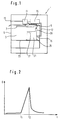
- An oven 1 has an oven muffle 3 which is in the front with a door 5 is lockable.
- the oven muffle 3 is in a manner known per se from thermal insulation surrounded (not shown) and with a top heat radiator 7 and optionally other radiators (not shown).
- Under the ceiling of the Oven muffle 3 is a temperature sensor 9 held in the oven muffle 3.
- the temperature sensor 9 is connected to a control device 11 via a control line of the oven 1 connected.
- the control device is in the area between the ceiling the oven muffle 3 and the ceiling of the cooking device 1 arranged.
- the front panel area of the cooking device 1 provided toggle 13 are below other via the control device 11 parameters for a steam generator 15, such as For example, the amount of steam and / or steam temperature to be generated can be specified.
- the outlet of the steam generator 15 is via a steam line 17 with an opening connected in a side wall of the oven muffle 3. With this opening is operationally a rigid tubular steam connector 19 can be coupled, which the Opening or the steam line 17 connects to a pot-shaped cooking container 21. This is placed on a support element 23 held in the oven muffle 3.
- the carrier element 23 can be arranged at different heights of the oven muffle 3. Therefore, it can also be provided if suitable measures are as follows are described, the steam connector 19 is not rigid, but flexible shape.
- the carrier element 23 for the geometric definition of the location that may be necessary of the cooking container 21 relative to the temperature sensor 9 has the carrier element 23 as A corresponding ring-shaped marking and fixing device on its upper side Survey 25 on.
- the cooking container 21 there is a food that is directly from the steam flowing from the steam connector 19 into the cooking container 21 (not shown) is flowed and heated.
- the cooking container 21 is at the top with a Closable cover 27, which has a steam outlet opening 29. This is on the Temperature sensor 9 directed.
- the position of the cooking container 21 or the steam outlet opening 29 relative to the temperature sensor 9 and the evaluation of its signal by the control device 11 are coordinated so that one end of the Parboiling phase is reliably recognized. One is possibly during the parboiling phase emerging from the steam outlet opening 29, slight amount of steam is taken into account.
- the function of the oven 1 and the corresponding cooking method is additionally indicated in FIG. 2.
- the cooking container 21 is positioned in the oven muffle in such a way that the steam outlet opening 29 is directed towards the temperature sensor 9.
- the position of the steam outlet opening 29 is fixed as described above.
- the cooking process is then started using the setting knob 13.
- the top heat radiator 7 remains switched off and the steam generator 15 begins to generate steam by heating water.
- only a small amount of steam D comes out of the steam outlet opening 29 from the cooking container 21, because the steam condenses predominantly on the food in the cooking container 21 or its inner wall.
- the boil-up phase ends at time t1.
- the food and the cooking container 21 are heated so far that the steam can no longer condense on them.
Landscapes
- Engineering & Computer Science (AREA)
- Food Science & Technology (AREA)
- Cookers (AREA)
Abstract
Description
- Fig. 1
- eine schematisierte Seitenansicht des erfindungsgemäßen Gargerätes zum Dampfgaren und
- Fig. 2
- ein Zeitdiagramm eines typischen Zeitverlaufes der Dampfmenge bei einem Garbetrieb entsprechend dem erfindungsgemäßen Garverfahren.
Claims (12)
- Gargerät mit einem Garraum, in den ein mit einem Deckel abdeckbares, druckloses Garbehältnis stellbar ist, und mit einem Dampferzeuger, der über eine Dampfleitung das Garbehältnis speist, und mit einer Steuervorrichtung zur Steuerung des Dampferzeugers, dadurch gekennzeichnet,
daß ein Sensor (9) mit der Steuervorrichtung (11) verbunden ist, der das Austreten des Dampfes aus dem Garbehältnis (21) detektiert, und daß die Steuervorrichtung (11) beim Empfang des entsprechenden Signals des Sensors (9) die in das Garbehältnis eingespeiste Dampfmenge reduziert. - Gargerät nach Anspruch 1, dadurch gekennzeichnet, daß der Sensor ein Temperatursensor (9) ist.
- Gargerät nach Anspruch 2, dessen Garraum mit zumindest einem Heizelement beheizbar ist, dadurch gekennzeichnet, daß der Temperatursensor (9) zur Regelung des Heizelementes (7) dient.
- Gargerät nach Anspruch 1, dadurch gekennzeichnet, daß der Sensor ein Feuchtesensor ist.
- Gargerät nach einem der vorhergehenden Ansprüche, dadurch gekennzeichnet, daß ein räumlicher Abstellbereich für das Garbehältnis (21) im Garraum (3) festgelegt ist.
- Gargerät nach einem der vorhergehenden Ansprüche, dadurch gekennzeichnet, daß das Garbehältnis und/oder der Deckel (27) zumindest eine auf den Sensor (9) gerichtete Dampfaustrittsöffnung (29) aufweisen.
- Gargerät nach Anspruch 6, dadurch gekennzeichnet, daß die Lage der Dampfaustrittsöffnung (29) bei in den Garraum (3) eingesetztem Garbehältnis (21) relativ zum Sensor (9) festlegbar ist.
- Gargerät nach einem der vorhergehenden Ansprüche, dadurch gekennzeichnet, daß die Steuervorrichtung (11) mithilfe des Sensors (9) ein Ansteigen der je Zeiteinheit aus dem Garbehältnis austretenden Dampfmenge detektiert.
- Gargerät nach einem der vorhergehenden Ansprüche, dadurch gekennzeichnet, daß die Steuervorrichtung (11) mithilfe des Sensors (9) ein Ansteigen der aus dem Garbehältnis austretenden Dampfmenge über einen Schwellwert detektiert.
- Gargerät nach einem der vorhergehenden Ansprüche, dadurch gekennzeichnet, daß die Steuervorrichtung (11) mithilfe des Sensors (9) ein Ansteigen der je Zeiteinheit auftretenden Änderung der Garraum-Innentemperatur detektiert.
- Gargerät nach einem der vorhergehenden Ansprüche, dadurch gekennzeichnet, daß die Steuervorrichtung (11) mithilfe des Sensors (9) ein Ansteigen der Garraum-Innentemperatur über einen Grenzwert detektiert.
- Verfahren zum Betreiben eines Gargerätes mit einem Garraum, wobei zunächst Dampf von einem Dampferzeuger in ein mit einem Deckel abgedecktes, druckloses im Garraum abgestelltes Garbehältnis eingespeist wird, welcher eingespeiste Dampf zunächst überwiegend an einem im Garbehältnis befindlichen Gargut kondensiert, bis das Gargut entsprechend der Temperatur des Dampfes erwärmt ist und der Dampf anschließend aus dem Garbehältnis quillt, dadurch gekennzeichnet, daß das Überquillen von einem Sensor (9) detektiert wird, und eine Steuervorrichtung (11) beim Empfang des entspechenden Signals des Sensors die in das Garbehältnis (21) eingespeiste Dampfmenge reduziert.
Applications Claiming Priority (2)
| Application Number | Priority Date | Filing Date | Title |
|---|---|---|---|
| DE19638664A DE19638664A1 (de) | 1996-09-20 | 1996-09-20 | Gargerät mit im Garraum abstellbarem Garbehältnis zum Dampfgaren |
| DE19638664 | 1996-09-20 |
Publications (3)
| Publication Number | Publication Date |
|---|---|
| EP0832590A2 true EP0832590A2 (de) | 1998-04-01 |
| EP0832590A3 EP0832590A3 (de) | 1998-04-22 |
| EP0832590B1 EP0832590B1 (de) | 2003-11-05 |
Family
ID=7806398
Family Applications (1)
| Application Number | Title | Priority Date | Filing Date |
|---|---|---|---|
| EP97114676A Expired - Lifetime EP0832590B1 (de) | 1996-09-20 | 1997-08-25 | Gargerät mit im Garraum abstellbarem Garbehältnis zum Dampfgaren |
Country Status (2)
| Country | Link |
|---|---|
| EP (1) | EP0832590B1 (de) |
| DE (2) | DE19638664A1 (de) |
Cited By (4)
| Publication number | Priority date | Publication date | Assignee | Title |
|---|---|---|---|---|
| FR2823962A1 (fr) * | 2001-04-26 | 2002-10-31 | Seb Sa | Appareil electromenager de cuisson a la vapeur a degagement de vapeur reduit |
| CN102920315A (zh) * | 2012-10-21 | 2013-02-13 | 安徽工程大学 | 一种可控温湿度的智能蒸菜方法 |
| CN108937603A (zh) * | 2018-09-29 | 2018-12-07 | 杭州老板电器股份有限公司 | 蒸汽量检测装置 |
| CN112971516A (zh) * | 2019-12-16 | 2021-06-18 | E.G.O.电气设备制造股份有限公司 | 操作蒸汽发生器的方法、蒸汽发生器和具有蒸汽发生器的烹饪装置 |
Families Citing this family (8)
| Publication number | Priority date | Publication date | Assignee | Title |
|---|---|---|---|---|
| DE10305440B4 (de) * | 2002-06-14 | 2012-11-15 | Electrolux Professional Gmbh | Gareinheit |
| DE10335295B4 (de) * | 2003-07-28 | 2008-02-21 | Igv Institut Für Getreideverarbeitung Gmbh | Verfahren und Vorrichtung zur Steuerung von Backparametern |
| EP1772080A3 (de) * | 2005-09-26 | 2009-03-04 | Miele & Cie. KG | Verfahren und Vorrichtung zum Garen mit Dampf |
| JP5517736B2 (ja) * | 2010-05-14 | 2014-06-11 | 日立アプライアンス株式会社 | 加熱調理器 |
| DE102010063716A1 (de) * | 2010-12-21 | 2012-06-21 | BSH Bosch und Siemens Hausgeräte GmbH | Dampfbehandlungseinsatz, Gargerät und System mit Gargerät und Dampfbehandlungseinsatz |
| DE102011051530B4 (de) * | 2011-07-04 | 2017-06-08 | Miele & Cie. Kg | Gargerät |
| DE102018101068A1 (de) * | 2018-01-18 | 2019-07-18 | Klaus Lösche | Gärapparat zum Gären von Teiglingen sowie Verfahren, insbesondere zum Betreiben eines solchen Gärapparates |
| CN112773181B (zh) * | 2019-11-11 | 2025-08-26 | 厦门翔澧工业设计有限公司 | 一种蒸汽热流循环蒸煮器 |
Family Cites Families (7)
| Publication number | Priority date | Publication date | Assignee | Title |
|---|---|---|---|---|
| JPS58194747U (ja) * | 1982-06-18 | 1983-12-24 | 大畠 隆 | 加工食品保管庫 |
| FR2564308B1 (fr) * | 1984-05-17 | 1987-08-21 | Jovanovic Dragomir | Appareil de cuisson a injection de vapeur a pression atmospherique |
| DE3579871D1 (de) * | 1984-08-04 | 1990-10-31 | Lechmetall Landsberg Gmbh | Vorrichtung zur waermebehandlung von nahrungsmitteln bzw. speisen mit messfuehlerrohr. |
| GB2198631A (en) * | 1986-12-15 | 1988-06-22 | Kenwood Ltd | A device for heating liquid |
| DE4116425A1 (de) * | 1990-06-26 | 1992-01-02 | Esser Hans Peter | Vorrichtung zum erhitzen von nahrungsmitteln |
| EP0517681A2 (de) * | 1991-06-07 | 1992-12-09 | SMEG S.p.A. | Dampfkochherd |
| DE4401642A1 (de) * | 1994-01-21 | 1995-07-27 | Gaggenau Werke | Vorrichtung zum Dampfgaren |
-
1996
- 1996-09-20 DE DE19638664A patent/DE19638664A1/de not_active Withdrawn
-
1997
- 1997-08-25 DE DE59710952T patent/DE59710952D1/de not_active Expired - Lifetime
- 1997-08-25 EP EP97114676A patent/EP0832590B1/de not_active Expired - Lifetime
Cited By (8)
| Publication number | Priority date | Publication date | Assignee | Title |
|---|---|---|---|---|
| FR2823962A1 (fr) * | 2001-04-26 | 2002-10-31 | Seb Sa | Appareil electromenager de cuisson a la vapeur a degagement de vapeur reduit |
| US6474222B1 (en) | 2001-04-26 | 2002-11-05 | Seb S.A. | Domestic electrical appliance for steam cooking with reduced release of steam |
| EP1260164A1 (de) * | 2001-04-26 | 2002-11-27 | Seb S.A. | Küchengerät zum Dampfkochen mit limitierter Dampfausgabe |
| CN102920315A (zh) * | 2012-10-21 | 2013-02-13 | 安徽工程大学 | 一种可控温湿度的智能蒸菜方法 |
| CN108937603A (zh) * | 2018-09-29 | 2018-12-07 | 杭州老板电器股份有限公司 | 蒸汽量检测装置 |
| CN112971516A (zh) * | 2019-12-16 | 2021-06-18 | E.G.O.电气设备制造股份有限公司 | 操作蒸汽发生器的方法、蒸汽发生器和具有蒸汽发生器的烹饪装置 |
| CN112971516B (zh) * | 2019-12-16 | 2023-12-12 | E.G.O.电气设备制造股份有限公司 | 操作蒸汽发生器的方法、蒸汽发生器和具有蒸汽发生器的烹饪装置 |
| US11980314B2 (en) | 2019-12-16 | 2024-05-14 | E.G.O. Elektro-Geraetebau Gmbh | Method of operating a steam generator, steam generator and cooking device with a steam generator |
Also Published As
| Publication number | Publication date |
|---|---|
| EP0832590A3 (de) | 1998-04-22 |
| EP0832590B1 (de) | 2003-11-05 |
| DE59710952D1 (de) | 2003-12-11 |
| DE19638664A1 (de) | 1998-03-26 |
Similar Documents
| Publication | Publication Date | Title |
|---|---|---|
| DE69832329T2 (de) | Verfahren und Vorrichtung zur Regelung eines elektrischen Heizelementes | |
| EP0832590B1 (de) | Gargerät mit im Garraum abstellbarem Garbehältnis zum Dampfgaren | |
| DE4136133A1 (de) | Anordnung zur regelung der heizleistung fuer einen kochtopf | |
| EP1212570B1 (de) | Kochherd | |
| EP2472999B1 (de) | Kochfeld und Verfahren zur Steuerung einer Energiezufuhr an ein Heizelement eines Kochfeldes | |
| EP1391141B1 (de) | Verfahren und vorrichtung zur begrenzung und/oder steuerung der oberflächentemperatur eines kochfelds | |
| EP2220432A2 (de) | Dampferzeuger, garvorrichtung, verfahren zum betrieb beziehungsweise zur herstellung eines dampferzeugers sowie verfahren zum kühlen einer heizvorrichtung | |
| EP3267113A1 (de) | Verfahren zum betrieb eines kochfelds und kochfeld | |
| DE3415849A1 (de) | Backofen mit pyrolytischem reinigungssystem | |
| DE2627373B2 (de) | Signaleinrichtung an Kochgeräten mit einer Glaskeramikkochfläche | |
| DE3821205A1 (de) | Kombiniertes daempf- und heissumluftgeraet | |
| EP0513721B1 (de) | Verfahren und Vorrichtung zur Steuerung eines Back-/Bratvorgangs | |
| DE3413650C2 (de) | ||
| EP2662631A1 (de) | Verfahren zum Garen eines Gargutes und Gargerät | |
| DE10240175A1 (de) | Verfahren zum Betrieb eines Gargeräts | |
| EP2445311B1 (de) | Kombigargerät | |
| EP1492385B1 (de) | Verfahren und Vorrichtung zur Erkennung von Erwärmungsvorgängen | |
| DE4104677A1 (de) | Verfahren zur automatischen leistungsanpassung | |
| DE2721921C3 (de) | Gas-Kocheinrichtung mit einer gasdichten Abdeckplatte | |
| DE19907049B4 (de) | Dampfgargerät mit Dampfmengenregelung | |
| DE4333585C2 (de) | Herd mit einem als Backrohr nutzbaren, elektrisch oder mittels Gas beheizbaren Backraum | |
| EP2712526A1 (de) | Garsystem | |
| CH697855B1 (de) | Gargerät mit induktiver Heizung. | |
| EP1342441B1 (de) | Druckgargerät | |
| DE69112403T2 (de) | Kochofen. |
Legal Events
| Date | Code | Title | Description |
|---|---|---|---|
| PUAI | Public reference made under article 153(3) epc to a published international application that has entered the european phase |
Free format text: ORIGINAL CODE: 0009012 |
|
| PUAL | Search report despatched |
Free format text: ORIGINAL CODE: 0009013 |
|
| AK | Designated contracting states |
Kind code of ref document: A2 Designated state(s): DE FR GB IT SE |
|
| AK | Designated contracting states |
Kind code of ref document: A3 Designated state(s): AT BE CH DE DK ES FI FR GB GR IE IT LI LU MC NL PT SE |
|
| RAP1 | Party data changed (applicant data changed or rights of an application transferred) |
Owner name: BSH BOSCH UND SIEMENS HAUSGERAETE GMBH |
|
| 17P | Request for examination filed |
Effective date: 19981012 |
|
| AKX | Designation fees paid |
Free format text: DE FR GB IT SE |
|
| RBV | Designated contracting states (corrected) |
Designated state(s): DE FR GB IT SE |
|
| 17Q | First examination report despatched |
Effective date: 20001016 |
|
| GRAH | Despatch of communication of intention to grant a patent |
Free format text: ORIGINAL CODE: EPIDOS IGRA |
|
| GRAS | Grant fee paid |
Free format text: ORIGINAL CODE: EPIDOSNIGR3 |
|
| GRAA | (expected) grant |
Free format text: ORIGINAL CODE: 0009210 |
|
| AK | Designated contracting states |
Kind code of ref document: B1 Designated state(s): DE FR GB IT SE |
|
| PG25 | Lapsed in a contracting state [announced via postgrant information from national office to epo] |
Ref country code: IT Free format text: LAPSE BECAUSE OF FAILURE TO SUBMIT A TRANSLATION OF THE DESCRIPTION OR TO PAY THE FEE WITHIN THE PRESCRIBED TIME-LIMIT;WARNING: LAPSES OF ITALIAN PATENTS WITH EFFECTIVE DATE BEFORE 2007 MAY HAVE OCCURRED AT ANY TIME BEFORE 2007. THE CORRECT EFFECTIVE DATE MAY BE DIFFERENT FROM THE ONE RECORDED. Effective date: 20031105 Ref country code: GB Free format text: LAPSE BECAUSE OF FAILURE TO SUBMIT A TRANSLATION OF THE DESCRIPTION OR TO PAY THE FEE WITHIN THE PRESCRIBED TIME-LIMIT Effective date: 20031105 Ref country code: FR Free format text: LAPSE BECAUSE OF FAILURE TO SUBMIT A TRANSLATION OF THE DESCRIPTION OR TO PAY THE FEE WITHIN THE PRESCRIBED TIME-LIMIT Effective date: 20031105 |
|
| REG | Reference to a national code |
Ref country code: GB Ref legal event code: FG4D Free format text: NOT ENGLISH |
|
| REF | Corresponds to: |
Ref document number: 59710952 Country of ref document: DE Date of ref document: 20031211 Kind code of ref document: P |
|
| RAP2 | Party data changed (patent owner data changed or rights of a patent transferred) |
Owner name: BSH BOSCH UND SIEMENS HAUSGERAETE GMBH |
|
| PG25 | Lapsed in a contracting state [announced via postgrant information from national office to epo] |
Ref country code: SE Free format text: LAPSE BECAUSE OF FAILURE TO SUBMIT A TRANSLATION OF THE DESCRIPTION OR TO PAY THE FEE WITHIN THE PRESCRIBED TIME-LIMIT Effective date: 20040205 |
|
| GBV | Gb: ep patent (uk) treated as always having been void in accordance with gb section 77(7)/1977 [no translation filed] |
Effective date: 20031105 |
|
| PLBE | No opposition filed within time limit |
Free format text: ORIGINAL CODE: 0009261 |
|
| STAA | Information on the status of an ep patent application or granted ep patent |
Free format text: STATUS: NO OPPOSITION FILED WITHIN TIME LIMIT |
|
| 26N | No opposition filed |
Effective date: 20040806 |
|
| EN | Fr: translation not filed | ||
| PGFP | Annual fee paid to national office [announced via postgrant information from national office to epo] |
Ref country code: DE Payment date: 20160831 Year of fee payment: 20 |
|
| REG | Reference to a national code |
Ref country code: DE Ref legal event code: R071 Ref document number: 59710952 Country of ref document: DE |