EP0832833B1 - Appareil d'alimentation de feuilles - Google Patents
Appareil d'alimentation de feuilles Download PDFInfo
- Publication number
- EP0832833B1 EP0832833B1 EP97116874A EP97116874A EP0832833B1 EP 0832833 B1 EP0832833 B1 EP 0832833B1 EP 97116874 A EP97116874 A EP 97116874A EP 97116874 A EP97116874 A EP 97116874A EP 0832833 B1 EP0832833 B1 EP 0832833B1
- Authority
- EP
- European Patent Office
- Prior art keywords
- gear
- sheet
- notched
- sheet supply
- drive
- Prior art date
- Legal status (The legal status is an assumption and is not a legal conclusion. Google has not performed a legal analysis and makes no representation as to the accuracy of the status listed.)
- Expired - Lifetime
Links
- 230000001276 controlling effect Effects 0.000 claims description 29
- 230000001105 regulatory effect Effects 0.000 claims description 21
- 238000000926 separation method Methods 0.000 claims description 12
- 230000005540 biological transmission Effects 0.000 claims description 4
- 230000003247 decreasing effect Effects 0.000 claims 2
- 238000006073 displacement reaction Methods 0.000 claims 1
- 238000010276 construction Methods 0.000 description 3
- 230000015572 biosynthetic process Effects 0.000 description 2
- 230000003287 optical effect Effects 0.000 description 2
- 230000001360 synchronised effect Effects 0.000 description 2
- 230000006835 compression Effects 0.000 description 1
- 238000007906 compression Methods 0.000 description 1
- 238000007599 discharging Methods 0.000 description 1
- 230000000977 initiatory effect Effects 0.000 description 1
- 238000009434 installation Methods 0.000 description 1
- 230000000087 stabilizing effect Effects 0.000 description 1
- 238000011144 upstream manufacturing Methods 0.000 description 1
Images









Classifications
-
- B—PERFORMING OPERATIONS; TRANSPORTING
- B65—CONVEYING; PACKING; STORING; HANDLING THIN OR FILAMENTARY MATERIAL
- B65H—HANDLING THIN OR FILAMENTARY MATERIAL, e.g. SHEETS, WEBS, CABLES
- B65H3/00—Separating articles from piles
- B65H3/02—Separating articles from piles using friction forces between articles and separator
- B65H3/06—Rollers or like rotary separators
- B65H3/0669—Driving devices therefor
Definitions
- the present invention relates to a drive controlling apparatus, and more particularly, it relates to a drive controlling apparatus used in a sheet supplying apparatus provided in an image forming apparatus.
- Conventional image forming apparatuses such as copying machines, printers and the like each has a sheet supplying apparatus in which a drive controlling apparatus for controlling the driving of a sheet supply roller is used.
- Such a drive controlling apparatus includes a sheet cassette portion, a drive portion, a sheet supply roller portion and a lock portion. Now, these portions will be briefly described.
- the sheet cassette portion comprises a sheet cassette 108 and sheets 100, and the sheet cassette is provided with an intermediate plate 108b pivotable around a fulcrum 108a, and projections 108c are provided on a downstream (in a sheet supplying direction) end portion of the intermediate plate.
- Springs 108d disposed below the intermediate plate serve to bias the intermediate plate 108b in a direction shown by the arrow X.
- the entire sheet supply portion 121 is rotated in the direction Y by a predetermined angle, with the result that a toothed portion of the notched gear 121d is engaged by a drive gear 127 rotated by a motor M in a direction W. Consequently, the sheet supply portion 121 is rotated by one revolution until a condition shown in Fig. 18 is restored again. After one revolution, when a non-toothed portion 121e of the notched gear 121b is opposed to the drive gear 127 again, the locking pawl 121d is locked by the stopper 122 again.
- the engagement and disengagement between the locking member 121c (locking pawl 121d) and the stopper 122 is effected by a spring 122c for biasing the stopper 122 in a direction Z and a lock releasing portion for urging the stopper 122 in opposition to the force of the spring 122c.
- a locking member 123c of the lock releasing portion is rotated to urge the stopper 122 in opposition to the force of the spring thereby to disengage the stopper 122 from the locking pawl 121d of the sheet supply roller portion, thus starting the rotation of the sheet supply roller portion.
- the stopper 122 is always urged against the locking member 121c of the sheet supply roller portion by means of the spring 122c.
- the lock releasing portion includes a cam 123a, a notched gear 123b, a locking member 123c (which are mounted on a common rotary shaft), a leaf spring 125 for applying a rotational force to the cam 123a, and a solenoid 126 for controlling the timing of rotation.
- a cam 123a tries to rotate in a direction V by the action of the leaf spring 125, since a locking pawl 123d of the locking member 123c is locked by a solenoid actuator 126a, the entire lock releasing portion is held stationary.
- a biasing force of such a spring acts as a rotational force for rotating a sheet supply roller via a cam, and, when a notched gear is engaged by a drive gear after the lock is released, the excessive force also acts on the drive gear.
- the increase in the rotational speed of the drive gear affects an influence upon all of gears associated with the drive gear. For example, as is in a normal case, when the drive gear is associated with a convey roller gear for directly conveying a sheet to a transfer portion, a rotational speed of the convey roller is also increased to push the sheet into the transfer portion excessively, thereby causing deviation of an image and worsening image quality. Further, the convey speed of the entire convey portion is unbalanced, thereby causing sheet jam.
- a preferred use of the apparatus is defined in claim 19.
- Figs. 1A, 1B, 2A and 2B schematically show a sheet supplying apparatus using a drive controlling apparatus according to a preferred embodiment of the present invention.
- Figs. 3A to 3D show an operation of the sheet supplying apparatus.
- the sheet supplying apparatus comprises a semi-circular sheet supply roller 1 secured to a rotary shaft 12, and rollers 3 rotatably mounted on the rotary shaft 12 on both sides of the sheet supply roller 1.
- An intermediate plate 16 is supported for pivotal movement around an upstream (in a supplying direction of a sheet 2 shown by the arrow in Fig. 1A) end thereof and is biased toward the sheet supply roller 1 by means of coil springs 16b.
- Cams 17 are secured to the rotary shaft 12 and projections 16a are secured to the intermediate plate 16 so that the cams are contacted with the projections.
- the cams 17 urges the projections 16a downwardly, thereby separating the sheet supply roller 1 and the rollers 3 from the sheet stack 2 rested on the intermediate plate 16 in a condition that a cut-out portion or flat portion of the sheet supply roller 1 is opposed to the sheet stack 2. In this way, the operability for removing the sheets from the intermediate plate 16 and for replenishing the sheet onto the intermediate plate can be improved.
- a separation pad 8 is biased toward the sheet supply roller 1 by a coil spring 8a to separate the sheets (on the intermediate plate 16) fed to the sheet supply roller 1 one by one.
- the sheet separated by the separation pad 8 is conveyed toward an image forming means by means of a pair of convey rollers 24.
- the intermediate plate 16 in the sheet supply, if the intermediate plate 16 is in the elevated position, the sheet to be supplied is pinched not only between the separation pad 8 and the rollers 3 but also between the sheet stack 2 rested on the intermediate plate 16 and the rollers 3, with the result that a load acting on the sheet becomes great, thereby increasing the load of a drive system. To avoid this, when the sheet reaches the downstream convey rollers, the intermediate plate 16 is lowered by the cams 17 to decrease the load acting on the sheet.
- the rollers 3 disposed on both sides of the sheet supply roller 1 have diameters slightly smaller than a diameter of a cylindrical portion of the sheet supply roller 1 so that, when the flat portion of the sheet supply roller 1 is opposed to the separation pad 8, the rollers 3 urge the sheet against the separation pad 8, thereby stabilizing the separation of the sheet on the separation pad 8.
- the rollers can be rotated in a reverse direction, if the sheet is jammed between the sheet supply roller 1 and the separation pad 8, the jammed sheet can easily be removed, thereby facilitating the jam treatment.
- each cam 17 is provided with a recess 17a.
- the recesses 17a of the cams 17 are engaged by the projections 16a of the intermediate plate 16, the rotary shaft 12 and the sheet supply roller 1 are held stationary.
- a drive controlling apparatus for controlling the transmission of a driving force to the sheet supply roller 1 is provided on one end of the rotary shaft 12.
- the drive controlling apparatus includes a drive gear 4 connected to a drive source such as a motor (not shown), and first and second notched gears 14, 6 which can be engaged by the drive gear 4.
- the first notched gear 14 is attached to the rotary shaft 12 so that, when the recesses 17a of the cams 17 are engaged by the projections 16a of the intermediate plate 16, a non-toothed portion of the first notched gear is opposed to the drive gear 4.
- the recesses 17a and the projections 16a act as a first regulating means for regulating the first notched gear 14.
- recesses may be provided in the projections of the intermediate plate 16 and projections may be provided on the cams 17.
- the second notched gear 6 has a key-way 5 loosely fitted on a key portion 12a of the rotary shaft 12 so that the second notched gear can be rotated within a predetermined range. Further, the second notched gear 6 is provided with a pawl portion 13 which extends through a slot 14a formed in the first notched gear 14 and is engaged or locked by a solenoid 7 disposed at an opposite side (near the sheet supply roller 1) of the first notched gear 14 with respect to the second notched gear 6. In this case, the second notched gear 6 and the solenoid 7 are so arranged that the second notched gear 6 is held stationary by the solenoid in a condition that a non-toothed portion of the second notched gear 6 is opposed to the drive gear 4. Thus, the pawl portion 13 and the solenoid 7 act as a second regulating means for regulating the second notched gear 6.
- the solenoid 7 is disposed nearer to the sheet supply roller 1 than the first notched gear 14 is that the entire apparatus is prevented from becoming bulky in a width-wise direction of the sheet due to the installation space of the solenoid 7. Thus, so long as the entire apparatus does not become bulky, the solenoid can be disposed at any position.
- a spring 10 serves as a rotating means and has one end secured to a fixed portion 11 of the first notched gear 14 and the other end secured to a fixed portion 9 of the second notched gear 6. An elastic force is generated in the spring in dependence upon a relative position between the first and second notched gears 14 and 6. Since the first notched gear 14 and the sheet supply roller 1 are secured to the rotary shaft 12, the sheet supply roller 1 is rotated together with the first notched gear 14.
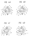
- Fig. 3A shows an initial condition. In this condition, the non-toothed portion of the first notched gear 14 is aligned with the non-toothed portion of the second notched gear 6 in the axial direction, and these gears 14, 6 are not engaged by the drive gear 4.
- the spring (biasing means) 10 generates a given elastic force in the compression direction, but the first and second notched gears 14, 6 are held stationary in opposition to the elastic force.
- the reason why the first notched gear 14 is held stationary is that, as shown in Fig. 1A, the first notched gears 14 is fixed to the cams 17 via the rotary shaft 12 and the recesses 17a (first regulating means) of the cams 17 are engaged by the projections 16a of the intermediate plate 16 to provide the stable condition, as shown in Fig. 2A.
- the reason why the second notched gear 6 is held stationary is that the locking pawl (locking portion) 13 of the second notched gear is locked (engaged) by a locking pawl 7a of the solenoid (second regulating means) 7 which is now disenergized.
- a side wall 5a of the key-way 5 abuts against the key portion 12a to rotate the first notched gear 14 (together with the second notched gear 6) until the first notched gear is engaged by the drive gear 4.
- the side wall 5a of the key-way 5 is so configured that, when the side wall 5a abuts against the key portion 12a, angular phases of teeth of the first and second notched gears 14, 6 are aligned with each other, with the result that, when the first notched gear 14 is engaged by the drive gear 4, there is no interference between the teeth of the gears 14 and 4.
- the biasing force of the springs 16b acting on the intermediate plate 16 may act on the cams 17 via the projections 16a as a rotational force for rotating the first notched gear 14.
- this rotational force causes the rotary shaft 12 to rotate faster than the second notched gear 6. Even when the key portion 12a is separated from the side wall 5a of the key-way 5, since there is the clearance, the rotational speed of the second notched gear 6 is not increased. Further, since the rotational force is ceased before the first notched gear 14 is engaged by the drive gear 4, the key portion 12a abuts against the side wall 5a of the key-way 5 again, thereby continuing the rotation.
- the biasing force from the intermediate plate 16 acts on the cams 17 as the rotational force only while the rotary shaft is rotated through an angle of about e shown in Fig. 2A.
- an angle through which the rotary shaft must be rotated to engage the first notched gear 14 with the drive gear 4 is selected to be greater than the angle ⁇ , the rotational force is not transmitted to the drive gear 4 through the first notched gear 14.
- the first notched gear 14 and accordingly the sheet supply roller 1 can start to rotate without affecting any force to the drive gear 4 and without arising any problem due to the backlash.
- first notched gear 14 After the first notched gear 14 is smoothly engaged by the drive gear 4 in this way, the first notched gear 14 continues to be rotated by the drive gear 4.
- condition shown in Fig. 3C in which the sheet supply roller 1 starts to pick up and convey the sheet i.e., condition shown in Fig. 3C in which the sheet supply roller 1 starts to pick up and convey the sheet
- the gears when the gears are further rotated, after the second notched gear 6 is rotated by one revolution, it is disengaged from the drive gear 4 (condition shown in Fig. 3D).
- the force of the projections 16a acting on the recesses 17a immediately before the recesses 17a are engaged by the projections 16a is set so at to act as the rotational force for rotating the cams 17 in the direction for engaging the recesses 17a with the projections 16a.
- the sheet supply roller 1 can be driven smoothly and efficiently with a simple construction and the jam treatment and the replenishment of sheets can be performed easily.
- a cooperating means is constituted by key portions 14a provided on a first notched gear 14 and key-ways 6a formed in a second notched gear 6, and, the key portions 14a and key-ways 6a are not positioned on the rotary shaft 12 but are spaced apart from the rotary shaft.
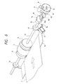
- a first notched gear 14 has a toothed portion 15 provided thereon only at a rear portion thereof in a rotational direction, as shown in Fig. 6.
- a second notched gear 6 has a toothed portion provided thereon only at a front portion thereof in a rotational direction, as shown in Fig. 7. That is to say, while the second notched gear 6 receiving the rotation starting force from the spring 10 is being rotated while engaging with the drive gear 4, the side wall 5a of the key-way 5 abuts against the key portion 12a of the rotary shaft 12 to start the rotation of the first notched gear 14. The second notched gear 6 plays an role for rotating the first notched gear 14 until the first notched gear is engaged by the drive gear 4.
- spring 10 is used as the rotating means and the key-way 5 and the key portion 12a are used as the cooperating means.
- spring constant of the spring 10 and dimension of the non-toothed portion of the first notched gear 14 are selected so that the first notched gear 14 is engaged by the drive gear 4 after the rotational force transmitted from the cams 17 is absorbed by the spring 10.
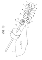
- a one-way clutch 19 is provided between the first notched gear 14 and the rotary shaft 12 so that the sheet supply roller alone can be rotated in the sheet supplying direction (even when the first notched gear is stopped).
- a half clutch portion of the one-way clutch 19 is integrally formed with the first notched gear 14 and the other half clutch portion is mounted on an end portion of the rotary shaft 12.
- a one-way clutch spring 20 is associated with the half clutch portion of the rotary shaft 12 so that said half clutch portion is biased toward the first notched gear. In this way, the rotational force from the first notched gear 14 can be transmitted to the rotary shaft 12 and the rotational force from the rotary shaft 12 can be transmitted to the first notched gear 14.
- a one-way clutch including a gear may provided for cooperating with the second notched gear so that the gear can be engaged by the second notched gear to transmit the rotational force.
- the first and second notched gears 14 and 6 in the aforementioned embodiment are disposed reversely in the axial direction of the rotary shaft. That is to say, a second notched gear 6 is rotatably supported on the rotary shaft 12 between the sheet supply roller 1 and a first notched gear 14, and key portions 14a of the first notched gear 14 and key-ways 6a of the second notched gear 6 are spaced apart from the rotary shaft 12 to increase the degree of freedom around the shaft.
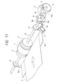
- a semi-circular portion is formed at the end of the rotary shaft 12 and a similar semi-circular hole is formed in the first notched gear 14.
- the first notched gear cannot slip on the rotary shaft during the rotation.
- a sheet supplying apparatus shown in Figs. 12 and 13 is similar to that shown in Fig. 11. However, in the sheet supplying apparatus shown in Figs. 12 and 13, a shaft portion 14b into which the semi-circular portion of the rotary shaft 12 is fitted is provided on the first notched gear 14, and the second notched gear 6 is rotatably mounted around the shaft portion 14b.
- the shaft portion 14b on the first notched gear 14 By providing the shaft portion 14b on the first notched gear 14 in this way, the adequate fitting length between the rotary shaft 12 and the first notched gear 14 which is subjected to great load during the rotation can be ensured without increasing a width of the first notched gear 14. That is to say, a width of the entire apparatus corresponding to the length of the shaft portion 14a can be reduced without reducing the securing strength between the first notched gear 14 and the rotary shaft 12, thereby making the apparatus compact.
- first notched gear 14, second notched gear 6 and spring 10 can be assembled as a single unit, the assembling ability of the sheet supplying apparatus can be improved.
- the drive controlling apparatus of the present invention during the operation of the sheet supply roller returning to its initial position after the sheet supplying operation is completed, when the first notched gear 14 is disengaged from the drive gear 4, as shown in Fig. 2B, it is necessary that the recesses 17a of the cams 17 are about to be engaged by the projections 16a of the intermediate plate 16, and, it is necessary that the first notched gear 14 is returned to the condition shown in Fig. 2A in which the recesses 17a of the cams 17 are completely engaged by the projections 16a. Accordingly, when the positional accuracy in the phase relation between the first notched gear 14 and the cam 17 is improved, the operating accuracy of the entire apparatus is also improved.
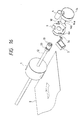
- a drive controlling apparatus therefor is similar to that shown in Figs. 12 and 13.
- the semi-circular roller is used as the sheet supply roller; whereas, in Fig. 16, a cylindrical sheet supply roller and a one-way clutch are used (as is in Fig. 10).
- cams and rollers can be omitted.
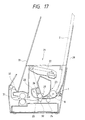
- Fig. 17 schematically shows an image forming apparatus to which the sheet supplying apparatus having the drive controlling apparatus can be applied.
- the image forming apparatus 21 comprises an optical system 22 for emitting laser light in response to image information, an image forming portion 23 including a photosensitive drum (image bearing member) 25, a first charger (corona discharger) 26, a developing device 27 and a cleaner 28, and a sheet convey portion for supplying, conveying and discharging a sheet.
- an optical system 22 for emitting laser light in response to image information
- an image forming portion 23 including a photosensitive drum (image bearing member) 25, a first charger (corona discharger) 26, a developing device 27 and a cleaner 28, and a sheet convey portion for supplying, conveying and discharging a sheet.
- a surface of the rotating photosensitive drum 25 having a photosensitive layer is uniformly charged by applying voltage to the first charger 26, and a latent image is formed on the photosensitive drum 25 by illuminating the laser light emitted from the optical system 22 in response to the image information through an exposure portion. Then, the latent image is developed by the developing device 27 as a toner image.
- a sheet 2 on a tray 29 is supplied by a sheet supply roller 1 forming a part of the sheet supplying apparatus driven by the drive controlling apparatus and is conveyed to the image forming portion 23 by a pair of convey rollers 24 and the like. Then, the toner image is transferred onto the sheet by applying voltage having polarity opposite to that of the toner image to a transfer roller 30. In the image forming portion 23, residual toner remaining on the photosensitive drum 25 is removed by the cleaner 28 for preparation for next image formation.
- the sheet to which the toner image was transferred is sent to a fixing roller 31 including a heater therein, where the toner image is fixed to the sheet. Thereafter, the sheet is discharged onto a tray 33 by a pair of discharge rollers 32.
- each of the notched gears has the single non-toothed portion
- two or more non-toothed portions may be provided on each notched gear.
- the drive controlling apparatus is used with the sheet supplying apparatus
- the present invention is not limited to such an example, the drive controlling apparatus can be used in synchronous with any functioning means for generating rotation of predetermined angle at a predetermined timing.
Landscapes
- Engineering & Computer Science (AREA)
- Mechanical Engineering (AREA)
- Sheets, Magazines, And Separation Thereof (AREA)
- Transmission Devices (AREA)
Claims (19)
- Appareil d'alimentation en feuilles comportant :dans lequel ledit moyen d'entraínement (4, 6) comporte une roue dentée (6) d'entraínement à laquelle la force d'entraínement est transmise par intermittence depuis ladite source de force d'entraínement, ledit moyen entraíné (12, 14) comporte un arbre (12) relié audit moyen (17) de séparation et également relié à un axe d'une roue dentée entraínée (14),un moyen montant/descendant (16) de support de feuilles destiné à supporter des feuilles (2) ;un moyen (1) d'alimentation en feuilles destiné à faire sortir la feuille (2) supportée par ledit moyen (16) de support de feuilles ;un moyen (16b) de rappel destiné à rappeler ledit moyen (16) de support de feuilles vers ledit moyen (1) d'alimentation en feuilles, la feuille (2) rappelée contre le moyen (1) d'alimentation en feuilles par ledit moyen de rappel (16b) étant sortie par ledit moyen (1) d'alimentation en feuilles ;un moyen (17) de séparation destiné à séparer ledit moyen de support de feuilles dudit moyen d'alimentation en feuilles en opposition à une force de rappel dudit moyen de rappel ; etun moyen de commande d'entraínement destiné à transmettre une force d'entraínement depuis une source de force d'entraínement audit moyen (17) de séparation, ledit moyen de commande d'entraínement comportant un moyen d'entraínement (4, 6) relié à ladite source de force d'entraínement et un moyen entraíné (12, 14) relié audit moyen (17) de séparation,
caractérisé par
un moyen (5, 10, 12a ; 6a, 14a) de réglage de jeu comportant un moyen de liaison (12a, 5 ; 6a, 14a) destiné à relier ladite roue dentée d'entraínement (6) et ledit arbre (12) ou ladite roue dentée entraínée (14) pour permettre un déplacement relatif dans une plage angulaire prédéterminée dans une direction de rotation dans une zone de liaison entre ladite roue dentée d'entraínement (6) et ledit arbre (12) ou ladite roue dentée entraínée (14) afin d'établir un jeu pour interrompre la transmission de ladite force de rappel dudit moyen de rappel (16b) audit moyen d'entraínement (4, 6) en interrompant la transmission de la force d'entraínement entre ledit moyen d'entraínement (4, 6) et ledit moyen entraíné (14) dans ladite plage angulaire prédéterminée, lors de la mise en marche du moyen (17) de séparation dans le fonctionnement. - Appareil d'alimentation en feuilles selon la revendication 1, dans lequel ledit moyen de liaison (12a, 5) comporte une rainure (5) formée dans ladite roue dentée d'entraínement (6) et une clavette (12a) formée sur ledit arbre (12), et ladite clavette (12a) est reçue dans ladite rainure (5) pour effectuer un mouvement de rotation dans une plage angulaire prédéterminée dans la direction de rotation.
- Appareil d'alimentation en feuilles selon la revendication 2, dans lequel la plage angulaire prédéterminée est choisie de façon à être une plage dans laquelle, lorsque ledit moyen (16) de support de feuilles est décalé vers ledit moyen (1) d'alimentation en feuilles par ledit moyen de rappel (16b) après que l'opération de séparation desdits moyens (17) de séparation a cessé, la force de rappel dudit moyen de rappel (16b) agissant sur ledit moyen (17) de séparation est diminuée.
- Appareil d'alimentation en feuilles selon la revendication 3, dans lequel ledit moyen (17) de séparation comporte une came (17) fixée audit arbre (12), et dans lequel, en outre, ledit moyen (16) de support de feuilles est séparé dudit moyen (1) d'alimentation en feuilles par l'abaissement dudit moyen (16) de support de feuilles par ladite came (17).
- Appareil d'alimentation en feuilles selon la revendication 1, dans lequel ladite roue dentée d'entraínement (6) est une roue dentée encochée ayant une partie non dentée, et comportant en outre un moyen de régulation (7) destiné à arrêter la rotation de ladite roue dentée encochée lorsque ladite partie non dentée est opposée à une autre roue dentée d'entraínement (4) dudit moyen d'entraínement (4, 6), cette autre roue dentée d'entraínement (4) recevant la force d'entraínement provenant de ladite source de force d'entraínement, la transmission de la force d'entraínement étant interrompue par ledit moyen (7) de régulation.
- Appareil d'alimentation en feuilles selon la revendication 5, comportant en outre un moyen (10) de rappel de roue dentée destiné à faire tourner temporairement ladite roue dentée encochée (6) pour l'engager avec ladite autre roue dentée d'entraínement (4) lorsque ledit moyen (7) de régulation est libéré.
- Appareil d'alimentation en feuilles selon la revendication 1, dans lequel ladite roue dentée entraínée (14) est une première roue dentée encochée (14) fixée audit arbre tournant (12) relié audit moyen (17) de séparation, un premier moyen de régulation (16a, 17a) destiné à arrêter ladite première roue dentée encochée (14) dans un état dans lequel une partie non dentée de ladite première roue dentée encochée (14) est opposée à une autre roue dentée d'entraínement (4) dudit moyen d'entraínement (4, 6), laquelle est reliée à ladite source de force d'entraínement, la roue dentée d'entraínement (6) étant une seconde roue dentée encochée (6) supportée de façon à pouvoir tourner sur ledit arbre tournant (12) et pouvant être engagée avec ladite autre roue dentée d'entraínement (4), un second moyen de régulation (7, 13) destiné à arrêter ladite seconde roue dentée encochée (6) dans un état dans lequel une partie non dentée de ladite seconde roue dentée encochée (6) est opposée à ladite autre roue dentée d'entraínement (4), un moyen (10) de rappel de roue dentée destiné à faire tourner ladite seconde roue dentée encochée (6) pour l'engager avec ladite autre roue dentée d'entraínement (4) lorsque ladite régulation dudit second moyen (7, 13) de régulation est libérée, ledit moyen de liaison (12a, 5) libérant la régulation dudit premier moyen (16a, 17a) de régulation pendant que ladite seconde roue dentée encochée (6) est en rotation tout en étant en engagement avec ladite autre roue dentée d'entraínement (4), faisant ainsi tourner ladite première roue dentée encochée (14) pour l'engager avec ladite autre roue dentée d'entraínement (4).
- Appareil d'alimentation en feuilles selon la revendication 7, dans lequel ledit moyen (17) de séparation comporte une came (17) séparant ledit moyen (16) de support de feuilles dudit moyen (1) d'alimentation en feuilles en opposition à une force de rappel dudit moyen de rappel (16b) par une rotation de ladite came (17).
- Appareil d'alimentation en feuilles selon la revendication 8, dans lequel ledit premier moyen de régulation (16a, 17a) présente un évidement (17a) situé sur l'un de ladite came (17) et dudit moyen (16) de support de feuilles, et une saillie (16a) située sur l'autre de ladite came (17) et dudit moyen (16) de support de feuilles, et dans lequel, en outre, un engagement entre ledit évidement (17a) et ladite saillie (16a) arrête ledit arbre tournant (12) pour réguler ladite première roue dentée encochée (14) .
- Appareil d'alimentation en feuilles selon la revendication 7, dans lequel ledit second moyen (7, 13) de régulation comporte une partie de verrouillage (13) située sur ladite seconde roue dentée encochée (6), et une bobine (7) ayant un cliquet de verrouillage (7a) pouvant être engagée et dégagée par rapport à ladite partie de verrouillage (13) et destinée à déplacer ledit cliquet de verrouillage (7a) vers une position d'engagement à une position de dégagement en réponse à une excitation et une désexcitation de ladite bobine (7).
- Appareil d'alimentation en feuilles selon la revendication 7, dans lequel ledit moyen de rappel (10) de roue dentée comporte un ressort (10) destiné à faire tourner ladite seconde roue dentée encochée (6) pour engager ladite seconde roue dentée encochée (6) avec ladite autre roue dentée d'entraínement (4) lorsque la régulation dudit second moyen (7, 13) de régulation est libérée.
- Appareil d'alimentation en feuilles selon la revendication 7, dans lequel ledit moyen de liaison (12a, 5) comporte une clavette (12a) située sur ledit arbre tournant (12) et une rainure (5) située dans ladite seconde roue dentée encochée (6), et ladite rainure (5) est dimensionnée de façon que ladite clavette (12a) puisse être déplacée à l'intérieur de ladite rainure (5) pour permettre une rotation de ladite seconde roue dentée encochée (6) par rapport audit arbre tournant (12) dans une plage prédéterminée.
- Appareil d'alimentation en feuilles selon la revendication 7, dans lequel ledit moyen (12a, 5) de liaison est positionné de façon que la rotation de ladite première roue dentée encochée (14) commence avec un temps de retard prédéterminé après que la rotation de ladite seconde roue dentée encochée (6) a commencé à la suite de la libération de la régulation dudit moyen (7, 13) de régulation, et ledit temps de retard est établi de façon que ladite seconde roue dentée encochée (6) ne soit pas mise en rotation avant qu'une force transmise depuis ledit moyen (16) de rappel audit moyen (17) de séparation ait diminué, lorsque la régulation dudit premier moyen (16a, 17a) de régulation est libérée par la rotation de ladite seconde roue dentée encochée (6).
- Appareil d'alimentation en feuilles selon la revendication 7, dans lequel lesdites première et seconde roues dentées encochées (14, 6) sont disposées côte à côte sur ledit arbre tournant (12), et une position relative entre lesdites première et seconde roues dentées encochées (14, 6) est régulée par ledit moyen de liaison (12a, 5) d'une manière telle que, lorsque la rotation de ladite première roue dentée encochée (14) commence, ladite seconde roue dentée encochée (6) soit engagée par ladite autre roue dentée d'entraínement (4) avec la même phase que ladite première roue dentée encochée (14).
- Appareil d'alimentation en feuilles selon la revendication 7, dans lequel ledit moyen (1) d'alimentation en feuilles comporte un rouleau situé sur ledit arbre tournant (12) et mis en rotation avec ledit arbre tournant (12) pour faire sortir la feuille.
- Appareil d'alimentation en feuilles selon la revendication 15, dans lequel ledit rouleau (1) est un rouleau semicirculaire ou un rouleau coupé, et comportant en outre un rouleau (3) disposé- au voisinage dudit rouleau coupé et monté de façon à pouvoir tourner sur ledit arbre tournant (12).
- Appareil d'alimentation en feuilles selon la revendication 15, dans lequel ledit rouleau (1) est un rouleau cylindrique, et comportant en outre une roue libre (19) disposée entre ledit rouleau cylindrique et ledit arbre tournant (12) afin que, même lorsque ledit arbre tournant (12) est arrêté par ladite roue libre (19) pendant que la feuille est en cours d'alimentation, la feuille en cours d'alimentation fasse tourner ledit rouleau cylindrique (1).
- Appareil d'alimentation en feuilles selon la revendication 7, dans lequel ledit moyen (16) de support de feuilles comporte une plaque intermédiaire pivotante destinée à supporter la feuille, et ledit moyen de rappel (16b) comporte un ressort destiné à rappeler ladite plaque intermédiaire vers ledit moyen (1) d'alimentation en feuilles.
- Appareil d'alimentation en feuilles selon l'une des revendications 1 à 18, dans lequel ledit appareil d'alimentation en feuilles est incorporé dans un appareil de formation d'images.
Applications Claiming Priority (6)
| Application Number | Priority Date | Filing Date | Title |
|---|---|---|---|
| JP27885096 | 1996-09-30 | ||
| JP278850/96 | 1996-09-30 | ||
| JP27885096 | 1996-09-30 | ||
| JP20989497 | 1997-07-18 | ||
| JP20989497A JP3517558B2 (ja) | 1996-09-30 | 1997-07-18 | 駆動制御装置及びシート給送装置及び画像形成装置 |
| JP209894/97 | 1997-07-18 |
Publications (3)
| Publication Number | Publication Date |
|---|---|
| EP0832833A2 EP0832833A2 (fr) | 1998-04-01 |
| EP0832833A3 EP0832833A3 (fr) | 1998-12-09 |
| EP0832833B1 true EP0832833B1 (fr) | 2002-04-03 |
Family
ID=26517733
Family Applications (1)
| Application Number | Title | Priority Date | Filing Date |
|---|---|---|---|
| EP97116874A Expired - Lifetime EP0832833B1 (fr) | 1996-09-30 | 1997-09-29 | Appareil d'alimentation de feuilles |
Country Status (5)
| Country | Link |
|---|---|
| US (1) | US6070867A (fr) |
| EP (1) | EP0832833B1 (fr) |
| JP (1) | JP3517558B2 (fr) |
| CN (1) | CN1089694C (fr) |
| DE (1) | DE69711525T2 (fr) |
Cited By (1)
| Publication number | Priority date | Publication date | Assignee | Title |
|---|---|---|---|---|
| US8523172B2 (en) | 2010-12-24 | 2013-09-03 | Canon Kabushiki Kaisha | Image forming apparatus |
Families Citing this family (57)
| Publication number | Priority date | Publication date | Assignee | Title |
|---|---|---|---|---|
| JP2000044072A (ja) * | 1998-07-30 | 2000-02-15 | Brother Ind Ltd | 給紙装置 |
| EP1053961B1 (fr) * | 1999-05-14 | 2006-06-14 | Canon Kabushiki Kaisha | Appareil de formation d'images |
| RU2154613C1 (ru) * | 1999-06-21 | 2000-08-20 | Байкальский институт природопользования СО РАН | Способ очистки сточных вод от цианидов и роданидов |
| US6547236B1 (en) * | 2000-01-05 | 2003-04-15 | Hewlett-Packard Company | Pick-up mechanism and a method for performing a pick-up cycle in a reproduction machine |
| US6502816B2 (en) | 2000-03-13 | 2003-01-07 | Canon Kabushiki Kaisha | Sheet feeding apparatus and image forming apparatus having same |
| JP2001335168A (ja) | 2000-05-24 | 2001-12-04 | Canon Inc | シート供給装置とこの装置を備えた画像形成装置 |
| JP3733841B2 (ja) * | 2000-07-06 | 2006-01-11 | セイコーエプソン株式会社 | シート供給装置 |
| DE60123712T2 (de) * | 2000-08-08 | 2007-08-16 | Ricoh Co., Ltd. | Blattzuführverfahren und Vorrichtung für eine Bilderzeugungsvorrichtung |
| JP2003040472A (ja) * | 2001-07-31 | 2003-02-13 | Ricoh Co Ltd | 給紙機構及びそれを備えた画像形成装置 |
| US6655679B2 (en) * | 2002-01-31 | 2003-12-02 | Hewlett-Packard Development Company, L.P. | Input converger for hardcopy devices |
| JP2003300637A (ja) | 2002-04-11 | 2003-10-21 | Canon Inc | シート作用部材及びこれを用いたシート搬送装置並びに画像処理装置 |
| JP3782760B2 (ja) * | 2002-07-12 | 2006-06-07 | キヤノン株式会社 | シート給送装置及びこれを備えた画像形成装置 |
| CN100368207C (zh) * | 2002-08-20 | 2008-02-13 | 夏普株式会社 | 送纸装置以及具有该送纸装置的图像形成装置 |
| JP4139958B2 (ja) * | 2002-09-30 | 2008-08-27 | ブラザー工業株式会社 | 回転クラッチ装置、給紙装置及び画像形成装置 |
| US7090215B2 (en) * | 2003-06-16 | 2006-08-15 | Xerox Corporation | Printer paper path plural nips releasing system |
| JP4006366B2 (ja) * | 2003-07-02 | 2007-11-14 | キヤノン株式会社 | シート給送装置及び画像形成装置 |
| JP2005029296A (ja) * | 2003-07-08 | 2005-02-03 | Konica Minolta Business Technologies Inc | 動力伝達装置及び給紙装置 |
| TWI220412B (en) * | 2003-11-11 | 2004-08-21 | Benq Corp | Guiding and positioning apparatus |
| KR100524078B1 (ko) * | 2003-11-18 | 2005-10-26 | 삼성전자주식회사 | 자동원고이송장치 |
| JP4218509B2 (ja) * | 2003-11-26 | 2009-02-04 | 富士ゼロックス株式会社 | シート材給送装置 |
| CN1332816C (zh) * | 2003-12-17 | 2007-08-22 | 明基电通股份有限公司 | 导正输入方法及导正方法 |
| US6991392B2 (en) * | 2004-01-08 | 2006-01-31 | Xerox Corporation | Door assembly having a print media delivery system |
| JP4401789B2 (ja) * | 2004-01-23 | 2010-01-20 | キヤノン株式会社 | シート給送ユニットおよび画像形成装置 |
| US7232124B2 (en) * | 2004-06-03 | 2007-06-19 | Hewlett-Packard Development Company, L.P. | Sheet separator |
| ITTO20040526A1 (it) | 2004-07-28 | 2004-10-28 | Olivetti Tecnost Spa | Dispositivo a struttura compatta per il prelievo di fogli da due cassetti, relativa stampante |
| KR100561441B1 (ko) * | 2004-08-09 | 2006-03-17 | 삼성전자주식회사 | 용지픽업장치 및 이를 구비한 화상형성장치 |
| KR100831323B1 (ko) * | 2004-10-02 | 2008-05-22 | 삼성전자주식회사 | 용지픽업유닛 및 이를 갖는 화상형성장치 |
| JP4006432B2 (ja) * | 2004-11-12 | 2007-11-14 | キヤノン株式会社 | シート給送装置及び画像形成装置 |
| JP2006240859A (ja) * | 2005-03-07 | 2006-09-14 | Kyocera Mita Corp | 給紙装置 |
| TWI253391B (en) * | 2005-05-13 | 2006-04-21 | Benq Corp | A paper pick-up module of a printer of the like |
| TW200800633A (en) * | 2006-06-16 | 2008-01-01 | Primax Electronics Ltd | Pick-up apparatus |
| JP4819622B2 (ja) * | 2006-08-30 | 2011-11-24 | キヤノン株式会社 | シート給送装置及び画像形成装置 |
| KR20080027619A (ko) * | 2006-09-25 | 2008-03-28 | 삼성전자주식회사 | 용지 픽업유닛 및 이를 구비한 화상형성장치 |
| TWI316471B (en) * | 2006-12-19 | 2009-11-01 | Teco Image Sys Co Ltd | Differential apparatus in paper separation |
| KR20080095055A (ko) * | 2007-04-23 | 2008-10-28 | 삼성전자주식회사 | 레버 조립체, 이를 구비한 화상형성장치 및 이에 사용되는솔레노이드 |
| JP2009057170A (ja) * | 2007-08-31 | 2009-03-19 | Ricoh Co Ltd | シート給送装置、及びそのシート給送装置を備える画像形成装置 |
| JP5142874B2 (ja) * | 2008-07-30 | 2013-02-13 | キヤノン株式会社 | 画像形成装置 |
| JP2010202379A (ja) | 2009-03-05 | 2010-09-16 | Ricoh Co Ltd | 給紙装置、画像形成装置 |
| CN102189832A (zh) * | 2010-03-17 | 2011-09-21 | 鸿富锦精密工业(深圳)有限公司 | 打印机取纸机构 |
| US8511671B2 (en) * | 2010-06-28 | 2013-08-20 | Canon Kabushiki Kaisha | Sheet feeding apparatus and image forming apparatus |
| JP5606291B2 (ja) * | 2010-06-28 | 2014-10-15 | キヤノン株式会社 | シート給送装置及び画像形成装置 |
| HUE028107T2 (en) * | 2011-07-13 | 2016-11-28 | Sca Hygiene Prod Ab | Adhesive Product Dispenser and Rack |
| JP5930809B2 (ja) | 2012-04-05 | 2016-06-08 | キヤノン株式会社 | シート給送装置及び画像形成装置 |
| US9121475B2 (en) | 2012-05-02 | 2015-09-01 | Canon Kabushiki Kaisha | Drive transmission apparatus and image forming apparatus |
| EP2911566B1 (fr) * | 2012-10-26 | 2020-10-14 | Essity Hygiene and Health Aktiebolag | Distributeur comprenant une unité de séparation |
| US10058221B2 (en) | 2012-10-26 | 2018-08-28 | Sca Hygiene Products Ab | Dispenser |
| US10390664B2 (en) | 2012-10-26 | 2019-08-27 | Essity Hygiene And Health Aktiebolag | Separation unit and a dispenser comprising a separation unit |
| CN103660618B (zh) * | 2013-11-21 | 2015-10-21 | 浙江大学 | 便捷取纸装置 |
| JP6291807B2 (ja) * | 2013-11-25 | 2018-03-14 | 株式会社リコー | 給紙装置および画像形成装置 |
| EP3136926B1 (fr) | 2014-04-28 | 2022-08-10 | Essity Hygiene and Health Aktiebolag | Distributeur |
| US10155634B2 (en) | 2015-05-29 | 2018-12-18 | Canon Kabushiki Kaisha | Sheet feeding apparatus, image reading apparatus, and image forming apparatus |
| CN105606361B (zh) * | 2016-01-28 | 2019-02-19 | 上海交通大学 | 可调间隙实验平台 |
| US10183823B2 (en) * | 2016-03-18 | 2019-01-22 | Hewlett-Packard Development Company, L.P. | Lift mechanisms |
| JP7066356B2 (ja) * | 2017-08-30 | 2022-05-13 | キヤノン株式会社 | 現像装置 |
| CN108423416B (zh) * | 2018-03-21 | 2019-08-16 | 潍坊学院 | 散热器翅片分离取送设备 |
| CN110040395B (zh) * | 2019-04-22 | 2022-03-11 | 广州广电运通金融电子股份有限公司 | 一种纸张类介质回收存储盒 |
| CN114242443A (zh) * | 2021-11-09 | 2022-03-25 | 天威保变(秦皇岛)变压器有限公司 | 一种大型变压器整体套装绝缘纸带绕制装置及使用方法 |
Family Cites Families (5)
| Publication number | Priority date | Publication date | Assignee | Title |
|---|---|---|---|---|
| JPH02193830A (ja) * | 1989-01-20 | 1990-07-31 | Konica Corp | 給紙装置 |
| US5240242A (en) * | 1990-07-05 | 1993-08-31 | Canon Kabushiki Kaisha | Sheet feeding device |
| US5358230A (en) * | 1992-04-24 | 1994-10-25 | Canon Kabushiki Kaisha | Sheet supplying apparatus |
| JPH08225157A (ja) * | 1995-02-17 | 1996-09-03 | Sankuru:Kk | 物品の移送装置 |
| JP2883829B2 (ja) * | 1995-02-20 | 1999-04-19 | キヤノン株式会社 | シート給送装置および画像形成装置 |
-
1997
- 1997-07-18 JP JP20989497A patent/JP3517558B2/ja not_active Expired - Fee Related
- 1997-09-23 US US08/932,776 patent/US6070867A/en not_active Expired - Lifetime
- 1997-09-29 DE DE69711525T patent/DE69711525T2/de not_active Expired - Lifetime
- 1997-09-29 EP EP97116874A patent/EP0832833B1/fr not_active Expired - Lifetime
- 1997-09-30 CN CN97121461A patent/CN1089694C/zh not_active Expired - Fee Related
Cited By (1)
| Publication number | Priority date | Publication date | Assignee | Title |
|---|---|---|---|---|
| US8523172B2 (en) | 2010-12-24 | 2013-09-03 | Canon Kabushiki Kaisha | Image forming apparatus |
Also Published As
| Publication number | Publication date |
|---|---|
| DE69711525T2 (de) | 2002-10-17 |
| EP0832833A3 (fr) | 1998-12-09 |
| CN1089694C (zh) | 2002-08-28 |
| HK1009431A1 (en) | 1999-06-04 |
| CN1179386A (zh) | 1998-04-22 |
| DE69711525D1 (de) | 2002-05-08 |
| US6070867A (en) | 2000-06-06 |
| JPH10153247A (ja) | 1998-06-09 |
| JP3517558B2 (ja) | 2004-04-12 |
| EP0832833A2 (fr) | 1998-04-01 |
Similar Documents
| Publication | Publication Date | Title |
|---|---|---|
| EP0832833B1 (fr) | Appareil d'alimentation de feuilles | |
| EP0888988B1 (fr) | Appareil pour alimenter des feuilles | |
| KR20000029070A (ko) | 시트 공급 장치, 이를 갖는 화상 형성 장치 및 화상 판독장치 | |
| KR100334594B1 (ko) | 시트 공급 장치, 이를 갖는 화상 형성 장치 및 화상 판독 장치 | |
| JP4139958B2 (ja) | 回転クラッチ装置、給紙装置及び画像形成装置 | |
| US6578840B1 (en) | Sheet conveying apparatus | |
| JP3598192B2 (ja) | 駆動装置 | |
| JPH08225167A (ja) | シート給送装置および画像形成装置 | |
| US7448623B2 (en) | Paper feeding mechanism and image forming apparatus employing the same | |
| JP2021011907A (ja) | 駆動伝達装置及びそれを備える画像形成装置 | |
| US5711405A (en) | Spring clutch mechanism and a clutch mechanism for use in a paper feeding apparatus | |
| HK1009431B (en) | Sheet supplying apparatus | |
| JP2003312868A (ja) | 駆動制御装置及びシート給送装置及び画像形成装置 | |
| JP2001348130A (ja) | 用紙搬送装置および原稿読取装置ならびに画像形成装置 | |
| JP6000572B2 (ja) | シート給送装置及び画像形成装置 | |
| JPH09278205A (ja) | 給紙装置 | |
| JP3459695B2 (ja) | シート給送装置及び該シート給送装置を備えた画像形成装置 | |
| JP2966741B2 (ja) | 給紙装置 | |
| JP3931371B2 (ja) | クラッチ機構 | |
| JPH0577951A (ja) | 給紙装置 | |
| US11834292B2 (en) | Driving force transmission device and image forming apparatus | |
| JP2813044B2 (ja) | シート材給送装置 | |
| JP3791327B2 (ja) | 動力伝達装置、給紙装置及び画像形成装置 | |
| JP3557057B2 (ja) | 駆動装置 | |
| JPH115641A (ja) | 駆動伝達装置および給送装置および画像形成装置 |
Legal Events
| Date | Code | Title | Description |
|---|---|---|---|
| PUAI | Public reference made under article 153(3) epc to a published international application that has entered the european phase |
Free format text: ORIGINAL CODE: 0009012 |
|
| AK | Designated contracting states |
Kind code of ref document: A2 Designated state(s): DE FR GB IT |
|
| PUAL | Search report despatched |
Free format text: ORIGINAL CODE: 0009013 |
|
| AK | Designated contracting states |
Kind code of ref document: A3 Designated state(s): AT BE CH DE DK ES FI FR GB GR IE IT LI LU MC NL PT SE |
|
| 17P | Request for examination filed |
Effective date: 19990426 |
|
| 17Q | First examination report despatched |
Effective date: 19990615 |
|
| AKX | Designation fees paid |
Free format text: DE FR GB IT |
|
| GRAG | Despatch of communication of intention to grant |
Free format text: ORIGINAL CODE: EPIDOS AGRA |
|
| GRAG | Despatch of communication of intention to grant |
Free format text: ORIGINAL CODE: EPIDOS AGRA |
|
| GRAH | Despatch of communication of intention to grant a patent |
Free format text: ORIGINAL CODE: EPIDOS IGRA |
|
| REG | Reference to a national code |
Ref country code: GB Ref legal event code: IF02 |
|
| GRAH | Despatch of communication of intention to grant a patent |
Free format text: ORIGINAL CODE: EPIDOS IGRA |
|
| GRAA | (expected) grant |
Free format text: ORIGINAL CODE: 0009210 |
|
| AK | Designated contracting states |
Kind code of ref document: B1 Designated state(s): DE FR GB IT |
|
| REF | Corresponds to: |
Ref document number: 69711525 Country of ref document: DE Date of ref document: 20020508 |
|
| ET | Fr: translation filed | ||
| PLBE | No opposition filed within time limit |
Free format text: ORIGINAL CODE: 0009261 |
|
| STAA | Information on the status of an ep patent application or granted ep patent |
Free format text: STATUS: NO OPPOSITION FILED WITHIN TIME LIMIT |
|
| 26N | No opposition filed |
Effective date: 20030106 |
|
| PGFP | Annual fee paid to national office [announced via postgrant information from national office to epo] |
Ref country code: IT Payment date: 20100914 Year of fee payment: 14 Ref country code: FR Payment date: 20101004 Year of fee payment: 14 |
|
| PG25 | Lapsed in a contracting state [announced via postgrant information from national office to epo] |
Ref country code: IT Free format text: LAPSE BECAUSE OF NON-PAYMENT OF DUE FEES Effective date: 20110929 |
|
| REG | Reference to a national code |
Ref country code: FR Ref legal event code: ST Effective date: 20120531 |
|
| PG25 | Lapsed in a contracting state [announced via postgrant information from national office to epo] |
Ref country code: FR Free format text: LAPSE BECAUSE OF NON-PAYMENT OF DUE FEES Effective date: 20110930 |
|
| PGFP | Annual fee paid to national office [announced via postgrant information from national office to epo] |
Ref country code: GB Payment date: 20150922 Year of fee payment: 19 Ref country code: DE Payment date: 20150930 Year of fee payment: 19 |
|
| REG | Reference to a national code |
Ref country code: DE Ref legal event code: R119 Ref document number: 69711525 Country of ref document: DE |
|
| GBPC | Gb: european patent ceased through non-payment of renewal fee |
Effective date: 20160929 |
|
| PG25 | Lapsed in a contracting state [announced via postgrant information from national office to epo] |
Ref country code: DE Free format text: LAPSE BECAUSE OF NON-PAYMENT OF DUE FEES Effective date: 20170401 Ref country code: GB Free format text: LAPSE BECAUSE OF NON-PAYMENT OF DUE FEES Effective date: 20160929 |