EP0832852A2 - Procédé pour la dégradation de matières nuisibles - Google Patents
Procédé pour la dégradation de matières nuisibles Download PDFInfo
- Publication number
- EP0832852A2 EP0832852A2 EP97116376A EP97116376A EP0832852A2 EP 0832852 A2 EP0832852 A2 EP 0832852A2 EP 97116376 A EP97116376 A EP 97116376A EP 97116376 A EP97116376 A EP 97116376A EP 0832852 A2 EP0832852 A2 EP 0832852A2
- Authority
- EP
- European Patent Office
- Prior art keywords
- container part
- reactor
- persulfate
- heat transfer
- aqueous solution
- Prior art date
- Legal status (The legal status is an assumption and is not a legal conclusion. Google has not performed a legal analysis and makes no representation as to the accuracy of the status listed.)
- Withdrawn
Links
Images



Classifications
-
- B—PERFORMING OPERATIONS; TRANSPORTING
- B01—PHYSICAL OR CHEMICAL PROCESSES OR APPARATUS IN GENERAL
- B01J—CHEMICAL OR PHYSICAL PROCESSES, e.g. CATALYSIS OR COLLOID CHEMISTRY; THEIR RELEVANT APPARATUS
- B01J3/00—Processes of utilising sub-atmospheric or super-atmospheric pressure to effect chemical or physical change of matter; Apparatus therefor
-
- B—PERFORMING OPERATIONS; TRANSPORTING
- B01—PHYSICAL OR CHEMICAL PROCESSES OR APPARATUS IN GENERAL
- B01J—CHEMICAL OR PHYSICAL PROCESSES, e.g. CATALYSIS OR COLLOID CHEMISTRY; THEIR RELEVANT APPARATUS
- B01J19/00—Chemical, physical or physico-chemical processes in general; Their relevant apparatus
- B01J19/0006—Controlling or regulating processes
- B01J19/0013—Controlling the temperature of the process
-
- C—CHEMISTRY; METALLURGY
- C02—TREATMENT OF WATER, WASTE WATER, SEWAGE, OR SLUDGE
- C02F—TREATMENT OF WATER, WASTE WATER, SEWAGE, OR SLUDGE
- C02F1/00—Treatment of water, waste water, or sewage
- C02F1/30—Treatment of water, waste water, or sewage by irradiation
- C02F1/302—Treatment of water, waste water, or sewage by irradiation with microwaves
-
- C—CHEMISTRY; METALLURGY
- C02—TREATMENT OF WATER, WASTE WATER, SEWAGE, OR SLUDGE
- C02F—TREATMENT OF WATER, WASTE WATER, SEWAGE, OR SLUDGE
- C02F1/00—Treatment of water, waste water, or sewage
- C02F1/30—Treatment of water, waste water, or sewage by irradiation
- C02F1/32—Treatment of water, waste water, or sewage by irradiation with ultraviolet light
-
- C—CHEMISTRY; METALLURGY
- C02—TREATMENT OF WATER, WASTE WATER, SEWAGE, OR SLUDGE
- C02F—TREATMENT OF WATER, WASTE WATER, SEWAGE, OR SLUDGE
- C02F1/00—Treatment of water, waste water, or sewage
- C02F1/34—Treatment of water, waste water, or sewage with mechanical oscillations
- C02F1/36—Treatment of water, waste water, or sewage with mechanical oscillations ultrasonic vibrations
-
- C—CHEMISTRY; METALLURGY
- C02—TREATMENT OF WATER, WASTE WATER, SEWAGE, OR SLUDGE
- C02F—TREATMENT OF WATER, WASTE WATER, SEWAGE, OR SLUDGE
- C02F1/00—Treatment of water, waste water, or sewage
- C02F1/72—Treatment of water, waste water, or sewage by oxidation
- C02F1/722—Oxidation by peroxides
-
- C—CHEMISTRY; METALLURGY
- C02—TREATMENT OF WATER, WASTE WATER, SEWAGE, OR SLUDGE
- C02F—TREATMENT OF WATER, WASTE WATER, SEWAGE, OR SLUDGE
- C02F1/00—Treatment of water, waste water, or sewage
- C02F1/72—Treatment of water, waste water, or sewage by oxidation
- C02F1/725—Treatment of water, waste water, or sewage by oxidation by catalytic oxidation
-
- B—PERFORMING OPERATIONS; TRANSPORTING
- B01—PHYSICAL OR CHEMICAL PROCESSES OR APPARATUS IN GENERAL
- B01J—CHEMICAL OR PHYSICAL PROCESSES, e.g. CATALYSIS OR COLLOID CHEMISTRY; THEIR RELEVANT APPARATUS
- B01J2219/00—Chemical, physical or physico-chemical processes in general; Their relevant apparatus
- B01J2219/00049—Controlling or regulating processes
- B01J2219/00051—Controlling the temperature
- B01J2219/00054—Controlling or regulating the heat exchange system
- B01J2219/00056—Controlling or regulating the heat exchange system involving measured parameters
- B01J2219/00067—Liquid level measurement
-
- B—PERFORMING OPERATIONS; TRANSPORTING
- B01—PHYSICAL OR CHEMICAL PROCESSES OR APPARATUS IN GENERAL
- B01J—CHEMICAL OR PHYSICAL PROCESSES, e.g. CATALYSIS OR COLLOID CHEMISTRY; THEIR RELEVANT APPARATUS
- B01J2219/00—Chemical, physical or physico-chemical processes in general; Their relevant apparatus
- B01J2219/00049—Controlling or regulating processes
- B01J2219/00051—Controlling the temperature
- B01J2219/00074—Controlling the temperature by indirect heating or cooling employing heat exchange fluids
- B01J2219/00087—Controlling the temperature by indirect heating or cooling employing heat exchange fluids with heat exchange elements outside the reactor
- B01J2219/00094—Jackets
-
- B—PERFORMING OPERATIONS; TRANSPORTING
- B01—PHYSICAL OR CHEMICAL PROCESSES OR APPARATUS IN GENERAL
- B01J—CHEMICAL OR PHYSICAL PROCESSES, e.g. CATALYSIS OR COLLOID CHEMISTRY; THEIR RELEVANT APPARATUS
- B01J2219/00—Chemical, physical or physico-chemical processes in general; Their relevant apparatus
- B01J2219/00049—Controlling or regulating processes
- B01J2219/00051—Controlling the temperature
- B01J2219/00074—Controlling the temperature by indirect heating or cooling employing heat exchange fluids
- B01J2219/00105—Controlling the temperature by indirect heating or cooling employing heat exchange fluids part or all of the reactants being heated or cooled outside the reactor while recycling
- B01J2219/00108—Controlling the temperature by indirect heating or cooling employing heat exchange fluids part or all of the reactants being heated or cooled outside the reactor while recycling involving reactant vapours
-
- B—PERFORMING OPERATIONS; TRANSPORTING
- B01—PHYSICAL OR CHEMICAL PROCESSES OR APPARATUS IN GENERAL
- B01J—CHEMICAL OR PHYSICAL PROCESSES, e.g. CATALYSIS OR COLLOID CHEMISTRY; THEIR RELEVANT APPARATUS
- B01J2219/00—Chemical, physical or physico-chemical processes in general; Their relevant apparatus
- B01J2219/00049—Controlling or regulating processes
- B01J2219/00051—Controlling the temperature
- B01J2219/0015—Controlling the temperature by thermal insulation means
- B01J2219/00155—Controlling the temperature by thermal insulation means using insulating materials or refractories
-
- B—PERFORMING OPERATIONS; TRANSPORTING
- B01—PHYSICAL OR CHEMICAL PROCESSES OR APPARATUS IN GENERAL
- B01J—CHEMICAL OR PHYSICAL PROCESSES, e.g. CATALYSIS OR COLLOID CHEMISTRY; THEIR RELEVANT APPARATUS
- B01J2219/00—Chemical, physical or physico-chemical processes in general; Their relevant apparatus
- B01J2219/00049—Controlling or regulating processes
- B01J2219/00051—Controlling the temperature
- B01J2219/00159—Controlling the temperature controlling multiple zones along the direction of flow, e.g. pre-heating and after-cooling
-
- B—PERFORMING OPERATIONS; TRANSPORTING
- B01—PHYSICAL OR CHEMICAL PROCESSES OR APPARATUS IN GENERAL
- B01J—CHEMICAL OR PHYSICAL PROCESSES, e.g. CATALYSIS OR COLLOID CHEMISTRY; THEIR RELEVANT APPARATUS
- B01J2219/00—Chemical, physical or physico-chemical processes in general; Their relevant apparatus
- B01J2219/00049—Controlling or regulating processes
- B01J2219/00177—Controlling or regulating processes controlling the pH
Definitions
- the invention relates to a method for breaking down pollutants from waste water, process solutions and drinking water using of persulfate.
- the spectrum of anthropogenic pollutants in aqueous solutions is broad. There are therefore a whole range of processes that deal with the treatment of aqueous solutions.
- the main aim is to remove organohalogen compounds, organic carbon and COD concentrations from industrial and municipal wastewater or chemical, pharmaceutical or galvanic process solutions.
- Another goal is the oxidation of environmental toxins such as CN - , heavy metal cyanide complexes, NH 4 + and H 2 S.
- the deodorization and decolorization of waste water is aimed for.
- the limits for TOCs are drafted in such a way that they prevent chemical-physical Parameters e.g. the affected natural Surface waters change so much that their ecosystem is seriously changed. For example, a high proportion of oxidizable substances lowering the Water present oxygen concentration and thus the death of aerobic organisms. (COD value)
- peroxodisulfate is used in addition to technical applications in the electroplating and printed circuit board industry and as a radical starter for polymerizations also in analytics for determination of the DOC (dissolved organic carbon) or TOC used as a reagent in various Syntheses.
- a particularly great disadvantage is that in the presence of Chlorides in the aqueous solutions to be treated when used of peroxodisulfate as an oxidizing agent organochlorine Connections are formed. At higher required Concentrations of peroxodisulfates can exceed it in addition, in the presence of chlorides, even chlorine emissions come.
- the pH range to be set may vary depending on the solution to the problem lie between 0 and 14 and thus covers the entire pH range as opposed to previous systems that work in a certain, usually alkaline pH range were.
- the temperature is not so high that it is expensive Equipment would be necessary, as is the case with some Process is necessary that work at temperatures above 300 ° C.
- the present invention also enables the method to drive continuously.
- a Conti reactor type proposed, in which the incoming, untreated and cold wastewater through the spilled, treated and therefore preheated warm waste water in countercurrent is so that the energy costs are minimized. It should a dwell time of approx. 100 seconds at 130 ° C is guaranteed be the reactor size in proportion to the treated wastewater to keep as low as possible.
- Steam, waste heat, e.g. name is Gases, organic heat transfer media and resistance heating in question.
- Internals can be provided in the reaction space guarantee a better heat transfer to the reactor wall and at the same time prevent undesired vertical cross-mixing. These internals should be designed so that they Allow any gas to escape upwards can. Since the internals have good heat transfer as possible should have, they can be straight pipes, coils or plates, but also a simple one Filling with ceramic Raschig rings is possible.
- the wastewater outlet should an overflow valve may be installed depending on the desired reactor pressure set to a certain discharge pressure can be.
- the formation of gases would cause the Reactor are gradually emptied and the residence time would shorten.
- the upper part of the Reactor head a point level detector to be mounted. Detected this one gas phase, switches the gas overflow valve downstream shut-off valve on and the waste water outlet overflow valve downstream shut-off valve at the same time to. Via the second overflow valve in the gas line Gas now escapes until the point level detector again detects a liquid phase. In this state, the gas shut-off valve closes and opens the waste water shut-off valve. There given the escape of the gas, a pressure drop in the reactor opening of the gas shut-off valve should be additional limited to a preset minimum reactor pressure will.
- the method according to the invention is not based on the use limited in the device described above, but can e.g. also with a classic tube reactor using the Contiver process or in a normal pressure vessel in batches be driven.
- Peroxodisulfates are suitable as active oxidation components, Peroxomonosulfate and mixtures of Peroxodisulfaten or Peroxomonosulfates with percarbonates and perborates.
- a mixture of one Peroxodisulfate used with hydrogen peroxide preferably in a molar ratio of 0.1 to 2.0 moles of hydrogen peroxide per mole of peroxodisulfate.
- the addition of hydrogen peroxide leads to a further acceleration of the process and opens up a possibility of the amounts of persulfate used decrease since the hydrogen peroxide and its decay has an activating effect on the oxidizing ability of the peroxodisulfate.
- the hydrogen peroxide is preferably in the form of sodium carbonate peroxohydrate brought in.
- the preferred residence times according to the present invention are between 30 in a preferred embodiment and 500 sec. in a very preferred embodiment between 80 and 300 sec. and with the particularly preferred Embodiment at about 100 sec.
- the preferred dwell times ensure an almost 100 % degradation of the impurities in the aqueous Solutions.
- the method according to the present invention can be used with any Pressure that is greater than 1 bar, i.e. also the process can be operated at very low pressures. Usually the pressure is chosen so that the applied temperature suppresses the boiling of the liquid becomes.
- the rate of decomposition of the persulfate decreases as the pH value increases and therefore even shorter dwell times in the reactor, it also makes sense the pH in the reactor to a slightly alkaline level hold. This can be accomplished by e.g. several Alkaline additions can be installed in the reaction area. This keeps the pH in a narrow pH window.
- the added alkalis are the hydroxides, carbonates and / or Hydrogen carbonates of sodium or potassium are conceivable.
- Additives or fixed bed fillings can be used as catalysts of coal or graphite powder or granulate in question come or also additives or fixed bed fillings of adsorber resin.
- Transition metals used as a catalyst In a particularly preferred embodiment Transition metals used as a catalyst.
- Fixing the catalysts is particularly preferred Activated carbon.
- the degradation reactions can also be accelerated by simultaneous irradiation with UV, microwave or ultrasound be achieved.
- Another object of the invention is a device for carrying out the method according to one of claims 1 to 22, comprising a device for the removal of impurities in aqueous solutions using persulfate, with a first container part for receiving the aqueous solution, which has an inlet and an outlet and a reaction space forms, with a heating device for heating the aqueous solution is provided, further heat transfer means are provided, the heat transfer between the Allow heater and aqueous solution, and wherein at least one pressure generating means is provided.
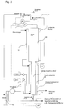
- a reactor type 10 for the continuous process is shown schematically in FIG.
- the untreated wastewater 12 is pumped into a heat exchanger 16 using a feed pump 14 and is conveyed in the direction of the reactor interior.
- the wastewater 12 absorbs the heat from the hot wastewater 18 which has already been treated and which thereby cools down at the same time.
- the preheated waste water 12 runs into the reactor 20 and heats up there to the desired temperature.
- This circuit guarantees a very low energy requirement for the process, so that even larger amounts of wastewater can be managed without a greater energy requirement (example 4).
- Installation in the reactor 20 results in better heat transfer to the reactor wall and, at the same time, prevents undesirable vertical cross-mixing.
- the internals should be designed in such a way that any gas that arises can freely escape upwards. Since the internals should have as good a heat transfer as possible, they can be designed as straight pipes, coils, plates, but also simple fillings with ceramic Raschig rings bring a positive effect.
- an overflow valve is installed before the wastewater outlet, which can be adjusted to a specific discharge pressure depending on the desired reactor pressure. The formation of CO 2 / N 2 / O 2 gases would gradually empty the reactor and shorten the residence time. In this case, a level detector is installed in the upper part of the reactor head.
- the shut-off valve downstream of the gas overflow valve and the shut-off valve downstream of the wastewater outlet overflow valve switch on simultaneously. Gas now escapes via the second overflow valve in the gas line until the point level detector detects a liquid phase again. In this state, the gas shut-off valve closes and the waste water outlet shut-off valve opens. Since there can be a pressure drop in the reactor when the gas escapes and thus gas expansion takes place at the same time, the opening of the gas shut-off valve is additionally limited to a preset minimum reactor pressure. This pendulum circuit enables trouble-free operation even in very low pressure ranges (e.g. 1 - 6 bar). Which has a cost-effective effect on the components for the process. The energy costs can be further minimized by an optimized preheating exchange. Values of ⁇ 10 KWh / m 3 wastewater can be achieved when using plate heat exchangers in example 4.
- reactor tubes e.g. from PFA; PTFE etc. used will. If the pressure in the "pressurized water” and in the reactor inner tube is kept the same.
- the reactor outer tube can be very cheap materials. It's just that Preheater and the line from the preheater into the reactor corrosion-resistant (expensive) materials.
- This schematic representation can of course in form and type of heating vary. You can also use one instead of "pressurized water” use another pressurized heat transfer medium.
- the heated internal volume of the reactor was 75 ml Rohrwendel was in an oil bath thermostat that opened 135 ° C was heated. After the oil bath, the contents of the Tube cooled to room temperature with water cooling. In order to maintain a constant pressure in the Preserving the reactor was a presettable overflow valve installed at the end of the pipe.
- the pressure of the reactor was kept between 8-9 bar.
- the pipe was filled with Raschig rings in the heated area.
- the solution was between the metering pump and the reactor section a pipe section in an oil bath thermostat at 110 ° C submerged.
- the internal volume of the reactor was 93 ml Inlets and outlets of the reactor had an inner tube diameter of 4 mm.
- At the bottom outlet - the solution was for cooling a piece of pipe submerged in a water bath.
- At the end This piece of pipe had an overflow valve that was set to 6 bar was set.
- a thermocouple was used to control the temperature installed in the lower third of the reactor.
- Around to be able to maintain a constant reactor level in a 5 cm long DN 15 flanged to the reactor head Pipe section two conductive level indicators and a needle valve installed above the upper sensor. When reporting a Gaseous phase through the lower sensor was carefully the needle valve opened until the upper sensor is just through liquid was wetted and then closed the needle valve again.
- Example 2 In the laboratory reactor described in Example 2, a Waste water from a dye liquor with persulfate for reaction brought.
- the waste water contained approximately 0.5-1 g / l Lewafix dye and components typically used in liquor such as sodium sulfate, Netzer, etc.
- the table shows the analyzes of the solutions passed through the reactor: Active component TOC value pH value spout Color assessment 0) Solution used 487 mg / l 10.7 deep dark blue opaque 1) 1 g / l Na persulfate 401 mg / l 9.9 deep dark red transparent 2) 6 g / l Na persulfate 315 mg / l 6.7 transparent orange 3) 12 g / l Na persulfate 225 mg / l 2.6 pale green transparent 4) 24 g / l Na persulfate 21 mg / l 1.85 colorless transparent 5) 3 g / l Na persulfate 351 mg / l 8.8 brick red transparent 6) 3 g / l Na persulfate + 0.4 g / l H 2 O 2 317 mg / l 7.8 transparent orange 7) 3 g / l Na persulfate + 0.8 g / l H 2 O 2 324 mg / l 7.9 transparent
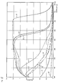
- the numbers of the individual curves correspond to the test numbers above.
- the absorption spectra shown were with a spectrophotometer in the visible range of 350 - 750 nm recorded.
- Example 4 is used to compare the degradation of TOC and AOX at various persulfate concentrations and a dwell time from 80 sec.
- Two bundle heat exchangers each with 25 internal DN 15 pipes (Internal volume of the reactor 4.4 l) were screwed together and set up vertically.
- the lower heat exchanger served as a preheater for the wastewater to be treated (in the coat) and at the same time as a cooler for the treated Sewage (inner pipes).
- the upper heat exchanger was used as a reactor used, with thermal oil as a heat transfer medium for the jacket heating served.
- a tube vessel was placed above the reactor screwed with a volume of approx. 12 l. Halfway there The height of the tube vessel was a 2-rod probe insulated with Teflon led as a conductive point level sensor inside the vessel.
- Reactor pressure 5-6 bar
- Funding volume approx. 200 l / h
- Reactor residence time 80 sec.
- Temperature inlet preheater 23 ° C
- Middle reactor temperature ⁇ 140 ° C
- Temperature after cooling down 54 ° C
- Wastewater from a physical / chemical treatment for oil splitting plants with one TOC value: 2278 mg / l AOX value: 0.9 mg / l inorganic chloride: 0.2 g / l at pH 11.2 was used as an aqueous solution.
- Persulfate used TOC AOX 6 g / l 2102 mg / l 0.8 mg / l 12 g / l 2056 mg / l 0.4 mg / l 24 g / l 1692 mg / l 0.2 mg / l
- the example shows the dependence of the reduction in TOC or AOX values, that is, the breakdown of pollutants from the amount of persulfate used.
- AOX value decreases linearly in the present case the amount of persulfate used.
- AOX and TOC values are at 24 g / l persulphate used with a residence time of only 80 seconds already dropped to very low values.
- Example 5 demonstrates the possibility of keeping the pH constant in the keep alkaline to weakly alkaline range and thereby further increasing the reaction rate.
- the reactor part (upper bundle heat exchanger) through a heatable pipe section replaced and this filled with ceramic sash rings.
- a pH measuring and control device installed with integrated PID controller.
- four diaphragm metering pumps (alkali delivery) controlled via the analog output signal of the PID controller.
- the first pump was connected after the main feed pump, the second pump metered into the reactor head (tube vessel), the third pump metered approx. 30 cm below the top edge of the reactor dosed into the reactor and the fourth pump approx. 60 cm below the top edge of the reactor into the reactor.
- the Setpoint of the wastewater outlet was set to pH 7.5 and the metering pumps are set to the same delivery volume.
- the Pump power increased proportionally to the analog signal.
- the aqueous solution used was waste water, namely landfill leachate TOC value: 301 mg / l AOX value: 4.7 mg / l Nickel: (complex bound) 3.4 mg / l inorganic chloride: 8.7 g / l at a pH of 9.3.
- the persulfate concentration was gradually increased and the Controlled pollutant degradation.
Landscapes
- Chemical & Material Sciences (AREA)
- Engineering & Computer Science (AREA)
- Organic Chemistry (AREA)
- Water Supply & Treatment (AREA)
- Hydrology & Water Resources (AREA)
- Environmental & Geological Engineering (AREA)
- Life Sciences & Earth Sciences (AREA)
- Chemical Kinetics & Catalysis (AREA)
- Health & Medical Sciences (AREA)
- Toxicology (AREA)
- Mechanical Engineering (AREA)
- Treatment Of Water By Oxidation Or Reduction (AREA)
- Processing Of Solid Wastes (AREA)
Applications Claiming Priority (4)
| Application Number | Priority Date | Filing Date | Title |
|---|---|---|---|
| DE19640226 | 1996-09-30 | ||
| DE19640226 | 1996-09-30 | ||
| DE19653426A DE19653426A1 (de) | 1996-09-30 | 1996-12-20 | Verfahren zum Abbau von Schadstoffen |
| DE19653426 | 1996-12-20 |
Publications (2)
| Publication Number | Publication Date |
|---|---|
| EP0832852A2 true EP0832852A2 (fr) | 1998-04-01 |
| EP0832852A3 EP0832852A3 (fr) | 1998-07-29 |
Family
ID=26029951
Family Applications (1)
| Application Number | Title | Priority Date | Filing Date |
|---|---|---|---|
| EP97116376A Withdrawn EP0832852A3 (fr) | 1996-09-30 | 1997-09-19 | Procédé pour la dégradation de matières nuisibles |
Country Status (1)
| Country | Link |
|---|---|
| EP (1) | EP0832852A3 (fr) |
Cited By (11)
| Publication number | Priority date | Publication date | Assignee | Title |
|---|---|---|---|---|
| FR2780902A1 (fr) * | 1998-07-10 | 2000-01-14 | Electrolyse L | Procede de transformation de structures chimiques dans un fluide sous l'action des ultrasons et dispositif pour sa mise en oeuvre |
| EP1008556A3 (fr) * | 1998-12-07 | 2000-07-05 | Preussag AG | Procédé et dispositif pour la décontamination des eaux chargées de polluants |
| WO2006040648A1 (fr) * | 2004-10-15 | 2006-04-20 | Sea Marconi Technologies Di Wander Tumiatti S.A.S. | Processus de deux degradations et/ou de detoxication de polluants chimiques et biologiques |
| US7560033B2 (en) | 2004-10-13 | 2009-07-14 | E.I. Dupont De Nemours And Company | Multi-functional oxidizing composition |
| CN102883783A (zh) * | 2010-04-26 | 2013-01-16 | 三菱瓦斯化学株式会社 | 含有过硫酸盐和银络合物的化学物质降解用处理剂及使用了其的化学物质的降解方法 |
| GB2530482A (en) * | 2014-09-02 | 2016-03-30 | Philip Cheung | Method of removing metal ions from aqueous solutions |
| CN106698770A (zh) * | 2016-12-08 | 2017-05-24 | 中节能工程技术研究院有限公司 | 一种复合催化氧化‑膜分离废水处理集成方法及装置 |
| CN108217909A (zh) * | 2018-03-13 | 2018-06-29 | 长沙紫宸科技开发有限公司 | 一种危险废水亚临界/超临界催化氧化器 |
| CN112939155A (zh) * | 2021-01-29 | 2021-06-11 | 华中科技大学 | 利用活性炭纤维电极电容活化过硫酸盐降解医药废水的方法 |
| CN113979435A (zh) * | 2021-11-17 | 2022-01-28 | 厦门理工学院 | 一种生物炭及其在催化过硫酸钠降解4-氯苯酚上的运用 |
| CN113979530A (zh) * | 2021-11-22 | 2022-01-28 | 湖南大学 | 用于去除水中有机污染物的药剂、方法及应用 |
Family Cites Families (9)
| Publication number | Priority date | Publication date | Assignee | Title |
|---|---|---|---|---|
| FR2192981B1 (fr) * | 1972-07-21 | 1988-11-10 | Air Liquide Fr | |
| US4276198A (en) * | 1979-03-01 | 1981-06-30 | It Enviroscience, Inc. | Destruction method for the wet combustion of organics |
| DE3430484A1 (de) * | 1984-08-18 | 1986-02-27 | Basf Ag, 6700 Ludwigshafen | Verfahren zur oxidativen reinigung von abwaessern |
| CA1276776C (fr) * | 1986-04-03 | 1990-11-27 | Jack Edward Binning | Methode et appareillage pour effectuer des reactions chimiques controlees |
| US5232604A (en) * | 1990-01-31 | 1993-08-03 | Modar, Inc. | Process for the oxidation of materials in water at supercritical temperatures utilizing reaction rate enhancers |
| WO1994018127A1 (fr) * | 1993-02-03 | 1994-08-18 | Kurita Water Industries Ltd. | Procede de production d'eau pure |
| FR2718981B1 (fr) * | 1994-04-26 | 1996-05-31 | Commissariat Energie Atomique | Installation pour le traitement de déchets hétérogènes par oxydation en voie humide mise en Óoeuvre au moyen d'un autoclave. |
| DE4430391A1 (de) * | 1994-08-26 | 1996-02-29 | Eilenburger Elektrolyse & Umwelttechnik Gmbh | Verfahren zum oxidativen Abbau von Schadstoffen in Prozeßlösungen, Abwässern und Trinkwasser sowie Oxidations-, Entgiftungs- und Desodorierungsmittel |
| FR2726261B1 (fr) * | 1994-10-27 | 1997-01-17 | Omnium Traitement Valorisa | Procede et installation de traitement d'effluents par oxydation en presence d'un catalyseur heterogene |
-
1997
- 1997-09-19 EP EP97116376A patent/EP0832852A3/fr not_active Withdrawn
Cited By (16)
| Publication number | Priority date | Publication date | Assignee | Title |
|---|---|---|---|---|
| WO2000002821A1 (fr) * | 1998-07-10 | 2000-01-20 | L'electrolyse | Dispositif de transformation de structures chimiques dans un fluide comprenant un solvant et des sels sous l'action des ultrasons |
| FR2780902A1 (fr) * | 1998-07-10 | 2000-01-14 | Electrolyse L | Procede de transformation de structures chimiques dans un fluide sous l'action des ultrasons et dispositif pour sa mise en oeuvre |
| EP1008556A3 (fr) * | 1998-12-07 | 2000-07-05 | Preussag AG | Procédé et dispositif pour la décontamination des eaux chargées de polluants |
| US7560033B2 (en) | 2004-10-13 | 2009-07-14 | E.I. Dupont De Nemours And Company | Multi-functional oxidizing composition |
| WO2006040648A1 (fr) * | 2004-10-15 | 2006-04-20 | Sea Marconi Technologies Di Wander Tumiatti S.A.S. | Processus de deux degradations et/ou de detoxication de polluants chimiques et biologiques |
| CN102883783A (zh) * | 2010-04-26 | 2013-01-16 | 三菱瓦斯化学株式会社 | 含有过硫酸盐和银络合物的化学物质降解用处理剂及使用了其的化学物质的降解方法 |
| CN102883783B (zh) * | 2010-04-26 | 2016-01-13 | 三菱瓦斯化学株式会社 | 含有过硫酸盐和银络合物的化学物质降解用处理剂及使用了其的化学物质的降解方法 |
| GB2530482B (en) * | 2014-09-02 | 2021-07-21 | Cheung Philip | Method of removing metal ions from aqueous solutions |
| GB2530482A (en) * | 2014-09-02 | 2016-03-30 | Philip Cheung | Method of removing metal ions from aqueous solutions |
| CN106698770A (zh) * | 2016-12-08 | 2017-05-24 | 中节能工程技术研究院有限公司 | 一种复合催化氧化‑膜分离废水处理集成方法及装置 |
| CN108217909A (zh) * | 2018-03-13 | 2018-06-29 | 长沙紫宸科技开发有限公司 | 一种危险废水亚临界/超临界催化氧化器 |
| CN108217909B (zh) * | 2018-03-13 | 2023-10-27 | 长沙紫宸科技开发有限公司 | 一种危险废水亚临界/超临界催化氧化器 |
| CN112939155A (zh) * | 2021-01-29 | 2021-06-11 | 华中科技大学 | 利用活性炭纤维电极电容活化过硫酸盐降解医药废水的方法 |
| CN112939155B (zh) * | 2021-01-29 | 2023-05-16 | 华中科技大学 | 利用活性炭纤维电极电容活化过硫酸盐降解医药废水的方法 |
| CN113979435A (zh) * | 2021-11-17 | 2022-01-28 | 厦门理工学院 | 一种生物炭及其在催化过硫酸钠降解4-氯苯酚上的运用 |
| CN113979530A (zh) * | 2021-11-22 | 2022-01-28 | 湖南大学 | 用于去除水中有机污染物的药剂、方法及应用 |
Also Published As
| Publication number | Publication date |
|---|---|
| EP0832852A3 (fr) | 1998-07-29 |
Similar Documents
| Publication | Publication Date | Title |
|---|---|---|
| DE69310912T2 (de) | Verfahren und vorrichtung zur überwachung von mikroorganismen | |
| EP0478583B2 (fr) | Procede et installation pour le traitement de liquides charges de matieres polluantes | |
| Thanekar et al. | Hybrid treatment strategies based on hydrodynamic cavitation, advanced oxidation processes, and aerobic oxidation for efficient removal of naproxen | |
| Goi et al. | Hydrogen peroxide photolysis, Fenton reagent and photo-Fenton for the degradation of nitrophenols: a comparative study | |
| Shokri | Degradation of 2-nitrophenol from petrochemical wastewater by ozone | |
| Lakshmi et al. | Treatment of acid violet 7 dye containing effluent using the hybrid approach based on hydrodynamic cavitation | |
| DE3022273A1 (de) | Chlordioxid-erzeugungsanlage | |
| DE284754T1 (de) | Verfahren zur behandlung von verunreinigtem material. | |
| EP0832852A2 (fr) | Procédé pour la dégradation de matières nuisibles | |
| Lakshmi et al. | Acoustic and hydrodynamic cavitation-based combined treatment techniques for the treatment of industrial real effluent containing mainly pharmaceutical compounds | |
| EP2794492B1 (fr) | Procédé pour traiter une liqueur résiduaire contenant des sulfures | |
| DE2728554B2 (de) | Verfahren zum Naßoxidieren von Abwässern und/oder flüssigem Abfall | |
| Monteagudo et al. | Advanced oxidation processes for destruction of cyanide from thermoelectric power station waste waters | |
| DE4000369A1 (de) | Verfahren und vorrichtung zur abwasserbehandlung | |
| US5122282A (en) | Method for treating water and/or wastewater | |
| Yang et al. | Iodine-enhanced ultrasound degradation of sulfamethazine in water | |
| DE69123753T2 (de) | Peroxosäureherstellung | |
| Surpăţeanu et al. | Advanced oxidation processes for decolorization of aqueous solution containing Acid Red G azo dye | |
| Momin et al. | Degradation of reactive violet 1 using innovative approach of hydrodynamic cavitation coupled with oxidants | |
| Parıltı et al. | Application of Box–Wilson experimental design method for the solar photocatalytic degradation of textile dyestuff with Fe (III)/H2O2/solar UV process | |
| DE10247686B3 (de) | Reaktor zum Entkalken und gleichzeitigem Entfernen von Schadstoffen | |
| AT392260B (de) | Verfahren zur nassoxidation von schmutzstoffen in abwaessern | |
| US5171441A (en) | Apparatus for treating water and/or wastewater | |
| DE19653426A1 (de) | Verfahren zum Abbau von Schadstoffen | |
| DE3921436A1 (de) | Verfahren zur aufbereitung photochemischer abwaesser |
Legal Events
| Date | Code | Title | Description |
|---|---|---|---|
| PUAI | Public reference made under article 153(3) epc to a published international application that has entered the european phase |
Free format text: ORIGINAL CODE: 0009012 |
|
| AK | Designated contracting states |
Kind code of ref document: A2 Designated state(s): AT BE CH DE DK ES FR GB GR IE IT LI NL PT SE |
|
| AX | Request for extension of the european patent |
Free format text: AL;LT;LV;RO;SI |
|
| PUAL | Search report despatched |
Free format text: ORIGINAL CODE: 0009013 |
|
| AK | Designated contracting states |
Kind code of ref document: A3 Designated state(s): AT BE CH DE DK ES FI FR GB GR IE IT LI LU MC NL PT SE |
|
| AX | Request for extension of the european patent |
Free format text: AL;LT;LV;RO;SI |
|
| AKX | Designation fees paid |
Free format text: AT BE CH DE DK ES FR GB GR IE IT LI NL PT SE |
|
| RBV | Designated contracting states (corrected) |
Designated state(s): AT BE CH DE DK ES FR GB GR IE IT LI NL PT SE |
|
| STAA | Information on the status of an ep patent application or granted ep patent |
Free format text: STATUS: THE APPLICATION IS DEEMED TO BE WITHDRAWN |
|
| 18D | Application deemed to be withdrawn |
Effective date: 19990130 |