EP0832962A2 - Appareil thermique et procédé pour éliminer des matières polluantes de l'huile - Google Patents
Appareil thermique et procédé pour éliminer des matières polluantes de l'huile Download PDFInfo
- Publication number
- EP0832962A2 EP0832962A2 EP97307661A EP97307661A EP0832962A2 EP 0832962 A2 EP0832962 A2 EP 0832962A2 EP 97307661 A EP97307661 A EP 97307661A EP 97307661 A EP97307661 A EP 97307661A EP 0832962 A2 EP0832962 A2 EP 0832962A2
- Authority
- EP
- European Patent Office
- Prior art keywords
- solids
- vessel
- oil
- reaction zone
- recited
- Prior art date
- Legal status (The legal status is an assumption and is not a legal conclusion. Google has not performed a legal analysis and makes no representation as to the accuracy of the status listed.)
- Granted
Links
- 239000000356 contaminant Substances 0.000 title claims abstract description 29
- 238000000034 method Methods 0.000 title claims description 29
- 239000007787 solid Substances 0.000 claims abstract description 106
- 239000000571 coke Substances 0.000 claims abstract description 38
- 229930195733 hydrocarbon Natural products 0.000 claims abstract description 27
- 150000002430 hydrocarbons Chemical class 0.000 claims abstract description 26
- 239000004215 Carbon black (E152) Substances 0.000 claims abstract description 23
- 238000010438 heat treatment Methods 0.000 claims abstract description 19
- 229910052751 metal Inorganic materials 0.000 claims abstract description 12
- 239000002184 metal Substances 0.000 claims abstract description 12
- 238000009833 condensation Methods 0.000 claims abstract description 11
- 230000005494 condensation Effects 0.000 claims abstract description 11
- 150000002739 metals Chemical class 0.000 claims abstract description 11
- 238000006243 chemical reaction Methods 0.000 claims description 31
- XLYOFNOQVPJJNP-UHFFFAOYSA-N water Substances O XLYOFNOQVPJJNP-UHFFFAOYSA-N 0.000 claims description 13
- 229910000831 Steel Inorganic materials 0.000 claims description 5
- 239000000567 combustion gas Substances 0.000 claims description 5
- 239000010959 steel Substances 0.000 claims description 5
- 238000009991 scouring Methods 0.000 claims description 3
- 230000008016 vaporization Effects 0.000 claims description 3
- 238000000151 deposition Methods 0.000 claims 1
- 239000000047 product Substances 0.000 abstract description 15
- 239000010913 used oil Substances 0.000 abstract description 6
- 150000004820 halides Chemical class 0.000 abstract description 4
- 239000006227 byproduct Substances 0.000 abstract description 3
- 239000003921 oil Substances 0.000 description 73
- 239000002699 waste material Substances 0.000 description 11
- 239000007789 gas Substances 0.000 description 6
- 239000008186 active pharmaceutical agent Substances 0.000 description 5
- 239000000919 ceramic Substances 0.000 description 5
- 239000010779 crude oil Substances 0.000 description 3
- 238000000197 pyrolysis Methods 0.000 description 3
- 238000000926 separation method Methods 0.000 description 3
- XEEYBQQBJWHFJM-UHFFFAOYSA-N Iron Chemical compound [Fe] XEEYBQQBJWHFJM-UHFFFAOYSA-N 0.000 description 2
- PXHVJJICTQNCMI-UHFFFAOYSA-N Nickel Chemical compound [Ni] PXHVJJICTQNCMI-UHFFFAOYSA-N 0.000 description 2
- 238000004458 analytical method Methods 0.000 description 2
- 230000015556 catabolic process Effects 0.000 description 2
- 238000006731 degradation reaction Methods 0.000 description 2
- 238000000605 extraction Methods 0.000 description 2
- 239000000446 fuel Substances 0.000 description 2
- 239000012263 liquid product Substances 0.000 description 2
- 239000000463 material Substances 0.000 description 2
- 238000005007 materials handling Methods 0.000 description 2
- 238000011084 recovery Methods 0.000 description 2
- 239000010802 sludge Substances 0.000 description 2
- OYPRJOBELJOOCE-UHFFFAOYSA-N Calcium Chemical compound [Ca] OYPRJOBELJOOCE-UHFFFAOYSA-N 0.000 description 1
- VYZAMTAEIAYCRO-UHFFFAOYSA-N Chromium Chemical compound [Cr] VYZAMTAEIAYCRO-UHFFFAOYSA-N 0.000 description 1
- 235000008733 Citrus aurantifolia Nutrition 0.000 description 1
- RYGMFSIKBFXOCR-UHFFFAOYSA-N Copper Chemical compound [Cu] RYGMFSIKBFXOCR-UHFFFAOYSA-N 0.000 description 1
- DGAQECJNVWCQMB-PUAWFVPOSA-M Ilexoside XXIX Chemical compound C[C@@H]1CC[C@@]2(CC[C@@]3(C(=CC[C@H]4[C@]3(CC[C@@H]5[C@@]4(CC[C@@H](C5(C)C)OS(=O)(=O)[O-])C)C)[C@@H]2[C@]1(C)O)C)C(=O)O[C@H]6[C@@H]([C@H]([C@@H]([C@H](O6)CO)O)O)O.[Na+] DGAQECJNVWCQMB-PUAWFVPOSA-M 0.000 description 1
- FYYHWMGAXLPEAU-UHFFFAOYSA-N Magnesium Chemical compound [Mg] FYYHWMGAXLPEAU-UHFFFAOYSA-N 0.000 description 1
- PWHULOQIROXLJO-UHFFFAOYSA-N Manganese Chemical compound [Mn] PWHULOQIROXLJO-UHFFFAOYSA-N 0.000 description 1
- ZOKXTWBITQBERF-UHFFFAOYSA-N Molybdenum Chemical compound [Mo] ZOKXTWBITQBERF-UHFFFAOYSA-N 0.000 description 1
- OAICVXFJPJFONN-UHFFFAOYSA-N Phosphorus Chemical compound [P] OAICVXFJPJFONN-UHFFFAOYSA-N 0.000 description 1
- ZLMJMSJWJFRBEC-UHFFFAOYSA-N Potassium Chemical compound [K] ZLMJMSJWJFRBEC-UHFFFAOYSA-N 0.000 description 1
- BQCADISMDOOEFD-UHFFFAOYSA-N Silver Chemical compound [Ag] BQCADISMDOOEFD-UHFFFAOYSA-N 0.000 description 1
- 229910000639 Spring steel Inorganic materials 0.000 description 1
- NINIDFKCEFEMDL-UHFFFAOYSA-N Sulfur Chemical compound [S] NINIDFKCEFEMDL-UHFFFAOYSA-N 0.000 description 1
- 235000011941 Tilia x europaea Nutrition 0.000 description 1
- RTAQQCXQSZGOHL-UHFFFAOYSA-N Titanium Chemical compound [Ti] RTAQQCXQSZGOHL-UHFFFAOYSA-N 0.000 description 1
- HCHKCACWOHOZIP-UHFFFAOYSA-N Zinc Chemical compound [Zn] HCHKCACWOHOZIP-UHFFFAOYSA-N 0.000 description 1
- QCWXUUIWCKQGHC-UHFFFAOYSA-N Zirconium Chemical compound [Zr] QCWXUUIWCKQGHC-UHFFFAOYSA-N 0.000 description 1
- 238000009825 accumulation Methods 0.000 description 1
- 229910052782 aluminium Inorganic materials 0.000 description 1
- XAGFODPZIPBFFR-UHFFFAOYSA-N aluminium Chemical compound [Al] XAGFODPZIPBFFR-UHFFFAOYSA-N 0.000 description 1
- 229910052788 barium Inorganic materials 0.000 description 1
- DSAJWYNOEDNPEQ-UHFFFAOYSA-N barium atom Chemical compound [Ba] DSAJWYNOEDNPEQ-UHFFFAOYSA-N 0.000 description 1
- 229910052790 beryllium Inorganic materials 0.000 description 1
- ATBAMAFKBVZNFJ-UHFFFAOYSA-N beryllium atom Chemical compound [Be] ATBAMAFKBVZNFJ-UHFFFAOYSA-N 0.000 description 1
- ZOXJGFHDIHLPTG-IGMARMGPSA-N boron-11 atom Chemical compound [11B] ZOXJGFHDIHLPTG-IGMARMGPSA-N 0.000 description 1
- 229910052793 cadmium Inorganic materials 0.000 description 1
- BDOSMKKIYDKNTQ-UHFFFAOYSA-N cadmium atom Chemical compound [Cd] BDOSMKKIYDKNTQ-UHFFFAOYSA-N 0.000 description 1
- 229910052791 calcium Inorganic materials 0.000 description 1
- 239000011575 calcium Substances 0.000 description 1
- 239000003054 catalyst Substances 0.000 description 1
- 239000004568 cement Substances 0.000 description 1
- 238000001311 chemical methods and process Methods 0.000 description 1
- 229910052804 chromium Inorganic materials 0.000 description 1
- 239000011651 chromium Substances 0.000 description 1
- 229910017052 cobalt Inorganic materials 0.000 description 1
- 239000010941 cobalt Substances 0.000 description 1
- GUTLYIVDDKVIGB-UHFFFAOYSA-N cobalt atom Chemical compound [Co] GUTLYIVDDKVIGB-UHFFFAOYSA-N 0.000 description 1
- 238000002485 combustion reaction Methods 0.000 description 1
- 238000010924 continuous production Methods 0.000 description 1
- 229910052802 copper Inorganic materials 0.000 description 1
- 239000010949 copper Substances 0.000 description 1
- 238000010586 diagram Methods 0.000 description 1
- 238000007599 discharging Methods 0.000 description 1
- 230000002708 enhancing effect Effects 0.000 description 1
- 238000002309 gasification Methods 0.000 description 1
- 230000005484 gravity Effects 0.000 description 1
- 125000001183 hydrocarbyl group Chemical group 0.000 description 1
- 229910052742 iron Inorganic materials 0.000 description 1
- 239000004571 lime Substances 0.000 description 1
- 239000007788 liquid Substances 0.000 description 1
- 239000010687 lubricating oil Substances 0.000 description 1
- 229910052749 magnesium Inorganic materials 0.000 description 1
- 239000011777 magnesium Substances 0.000 description 1
- 229910052748 manganese Inorganic materials 0.000 description 1
- 239000011572 manganese Substances 0.000 description 1
- 238000004519 manufacturing process Methods 0.000 description 1
- 229910052750 molybdenum Inorganic materials 0.000 description 1
- 239000011733 molybdenum Substances 0.000 description 1
- 229910052759 nickel Inorganic materials 0.000 description 1
- 239000011574 phosphorus Substances 0.000 description 1
- 229910052698 phosphorus Inorganic materials 0.000 description 1
- 239000011591 potassium Substances 0.000 description 1
- 229910052700 potassium Inorganic materials 0.000 description 1
- 238000004080 punching Methods 0.000 description 1
- 238000010791 quenching Methods 0.000 description 1
- 238000004064 recycling Methods 0.000 description 1
- 238000010992 reflux Methods 0.000 description 1
- 238000005096 rolling process Methods 0.000 description 1
- 229910052709 silver Inorganic materials 0.000 description 1
- 239000004332 silver Substances 0.000 description 1
- 239000011734 sodium Substances 0.000 description 1
- 229910052708 sodium Inorganic materials 0.000 description 1
- 229910001220 stainless steel Inorganic materials 0.000 description 1
- 239000010935 stainless steel Substances 0.000 description 1
- 229910052712 strontium Inorganic materials 0.000 description 1
- CIOAGBVUUVVLOB-UHFFFAOYSA-N strontium atom Chemical compound [Sr] CIOAGBVUUVVLOB-UHFFFAOYSA-N 0.000 description 1
- 229910052717 sulfur Inorganic materials 0.000 description 1
- 239000011593 sulfur Substances 0.000 description 1
- 238000007669 thermal treatment Methods 0.000 description 1
- 239000010936 titanium Substances 0.000 description 1
- 229910052719 titanium Inorganic materials 0.000 description 1
- 230000007704 transition Effects 0.000 description 1
- 229910052720 vanadium Inorganic materials 0.000 description 1
- LEONUFNNVUYDNQ-UHFFFAOYSA-N vanadium atom Chemical compound [V] LEONUFNNVUYDNQ-UHFFFAOYSA-N 0.000 description 1
- 238000009834 vaporization Methods 0.000 description 1
- 229910052725 zinc Inorganic materials 0.000 description 1
- 239000011701 zinc Substances 0.000 description 1
- 229910052726 zirconium Inorganic materials 0.000 description 1
Images


Classifications
-
- B—PERFORMING OPERATIONS; TRANSPORTING
- B01—PHYSICAL OR CHEMICAL PROCESSES OR APPARATUS IN GENERAL
- B01J—CHEMICAL OR PHYSICAL PROCESSES, e.g. CATALYSIS OR COLLOID CHEMISTRY; THEIR RELEVANT APPARATUS
- B01J19/00—Chemical, physical or physico-chemical processes in general; Their relevant apparatus
- B01J19/28—Moving reactors, e.g. rotary drums
-
- C—CHEMISTRY; METALLURGY
- C10—PETROLEUM, GAS OR COKE INDUSTRIES; TECHNICAL GASES CONTAINING CARBON MONOXIDE; FUELS; LUBRICANTS; PEAT
- C10B—DESTRUCTIVE DISTILLATION OF CARBONACEOUS MATERIALS FOR PRODUCTION OF GAS, COKE, TAR, OR SIMILAR MATERIALS
- C10B1/00—Retorts
- C10B1/10—Rotary retorts
-
- C—CHEMISTRY; METALLURGY
- C10—PETROLEUM, GAS OR COKE INDUSTRIES; TECHNICAL GASES CONTAINING CARBON MONOXIDE; FUELS; LUBRICANTS; PEAT
- C10B—DESTRUCTIVE DISTILLATION OF CARBONACEOUS MATERIALS FOR PRODUCTION OF GAS, COKE, TAR, OR SIMILAR MATERIALS
- C10B47/00—Destructive distillation of solid carbonaceous materials with indirect heating, e.g. by external combustion
- C10B47/28—Other processes
- C10B47/30—Other processes in rotary ovens or retorts
-
- C—CHEMISTRY; METALLURGY
- C10—PETROLEUM, GAS OR COKE INDUSTRIES; TECHNICAL GASES CONTAINING CARBON MONOXIDE; FUELS; LUBRICANTS; PEAT
- C10B—DESTRUCTIVE DISTILLATION OF CARBONACEOUS MATERIALS FOR PRODUCTION OF GAS, COKE, TAR, OR SIMILAR MATERIALS
- C10B55/00—Coking mineral oils, bitumen, tar, and the like or mixtures thereof with solid carbonaceous material
- C10B55/02—Coking mineral oils, bitumen, tar, and the like or mixtures thereof with solid carbonaceous material with solid materials
-
- C—CHEMISTRY; METALLURGY
- C10—PETROLEUM, GAS OR COKE INDUSTRIES; TECHNICAL GASES CONTAINING CARBON MONOXIDE; FUELS; LUBRICANTS; PEAT
- C10G—CRACKING HYDROCARBON OILS; PRODUCTION OF LIQUID HYDROCARBON MIXTURES, e.g. BY DESTRUCTIVE HYDROGENATION, OLIGOMERISATION, POLYMERISATION; RECOVERY OF HYDROCARBON OILS FROM OIL-SHALE, OIL-SAND, OR GASES; REFINING MIXTURES MAINLY CONSISTING OF HYDROCARBONS; REFORMING OF NAPHTHA; MINERAL WAXES
- C10G9/00—Thermal non-catalytic cracking, in the absence of hydrogen, of hydrocarbon oils
- C10G9/28—Thermal non-catalytic cracking, in the absence of hydrogen, of hydrocarbon oils with preheated moving solid material
-
- C—CHEMISTRY; METALLURGY
- C10—PETROLEUM, GAS OR COKE INDUSTRIES; TECHNICAL GASES CONTAINING CARBON MONOXIDE; FUELS; LUBRICANTS; PEAT
- C10M—LUBRICATING COMPOSITIONS; USE OF CHEMICAL SUBSTANCES EITHER ALONE OR AS LUBRICATING INGREDIENTS IN A LUBRICATING COMPOSITION
- C10M175/00—Working-up used lubricants to recover useful products ; Cleaning
- C10M175/0025—Working-up used lubricants to recover useful products ; Cleaning by thermal processes
-
- B—PERFORMING OPERATIONS; TRANSPORTING
- B01—PHYSICAL OR CHEMICAL PROCESSES OR APPARATUS IN GENERAL
- B01J—CHEMICAL OR PHYSICAL PROCESSES, e.g. CATALYSIS OR COLLOID CHEMISTRY; THEIR RELEVANT APPARATUS
- B01J2208/00—Processes carried out in the presence of solid particles; Reactors therefor
- B01J2208/00008—Controlling the process
- B01J2208/00017—Controlling the temperature
- B01J2208/00106—Controlling the temperature by indirect heat exchange
- B01J2208/00168—Controlling the temperature by indirect heat exchange with heat exchange elements outside the bed of solid particles
- B01J2208/00212—Plates; Jackets; Cylinders
-
- B—PERFORMING OPERATIONS; TRANSPORTING
- B01—PHYSICAL OR CHEMICAL PROCESSES OR APPARATUS IN GENERAL
- B01J—CHEMICAL OR PHYSICAL PROCESSES, e.g. CATALYSIS OR COLLOID CHEMISTRY; THEIR RELEVANT APPARATUS
- B01J2208/00—Processes carried out in the presence of solid particles; Reactors therefor
- B01J2208/00008—Controlling the process
- B01J2208/00017—Controlling the temperature
- B01J2208/00106—Controlling the temperature by indirect heat exchange
- B01J2208/00168—Controlling the temperature by indirect heat exchange with heat exchange elements outside the bed of solid particles
- B01J2208/00247—Reflux columns
-
- B—PERFORMING OPERATIONS; TRANSPORTING
- B01—PHYSICAL OR CHEMICAL PROCESSES OR APPARATUS IN GENERAL
- B01J—CHEMICAL OR PHYSICAL PROCESSES, e.g. CATALYSIS OR COLLOID CHEMISTRY; THEIR RELEVANT APPARATUS
- B01J2208/00—Processes carried out in the presence of solid particles; Reactors therefor
- B01J2208/00008—Controlling the process
- B01J2208/00017—Controlling the temperature
- B01J2208/00504—Controlling the temperature by means of a burner
-
- B—PERFORMING OPERATIONS; TRANSPORTING
- B01—PHYSICAL OR CHEMICAL PROCESSES OR APPARATUS IN GENERAL
- B01J—CHEMICAL OR PHYSICAL PROCESSES, e.g. CATALYSIS OR COLLOID CHEMISTRY; THEIR RELEVANT APPARATUS
- B01J2208/00—Processes carried out in the presence of solid particles; Reactors therefor
- B01J2208/00008—Controlling the process
- B01J2208/00017—Controlling the temperature
- B01J2208/00513—Controlling the temperature using inert heat absorbing solids in the bed
-
- B—PERFORMING OPERATIONS; TRANSPORTING
- B01—PHYSICAL OR CHEMICAL PROCESSES OR APPARATUS IN GENERAL
- B01J—CHEMICAL OR PHYSICAL PROCESSES, e.g. CATALYSIS OR COLLOID CHEMISTRY; THEIR RELEVANT APPARATUS
- B01J2208/00—Processes carried out in the presence of solid particles; Reactors therefor
- B01J2208/00008—Controlling the process
- B01J2208/00017—Controlling the temperature
- B01J2208/0053—Controlling multiple zones along the direction of flow, e.g. pre-heating and after-cooling
Definitions
- the invention relates to a process for removing contaminants from used oil by subjecting the oil to vaporization and pyrolysis, whereby coke is formed. The contaminants remain with the coke, which can be separated from the oil.
- the invention further relates to a rotating, indirectly heated retort or reactor in which the process is practised.
- Shurtleff discloses a process wherein an inclined boiler heats the waste oil, vaporizing and driving off lighter hydrocarbons at temperatures of about 650 °F. Heavier hydrocarbons and contaminants, amounting to about 10 % of the original oil, collect as a sludge in the bottom of the boiler. The sludge drains for disposal. The lighter hydrocarbons are condensed as a reclaimed oil product.
- HCS In Taylor's system the HCS are continuously circulated in a material handling loop.
- the HCS is a coarse granular solid which is heated outside the kiln and gives up its heat inside the kiln. Transport of the HCS around the loop involves considerable materials-handling equipment.
- U.S. patent 4,303,477 issued to Schmidt et al., discloses co-currently adding a consumable fine-grained reactive solid to a waste material for binding metal and sulfur contaminants during treatment.
- the reactive solids such as lime having a grain size typically less than 1 mm, and waste are thermally cracked as they progress through a rotating, indirectly fired kiln. The solids make a single pass through the kiln, the reactive solid being consumed in the process.
- the present invention provides a simple apparatus and process for reclaiming oil from used, contaminated oil feed.
- the process comprises feeding used oil through a feed line to a rotating thermal reactor wherein the oil is pyrolysed to produce hydrocarbon vapour and coke.
- the contaminants become associated with the coke.
- the vapour and coked solids are removed from the reactor.
- the vapour is condensed to produce a contaminant-free oil product and the contaminant-rich coked solids are collected for disposal, possibly as feed for a cement kiln.
- the equipment used includes a reactor comprising a rotating vessel housed in a heating chamber, means for feeding used oil into the rotating vessel, and an oil recovery system comprising a vapour extraction pipe, a solids removal cyclone, and vapour condensation equipment.
- the rotating vessel is indirectly heated so that its internal surfaces are sufficiently hot to vaporize and pyrolyse the feed oil.
- the feed oil is introduced into the vessel chamber wherein it vaporizes and pyrolyses, forming hydrocarbon vapour and coke. Metals and other contaminants become associated with the coke.
- a charge of coarse granular solids is provided within the vessel chamber.
- the granular solids scour the vessel's internal surface and comminute the coke into fine solids.
- the fine solids may include solids introduced with the feed oil.
- the vapour is extracted from the vessel chamber through an axial pipe. The fine solids are separated within the vessel chamber from the coarse granular solids for removal from the vessel, preferably using a spiral chute.
- the chute spirals from a screened entrance at the vessel's circumference to a discharge outlet at the vessel's axis.
- the chute's screen excludes coarse solids and collects only the fine solids.
- the fine solids are conveyed out of the vessel for disposal.
- Fine solids may also be elutriated with the vapours. Any fine solids associated with the vapours are separated out.
- the substantially solids-free vapours are then condensed to yield product oil.
- the contaminant-rich fine solids are collected for disposal.
- a reactor 1 is provided for thermally treating used contaminated oil 2.
- the reactor 1 is housed within a heating chamber 3 formed by a housing 3a. Heat is generated in the chamber 3 to heat the reactor 1.
- Feed oil 2, contaminated with metals and one or both of water and solids, is fed to the reactor 1 for the separation of the contaminant from the oil component.
- the feed oil is vaporized and pyrolysed, producing a hydrocarbon vapour stream 4, which may contain steam; coke 5 is formed as a byproduct; metals and solid contaminants become associated with the coke 5; and the coke 5 is separated from the hydrocarbon vapours 4.
- the hydrocarbon vapours 4 leave the chamber 3 and are conveyed to a vapour condensation system 6.
- the hydrocarbon vapour 4 are condensed as a substantially contaminant-free product oil 7, which is suitable to provide refinery feedstock.
- the coke 5 is removed from the reactor chamber 3 and is stockpiled or used as fuel.
- the vapour condensation system 6 comprises a cyclone 10 for stripping fine solids 11, including coke, from the hot reaction zone vapours 4.
- the stripped solids 11 are discharged for disposal.
- the stripped vapour 12 proceeds to a vapour scrubber tower ("scrubber") 13, a quench tower (“quencher”) 14, a heat exchanger 15 and on into an overhead drum 16.
- a vapour scrubber tower (scrubber") 13
- quench tower quencher"
- heat exchanger 15 a heat exchanger 15 and on into an overhead drum 16.
- light oil reflux 17 from the quencher 14 and re-circulated scrubber oil 18 cause a heavy fraction of the hydrocarbon vapour 12 to condense (forming the scrubber oil 18), capturing any solids not removed by the cyclone 10.
- the heavy scrubber oil 18 is recycled to the reactor 1 by co-mingling it with the feed oil 2 before treatment.
- Un-condensed vapour 19 from the scrubber 13 is directed to the quencher tower 14 where light condensed oil 20 from the overhead drum and recycled quencher oil 17 are refluxed for condensation of the majority of the vapour 19.
- the quencher oil 17 is passed through a heat exchanger 21 for preheating the feed oil 2.
- Un-condensed vapour 22 is directed to the overhead drum 16 for the separation of water from the lightest fraction of the condensed oil 20 and from non-condensible off-gases 23.
- An off-gas compressor 24 provides the impetus necessary to draw vapour 4 from the reactor 1. Any separated water is discharged as a water product 25.
- the overhead drum oil 20 and quencher oil 17 are combined to form the product oil 7.
- the reactor 1 comprises a cylindrical vessel 30 having a first end 31 and a second end 32.
- Cylinders 33,34 are structurally connected to the vessel 30 with conical transition sections 35,36 and extend axially from the first and second ends 31,32 respectively.
- the vessel 30 is rotatably supported within the heating chamber 3.
- An annular space 37 is formed between the chamber housing 3a and the vessel 30.
- burner 38 discharges heated combustion gas 39 for circulation through the annular space 37.
- a flue stack 40 at the top of the chamber 3 exhausts spend combustion gases 39.
- the first and second end cylinders 33,34 extend through rotary seals 41 formed in the side walls 42 of the chamber housing 3.
- Riding rings 43 are mounted circumferentially to the cylinders 33,34, positioned outside of the chamber housing side walls 42.
- the riding rings and vessel are supported on rollers 44.
- the inside of the vessel 30 is sealed at its first and second ends 31,32 by first and second panels 45,46 respectively forming a reaction zone 50.
- a vapour pipe 53 extends through axis of the second panel 46.
- the vapour pipe 53 connects the reaction zone 50 and the condensation system 6.
- a feed oil line 51 extends through the second end panel 46. The line 51 distributes and discharges feed oil 2 in the reaction zone 50.
- the vessel 30 contains internal heat transfer enhancing surfaces in the form of radially and inwardly extending rings or fins 54.
- reaction zone 50 is charged with coarse granular solids which are non-ablating and are permanently resident within the vessel 30.
- the coarse granular solids form a bed 55 in the bottom of the vessel chamber 50.
- the chute 56 for fines removal.
- the chute 56 has a circumferentially extending first portion 57 connected to a spiral second portion 58.
- the chute 56 forms a passageway 59 for the transport of fine solids to the vapour pipe 53.
- the chute extends opposite to the direction of rotation, from the first portion 57 to the second portion 58. Thus fine solids enter the first portion 57 of the chute 56 and advance through the second portion 58 as the vessel 30 rotates.
- the chute's first portion 57 lies against the inside circumference of the vessel 30 and extends circumferentially for about 120°.
- the chute's first portion 57 comprises side walls 60 conveniently formed by adjacent fins 54, and a bottom formed by the wall of the vessel 30 at its outer radius.
- the inner radius or top of the first portion 57 is fitted with a screen 61.
- the screens openings 61 are small enough to exclude the coarse granular solids yet permit passage of finer solids.
- the chute's second portion 58 is connected to the end of the first portion 57 and comprises a spiral pipe 62 which spirals inwardly from the vessel's circumference towards the vessel's centerline.
- the spiral pipe 62 rotates through about 180° to direct fine solids into the end of the vapour pipe 53.
- a screw conveyor 63 lies along the bottom of the vapour pipe 53 and extends therethrough to a point outside the heating chamber 3.
- a drive 64 rotates the screw conveyor 63.
- the vessel 30 in operation, is rotated on its axis. Radiant and conductive heat from the burner's combustion gases 39 heat the annulus 37 and the walls of the vessel 30.
- the rotary seals 41 are cooled with a flow of combustion air (not shown).
- Heat is indirectly transferred by conduction through the walls of the vessel 30 to the reaction zone 50. Heat is transferred from the vessel's walls and fins 54 to the granular solids to maintain their temperature at about 800 - 1300 °F, which is sufficiently high so that feed oil is vaporized and pyrolized. Typically, the corresponding range of heating chamber temperatures required is about 1025 - 1450 °F.
- Contaminated oil 2 is fed through line 51 to the vessel 30. If liquid water is fed to the reaction zone 50, it will flash and can upset the sub-atmospheric pressure balance. Preheating the oil 2 via exchanger 21 vaporizes water to steam and aids in conservation of heat. Small amounts of water (say less than about 1 wt. %) present in the feed oil 2 may not require preheating.
- the granular solids form a bed 55 which continuously brings bed's contents into contact with the vessel's walls 30 and fins 54, scouring the contacted surfaces.
- the granular solids absorb heat as they contact the vessel 30.
- the feed oil 2 is directed to contact the reactor vessel cylindrical wall just before it rotates under the bed 55.
- the thermal mass of the vessel 30 provides sufficient heating load to substantially instantaneously vaporize and pyrolyse the oil.
- Hydrocarbon vapour 4 is produced and a solid coke byproduct 5 forms on the surfaces of the cylindrical walls of the vessel 30 and the fins 54.
- Contaminants such as metals and solids, remain substantially associated with the coke.
- the oil is directed to contact the bed 55 which is maintained at pyrolysis temperatures through conductive heat transfer with the wall.
- the bed 55 is required to provide the thermal load to pyrolyse the oil.
- the wall of the vessel 30 is maintained at higher temperature than in the first embodiment as required to maintain sufficient temperature of the granular solids in the bed 55.
- the bed of granular solids scour the vessel walls and fins.
- the contaminant-rich coke and solids which may have been associated with the feed oil, are scoured and thereby comminuted into fine solids which are free of the walls and the coarse granular solids.
- Produced vapour 4 is extracted through the vapour pipe 53.
- the velocity of the vapour exiting the reactor vessel will elutriate some of the fine solids 5.
- the elutriated fine solids 5 exit the vapour pipe 53 and are passed through the cyclone 10 for separation of the solids 5 from the vapour stream 4.
- the vapour stream 4 is passed through the condensation system 6, resulting in a liquid product 7 and a non-condensible off-gas stream 23.
- the liquid product 7 is sufficiently free of contaminants so as to be acceptable as a refinery feedstock.
- the off-gases 23 may be flared or be recycled to fuel the heating chamber burners 38.
- the chute 56 comprised an 8" by 4" rectangular section first portion 57 and a 4" diameter pipe spiral second portion 58.
- the chute encompassed about 330° of rotation.
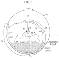
- the vessel was charged with 8500 pounds of inert ceramic balls available under the trade mark Denstone 2000, from Norton Chemical Process Products Corp, Akron, OH. As seen in Figure 3, this produced a deep bed, the chord of which was about 120°.
- the vessel was rotated at 3 to 4 rpm.
- the feed oil was directed to be distributed along the rolling bed.
- Two burners 38 provided about two million BTU/hr for maintaining the heating chamber 3 at about 1380 °F.
- the resulting heat transfer through the vessel wall raised the temperature of the ceramic balls to about 805 °F.
- the product oil was primarily quencher oil (95 to 98 %) with a small contribution (2 to 5 %) from the overhead drum oil.
- Vapour scrubber bottom oil was recycled to the reactor 1 at about 18.5 bbl/day (note that the solids fraction for this test was about 0.5 % and is expected to be higher in other tests).
- the feed oil was directed to impinge directly upon the reactor vessel wall.
- the thermal load to vaporize the oil was provided by the wall itself and not the steel chips.
- the wall did not need to conduct a large amount of heat to the chips through conduction and the wall temperature was correspondingly lower.
- the steel chips successfully scoured coke from the vessel walls, sufficient to prevent blinding of the chute's screen and permit sustainable extraction of fine coke from the reaction zone as it was produced.
Landscapes
- Chemical & Material Sciences (AREA)
- Engineering & Computer Science (AREA)
- Oil, Petroleum & Natural Gas (AREA)
- Organic Chemistry (AREA)
- Chemical Kinetics & Catalysis (AREA)
- General Chemical & Material Sciences (AREA)
- Materials Engineering (AREA)
- Physics & Mathematics (AREA)
- Thermal Sciences (AREA)
- Combustion & Propulsion (AREA)
- Production Of Liquid Hydrocarbon Mixture For Refining Petroleum (AREA)
- Devices And Processes Conducted In The Presence Of Fluids And Solid Particles (AREA)
- Coke Industry (AREA)
- Lubricants (AREA)
- Processing Of Solid Wastes (AREA)
Priority Applications (1)
| Application Number | Priority Date | Filing Date | Title |
|---|---|---|---|
| EP00203474A EP1067171B1 (fr) | 1996-09-27 | 1997-09-29 | Procédé pour éliminer des matières polluantes de l'huile |
Applications Claiming Priority (2)
| Application Number | Priority Date | Filing Date | Title |
|---|---|---|---|
| CA 2186658 CA2186658C (fr) | 1996-09-27 | 1996-09-27 | Procede thermique d'elimination des contaminants contenus dans des produits petroliers |
| CA2186658 | 1996-09-27 |
Related Child Applications (1)
| Application Number | Title | Priority Date | Filing Date |
|---|---|---|---|
| EP00203474A Division EP1067171B1 (fr) | 1996-09-27 | 1997-09-29 | Procédé pour éliminer des matières polluantes de l'huile |
Publications (3)
| Publication Number | Publication Date |
|---|---|
| EP0832962A2 true EP0832962A2 (fr) | 1998-04-01 |
| EP0832962A3 EP0832962A3 (fr) | 1999-06-02 |
| EP0832962B1 EP0832962B1 (fr) | 2005-01-05 |
Family
ID=4158980
Family Applications (2)
| Application Number | Title | Priority Date | Filing Date |
|---|---|---|---|
| EP19970307661 Expired - Lifetime EP0832962B1 (fr) | 1996-09-27 | 1997-09-29 | Appareil thermique et procédé pour éliminer des matières polluantes de l'huile |
| EP00203474A Expired - Lifetime EP1067171B1 (fr) | 1996-09-27 | 1997-09-29 | Procédé pour éliminer des matières polluantes de l'huile |
Family Applications After (1)
| Application Number | Title | Priority Date | Filing Date |
|---|---|---|---|
| EP00203474A Expired - Lifetime EP1067171B1 (fr) | 1996-09-27 | 1997-09-29 | Procédé pour éliminer des matières polluantes de l'huile |
Country Status (4)
| Country | Link |
|---|---|
| EP (2) | EP0832962B1 (fr) |
| JP (2) | JPH10158662A (fr) |
| CA (2) | CA2186658C (fr) |
| DE (2) | DE69732164T2 (fr) |
Cited By (2)
| Publication number | Priority date | Publication date | Assignee | Title |
|---|---|---|---|---|
| WO2004056942A1 (fr) * | 2002-12-19 | 2004-07-08 | Lurgi Lentjes Ag | Procede de distillation a haute temperature en un temps limite d'huile residuelle |
| EP3708637A1 (fr) * | 2019-03-15 | 2020-09-16 | Puraglobe Holding GmbH | Système et procédé de pyrolyse d'huile de fioul lourd |
Families Citing this family (7)
| Publication number | Priority date | Publication date | Assignee | Title |
|---|---|---|---|---|
| US8057662B2 (en) | 2005-05-20 | 2011-11-15 | Value Creation Inc. | Pyrolysis of residual hydrocarbons |
| US7550063B2 (en) | 2005-08-26 | 2009-06-23 | Altene (Canada) Inc. | Method and apparatus for cracking hydrocarbons |
| JP2008169343A (ja) * | 2007-01-15 | 2008-07-24 | Orient Sokki Computer Kk | 油再生方法、油再生装置、脱硫方法、および脱硫装置 |
| HK1212853A2 (zh) * | 2015-08-10 | 2016-06-17 | Shirhao Limited | 回收液体物质的装置和方法 |
| CN115851294B (zh) * | 2022-12-22 | 2023-07-11 | 杭州热星科技有限公司 | 一种含尘热解油气出口防堵自清洁装置 |
| EP4530331A1 (fr) | 2023-09-29 | 2025-04-02 | Puraglobe Holding GmbH | Système et procédé de pyrolyse de mazout lourd |
| WO2025068531A1 (fr) | 2023-09-29 | 2025-04-03 | Puraglobe Holding Gmbh | Système et procédé de pyrolyse de mazout lourd |
Family Cites Families (6)
| Publication number | Priority date | Publication date | Assignee | Title |
|---|---|---|---|---|
| DE699707C (de) * | 1935-12-21 | 1940-12-04 | I G Farbenindustrie Akt Ges | Vorrichtung zum Verschwelen kohlenstoffhaltiger Stoffe |
| EP0028666B1 (fr) * | 1979-11-13 | 1983-04-06 | Alberta Oil Sands Technology And Research Authority | Procédé et appareillage pour le traitement thermique de liquides contenant des hydrocarbures lourds |
| US4473464A (en) * | 1980-05-07 | 1984-09-25 | Conoco Inc. | Method for producing distillable hydrocarbonaceous fuels and carbonaceous agglomerates from a heavy crude oil |
| DE3741623A1 (de) * | 1987-12-04 | 1989-06-15 | Salzgitter Ag | Pyrolyse von bitumen in einem mahlkoerper enthaltenden reaktor |
| US5271808A (en) * | 1988-09-20 | 1993-12-21 | Shurtleff Edward C | Apparatus from waste oil for reclaiming a useful oil product |
| JPH02194097A (ja) * | 1989-01-20 | 1990-07-31 | Masanori Iwase | 揺動撹拌型含油物再生装置 |
-
1996
- 1996-09-27 CA CA 2186658 patent/CA2186658C/fr not_active Expired - Fee Related
- 1996-09-27 CA CA002314586A patent/CA2314586C/fr not_active Expired - Fee Related
-
1997
- 1997-09-29 DE DE69732164T patent/DE69732164T2/de not_active Expired - Lifetime
- 1997-09-29 DE DE69727509T patent/DE69727509T2/de not_active Expired - Lifetime
- 1997-09-29 EP EP19970307661 patent/EP0832962B1/fr not_active Expired - Lifetime
- 1997-09-29 EP EP00203474A patent/EP1067171B1/fr not_active Expired - Lifetime
- 1997-09-29 JP JP30327897A patent/JPH10158662A/ja not_active Withdrawn
-
2000
- 2000-06-29 JP JP2000196161A patent/JP4043169B2/ja not_active Expired - Fee Related
Cited By (6)
| Publication number | Priority date | Publication date | Assignee | Title |
|---|---|---|---|---|
| WO2004056942A1 (fr) * | 2002-12-19 | 2004-07-08 | Lurgi Lentjes Ag | Procede de distillation a haute temperature en un temps limite d'huile residuelle |
| AU2003250003B2 (en) * | 2002-12-19 | 2006-12-21 | Lurgi Lentjes Ag | Method for high-temperature distillation of residual oil in a limited time |
| US7507330B2 (en) | 2002-12-19 | 2009-03-24 | Lurgi Lentjes Ag | Method for high-temperature short-time distillation of residual oil |
| EP3708637A1 (fr) * | 2019-03-15 | 2020-09-16 | Puraglobe Holding GmbH | Système et procédé de pyrolyse d'huile de fioul lourd |
| WO2020187754A1 (fr) * | 2019-03-15 | 2020-09-24 | Puraglobe Holding Gmbh | Système et processus de pyrolyse de mazout lourd |
| US11767475B2 (en) | 2019-03-15 | 2023-09-26 | Puraglobe Holding Gmbh | System and process for heavy fuel oil pyrolysis |
Also Published As
| Publication number | Publication date |
|---|---|
| DE69727509D1 (de) | 2004-03-11 |
| EP1067171A3 (fr) | 2001-02-14 |
| JP2001049265A (ja) | 2001-02-20 |
| EP1067171B1 (fr) | 2004-02-04 |
| CA2186658A1 (fr) | 1998-03-28 |
| JP4043169B2 (ja) | 2008-02-06 |
| CA2314586C (fr) | 2006-11-14 |
| DE69732164T2 (de) | 2005-12-15 |
| DE69732164D1 (de) | 2005-02-10 |
| EP1067171A2 (fr) | 2001-01-10 |
| CA2186658C (fr) | 2001-10-30 |
| EP0832962B1 (fr) | 2005-01-05 |
| EP0832962A3 (fr) | 1999-06-02 |
| JPH10158662A (ja) | 1998-06-16 |
| DE69727509T2 (de) | 2004-12-16 |
| CA2314586A1 (fr) | 1998-03-28 |
Similar Documents
| Publication | Publication Date | Title |
|---|---|---|
| US6589417B2 (en) | Thermal apparatus and process for removing contaminants from oil | |
| US6203765B1 (en) | Thermal apparatus and process for removing contaminants from oil | |
| US4285773A (en) | Apparatus and process for recovery of hydrocarbon from inorganic host materials | |
| US2560767A (en) | Distillation of carbonaceous solids | |
| US4180455A (en) | Process for thermal cracking a heavy hydrocarbon | |
| US10794588B2 (en) | Apparatuses for controlling heat for rapid thermal processing of carbonaceous material and methods for the same | |
| EP3487958B1 (fr) | Système et procédé de pyrolyse | |
| US4160720A (en) | Process and apparatus to produce synthetic crude oil from tar sands | |
| US3703442A (en) | Method for the low-temperature distillation of finely granular bituminous materials which form a pulverulent residue in the process | |
| CA2314586C (fr) | Procede thermique d'elimination des contaminants contenus dans des produits petroliers | |
| US3496094A (en) | Apparatus and method for retorting solids | |
| US4880528A (en) | Method and apparatus for hydrocarbon recovery from tar sands | |
| CN101778927B (zh) | 提炼含油固体的方法和装置 | |
| US4412909A (en) | Process for recovery of oil from shale | |
| US4227990A (en) | Thermal cracking of retort oil | |
| US20090114567A1 (en) | Cracking hydrocarbonaceous materials with heating bodies | |
| US4405438A (en) | Process for recovery of different weight fractions of oil from shale | |
| CN205838921U (zh) | 粉煤快速热解装置 | |
| MXPA00010112A (en) | Thermal apparatus to eliminate ace pollutants | |
| MXPA97007425A (en) | Thermal apparatus to eliminate ace pollutants | |
| US4461674A (en) | Apparatus for recovery of different weight fractions of oil from shale | |
| US4455217A (en) | Retorting process | |
| EA011643B1 (ru) | Способ и устройство для пиролитического облагораживания углеводородного сырья | |
| US4707248A (en) | Process for the retorting of hydrocarbon-containing solids | |
| EP0028666B1 (fr) | Procédé et appareillage pour le traitement thermique de liquides contenant des hydrocarbures lourds |
Legal Events
| Date | Code | Title | Description |
|---|---|---|---|
| PUAI | Public reference made under article 153(3) epc to a published international application that has entered the european phase |
Free format text: ORIGINAL CODE: 0009012 |
|
| AK | Designated contracting states |
Kind code of ref document: A2 Designated state(s): DE FR GB |
|
| AX | Request for extension of the european patent |
Free format text: AL;LT;LV;RO;SI |
|
| PUAL | Search report despatched |
Free format text: ORIGINAL CODE: 0009013 |
|
| AK | Designated contracting states |
Kind code of ref document: A3 Designated state(s): AT BE CH DE DK ES FI FR GB GR IE IT LI LU MC NL PT SE |
|
| AX | Request for extension of the european patent |
Free format text: AL;LT;LV;RO;SI |
|
| 16A | New documents despatched to applicant after publication of the search report |
Effective date: 19990826 |
|
| 17P | Request for examination filed |
Effective date: 19991201 |
|
| AKX | Designation fees paid |
Free format text: DE FR GB |
|
| 17Q | First examination report despatched |
Effective date: 20020318 |
|
| GRAP | Despatch of communication of intention to grant a patent |
Free format text: ORIGINAL CODE: EPIDOSNIGR1 |
|
| GRAS | Grant fee paid |
Free format text: ORIGINAL CODE: EPIDOSNIGR3 |
|
| GRAA | (expected) grant |
Free format text: ORIGINAL CODE: 0009210 |
|
| AK | Designated contracting states |
Kind code of ref document: B1 Designated state(s): DE FR GB |
|
| REG | Reference to a national code |
Ref country code: GB Ref legal event code: FG4D |
|
| REF | Corresponds to: |
Ref document number: 69732164 Country of ref document: DE Date of ref document: 20050210 Kind code of ref document: P |
|
| PLBE | No opposition filed within time limit |
Free format text: ORIGINAL CODE: 0009261 |
|
| STAA | Information on the status of an ep patent application or granted ep patent |
Free format text: STATUS: NO OPPOSITION FILED WITHIN TIME LIMIT |
|
| ET | Fr: translation filed | ||
| 26N | No opposition filed |
Effective date: 20051006 |
|
| REG | Reference to a national code |
Ref country code: GB Ref legal event code: FG4D |
|
| PGFP | Annual fee paid to national office [announced via postgrant information from national office to epo] |
Ref country code: GB Payment date: 20110928 Year of fee payment: 15 |
|
| PGFP | Annual fee paid to national office [announced via postgrant information from national office to epo] |
Ref country code: FR Payment date: 20120926 Year of fee payment: 16 Ref country code: DE Payment date: 20120927 Year of fee payment: 16 |
|
| GBPC | Gb: european patent ceased through non-payment of renewal fee |
Effective date: 20120929 |
|
| PG25 | Lapsed in a contracting state [announced via postgrant information from national office to epo] |
Ref country code: GB Free format text: LAPSE BECAUSE OF NON-PAYMENT OF DUE FEES Effective date: 20120929 |
|
| REG | Reference to a national code |
Ref country code: FR Ref legal event code: ST Effective date: 20140530 |
|
| REG | Reference to a national code |
Ref country code: DE Ref legal event code: R119 Ref document number: 69732164 Country of ref document: DE Effective date: 20140401 |
|
| PG25 | Lapsed in a contracting state [announced via postgrant information from national office to epo] |
Ref country code: FR Free format text: LAPSE BECAUSE OF NON-PAYMENT OF DUE FEES Effective date: 20130930 Ref country code: DE Free format text: LAPSE BECAUSE OF NON-PAYMENT OF DUE FEES Effective date: 20140401 |