EP0833014A2 - Système d'armature pour maçonnerie - Google Patents
Système d'armature pour maçonnerie Download PDFInfo
- Publication number
- EP0833014A2 EP0833014A2 EP97115663A EP97115663A EP0833014A2 EP 0833014 A2 EP0833014 A2 EP 0833014A2 EP 97115663 A EP97115663 A EP 97115663A EP 97115663 A EP97115663 A EP 97115663A EP 0833014 A2 EP0833014 A2 EP 0833014A2
- Authority
- EP
- European Patent Office
- Prior art keywords
- arrangement according
- reinforcement arrangement
- shaped
- plate
- bracket
- Prior art date
- Legal status (The legal status is an assumption and is not a legal conclusion. Google has not performed a legal analysis and makes no representation as to the accuracy of the status listed.)
- Granted
Links
Images







Classifications
-
- E—FIXED CONSTRUCTIONS
- E04—BUILDING
- E04C—STRUCTURAL ELEMENTS; BUILDING MATERIALS
- E04C5/00—Reinforcing elements, e.g. for concrete; Auxiliary elements therefor
- E04C5/01—Reinforcing elements of metal, e.g. with non-structural coatings
-
- E—FIXED CONSTRUCTIONS
- E04—BUILDING
- E04C—STRUCTURAL ELEMENTS; BUILDING MATERIALS
- E04C3/00—Structural elongated elements designed for load-supporting
- E04C3/02—Joists; Girders, trusses, or trusslike structures, e.g. prefabricated; Lintels; Transoms; Braces
-
- E—FIXED CONSTRUCTIONS
- E04—BUILDING
- E04C—STRUCTURAL ELEMENTS; BUILDING MATERIALS
- E04C5/00—Reinforcing elements, e.g. for concrete; Auxiliary elements therefor
- E04C5/01—Reinforcing elements of metal, e.g. with non-structural coatings
- E04C5/02—Reinforcing elements of metal, e.g. with non-structural coatings of low bending resistance, i.e. of essentially one-dimensional [1D] or two-dimensional [2D] extent
-
- E—FIXED CONSTRUCTIONS
- E04—BUILDING
- E04C—STRUCTURAL ELEMENTS; BUILDING MATERIALS
- E04C3/00—Structural elongated elements designed for load-supporting
- E04C3/02—Joists; Girders, trusses, or trusslike structures, e.g. prefabricated; Lintels; Transoms; Braces
- E04C2003/023—Lintels
Definitions
- the invention relates to a reinforcement arrangement for Embedding in masonry, the masonry being a Facing lintel with runner layers and with one underlying runner or roll layer, where furthermore for the production of a bond between printing and / or Traction zones of the facing lintel on pressure bearing stones of the runner layer above the reinforcement arrangement form an anchoring system which the stones placed below the masonry reinforcement the roll layer stops and the mortar partially or completely encompasses, furthermore the reinforcement arrangement a carrier element, which runs horizontally Mortar or cement / mortar bed of a longitudinal joint is embedded above the roll layer and from parallel mutually extending longitudinal bars, a metal band or a mesh fabric, and shaped elements, which in the mortar or cement / mortar bed of vertical joints embedded between stones of the rolling layer or runner layer and up and / or down along the longitudinal bars are arranged below, includes.
- Masonry reinforcements are used for large areas Walls, over window and door openings (as lintel reinforcement), for non-load-bearing partitions on sagging ceilings, in the gable as well as in the mixed masonry. In general, it serves to Setting behavior of masonry wedges to catch. By Vibration and swelling processes can cause tensile or compressive stresses arise which the elasticity of the masonry exceed. As far as not remedy here Expansion joints can or should be created in bed joints (horizontal longitudinal joints) in the mortar bed Steel grid embedded, mostly made of parallel Longitudinal bars with other steel elements connecting them consist.
- runner layer which are bricks, at those in the bricked state the long sides parallel running towards the wall, additionally a rolling layer in front of which the bricks are on the narrow side.
- runner layer which are bricks
- a rolling layer in front of which the bricks are on the narrow side.
- Masonry is subject to tensile and compressive forces which the bricks on their underlying edges be moved apart, being in the one below Rolling layer pressed the top edges of the brick together and pushed the bottom edges apart will. This results in a load-bearing layer directed force to take up over a tensile reinforcement is.
- US-A-2,361,828 is a masonry with a embedded reinforcement known, being used for manufacturing a network between pressure and / or tension zones of the Verblendsturzes the pressure bearing stones of the Runner layer over the reinforcement an anchoring system form that attached below the reinforcement Brings stones of a runner layer to stop.
- the Reinforcement consists of a horizontal one Mortar bed of the longitudinal joint above the runner layer embedded metal band or from at least a longitudinal rod and out on the metal band or Longitudinal bar attached and carried by these, the free ends in the mortar bed of the vertical Grouting the ones below the reinforcement Runner layer are performed. Is the reinforcement?
- a metal band or two or three longitudinal bars then has the connecting the two legs of each bracket Bridge a length equal to the width of the metal band or corresponds to the total width of the longitudinal bars. For this reason, it is necessary to have several bracket sizes to keep in stock for the widths of the used Metal straps or the width of two longitudinal bars have appropriately sized stirrups available, because a lateral bending of the stirrup legs around the Brackets of different widths of the metal band or to be able to adjust the distance between two longitudinal bars not possible, because of the length of the bar bridge for the Metal strips required widths are specified.
- the in the mortar bed vertical joints extending the runner layer Leg of the bracket no firm hold in the mortar bed guaranteed, because in the area e.g. a window opening lying runner layer, the lintel lintel forms, is subject to tensile forces and the hardened Mortar bed itself no additional anchoring for the temple forms.
- EP-A-0 340 840 describes an armoring system for a wall of masonry with one in it Mortar bed to use horizontal alarm, where vertical reinforcement elements are provided which in vertical depressions or openings in the Bricks are introduced, the height or the Length of the vertical reinforcements approximately the height of at least two superimposed bricks corresponds.
- the vertical reinforcements in at least one vertical direction on the horizontal reinforcement arranged and firmly connected to this.
- the known reinforcement device cannot be used as masonry reinforcement with structural load-bearing Effect in the lintel area for facing falls and with the Reinforcement connectable or suspended, open at the top Wire brackets for the production of statically self-supporting Systems, such as facing lintels.
- This task is carried out by a reinforcement arrangement of the o.g. Kind with the features characterized in claim 1 solved.
- the particular advantage of this reinforcement lies in that the tensile and compressive forces occurring are more uniform be led into the masonry, in particular the veneer lintels (or the Grenadiers) prevented from masonry.
- Longitudinal bars as a carrier element can also be a metal band or a mesh for the manufacture of the reinforcement system be used.
- plastic hangers or plates especially one, high inherent rigidity having plastic that still has a certain resilient Has elasticity, which causes the clamps to become jammed and plates in the support element simplified and improved becomes.
- the shaped elements are in an adjacent, Mortar or cement / mortar joint lying parallel to the longitudinal joint led and the plates with a profile and / or raised means. This will next to a firm bond a good hold of the mortar scored in the joints.
- each plate end is preferably on one of the Longitudinal bars end.
- the plates are essentially U- or arcuate, making them excellent for Vertical joints in runner layers as well as in Rolling layers can be used and the largest possible Composite surface between the steel reinforcement elements and create the mortar.
- the plates can be releasably clamped to the longitudinal bars, there is the further advantage that the plates in any distance from each other and at any desired Place can be arranged.
- the plates in any distance from each other and at any desired Place can be arranged.
- the actually occurring compressive and tensile forces or voltage is adjusted.
- the plate ends are hook-shaped, preferably such that the curvature of the hook-shaped end on the longitudinal rod diameter is coordinated. This ensures that the plates are easily hung at predetermined locations can be.
- Another improvement in terms the relative stabilization of the plates to the longitudinal bars results when the panels are under a pretension is clamped on the longitudinal bars and / or the hook-shaped ends of the plates on the Longitudinal bars can be clamped by a snap lock.
- the pinching the plate ends in the longitudinal bars is still supported by the fact that the engagement elements on the Sheets are resilient, i.e. from a suitable Plastic, are formed, but also a elastic steel can be used. Also by bending the engagement elements around the longitudinal bars or is attached to a metal band Plates reached.
- a different length of the plates creates the Possibility that for example up and down plates of different lengths can be used.
- a plate reaching into the rotor layer can also if necessary be longer, the one from the rotor layer protruding plate section simply bent or is flipped.
- the base is the U-shaped plate shorter than the distance of the parallel lying longitudinal bars.
- At least part of the bracket preferably extends or the plate up to the neighboring, parallel Mortar or cement / mortar joint lying along the longitudinal joint. This means a length of the plate, the corresponds to the height of a stone plus the joint width.
- the longitudinal bars are made of better anchoring ribbed steel bars or plastic bars, where this after a further embodiment of the invention are connected by cross bars.
- the cross bars can preferably be at an equidistant distance be arranged from each other.
- a particularly simple and effective arrangement results from the fact that the plate-shaped body has a profile on one end, on the slotted strip is attachable.
- the plate-shaped body one end has retaining tongues, which preferably can be suspended on the cross bars or longitudinal bars.
- the arrangement of the reinforcement arrangement is thereby in advantageously supports that the plate-shaped Body has a support plate at one end.
- the plates can also be made of flat steel, a flat plastic profile or a spiral twisted profile or round steel.
- longitudinal and / or transverse bars are preferred for the longitudinal and / or transverse bars ribbed or smooth steel rods or plastic rods used.
- longitudinal and / or Cross bars made of flat steel or a flat plastic profile consist.
- bracket has two vertical legs and one has horizontal cross piece, with upper temple ends one vertical leg each with one end of the horizontal Connect the crosspiece so that between the upper temple ends and the horizontal cross piece slot-like opening for the carrier elements is.
- the upper temple ends are expediently loop-shaped formed, one end of the loop with a End of the horizontal cross piece and that accordingly other end is connected to a vertical leg.
- upper temple ends are preferably upper temple ends with respect to vertical leg bent at right angles.
- the upper temple ends each other facing or facing and forming between an opening.
- the upper temple ends run preferably parallel to the horizontal crosspiece.
- the Bracket formed in one piece.
- the bracket is a horizontal cross piece and two on one Long side of the horizontal cross piece arranged vertical Thighs and at each short end of the horizontal Cross piece each a bendable tab. This results in a stable, easy-to-assemble bracket.
- the bracket is for inexpensive mass production preferably in one piece from a flat structure, in particular from a sheet metal part, punched out pi-shaped, the crosspiece being bent at right angles to the legs is.
- the vertical legs are expediently planar trained and there are preferred in these Punchings and / or bendable tongues are formed, which, for example, a defined spacing of the stirrup legs of stones of the masonry.
- the stirrups are expediently made of rods, flat steel, a woven fabric, twisted rods or ribbed rods and / or the support elements made of spirally twisted Rods made.
- Fig. 2 which consists in a finished component trained lintel 200 installable reinforcement assembly 100 from a support member 90 from parallel longitudinal bars 10 and 11, which is arranged here at equidistant distance a Cross bars 12 can be connected.
- the longitudinal bars 10 and 11 have a diameter d of, for example, 4 mm.
- This diameter corresponds to the diameter of the plate-shaped Body 113 and the cross bars 12 so that one and the same source material can be accessed can.
- the diameters can also vary be chosen large.
- the plates 113 lie perpendicular to that through the longitudinal and transverse bars 10 to 12 certain level and have different heights h, depending on whether it is for the grenadiers, i.e. For the rolling layer, or for the runner layer of the facing lintel 200 used as an independent component should be (Fig.1).
- the distance between the longitudinal bars b also determines the distance between the free ends of the essentially U-shaped profile, the plate ends 114 are hook-shaped so that they can be pushed over the longitudinal bars or there can be snapped into place. Possibly. can the plates are still under tension.
- the plate ends 114 grip each other opposite inner sides of the longitudinal bars 10, 11 on.
- the from the longitudinal bars 10, 11 and the plates 113 existing reinforcement arrangement 100 does not need to be grid-shaped. It can also be two Single bars are used in the support area of the facing lintel kinked in the side masonry and are anchored.
- the longitudinal bars 10, 11 can also be a metal band, a perforated band or a mesh are used, the as support elements 90 parts used also consist of plastic can.
- Fig. 1 shows typical facing lintels with runners 15 and grenadiers 16.
- the pair of longitudinal bars 10, 11 is embedded in a mortar layer 17 which between the Grenadiers 16 and the runners lying above them 15 lies.
- the longer plates 113 projecting downward or bracket 13 while in the vertical joints between plates 113 standing upward on each rotor stone or bracket 13 protrude, with other length dimensions can be made.
- the towering Brackets 13 or plates 113 extend into the nearest mortar layer 18 between two runners, where they are attached to a lintel membrane from a film 20 adjoin the one end portion in the mortar the joint 18 is embedded between two runner layers and by means of a connection profiling connected to the mortar of the joint 18 by anchoring is.
- the bracket 13 is hook-shaped at its ends 114 formed and with engagement elements 113a, 113b.
- bracket 13 or plates 113 on the support element 90 or on the longitudinal bars 10, 11 there is no bond to predetermined joints.
- the butt joints of the stones can be arranged as desired be because the bracket can be aligned to the position of the butt joints are.
- the top are open, made of a resilient-elastic Steel or plastic material, is a hanging of the Bracket 13 in the support member 90 or in the longitudinal bars 10, 11 effortlessly: the legs of the temple will be either bent outwards, the bracket 13 to the longitudinal bars 10, 11 attached and the pressure on the stirrup legs canceled so that the latter spring back and the bracket is held on the longitudinal bars by means of a clamp fit or the stirrup legs are pressed against each other, the bracket 13 for contact with the longitudinal bars 10, 11 brought and the pressure released, so that the stirrup legs spring back and the bracket 13 to the Longitudinal bars 10, 11 is held clamped.
- the actuation the stirrup leg in one direction or the other depends on whether the bracket with your Legs from the outside or from the inside to the longitudinal bars 10, 11 are clamped, being in use from e.g. Perforated or fabric tapes with the brackets their legs from the outside to the longitudinal edges of the support element 90 are clamped.
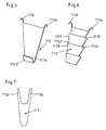
- bracket 13 To prevent the mortar from slipping in one Joint between two stones serves the bracket 13 or is according to a further embodiment according to FIG full-surface, plate-shaped body 113 on his, the Engagement elements 113a, 113b facing end portion 113c provided with an angled portion 113d. Furthermore, the plate-shaped body 113 6 with a sawtooth-like profile 113f be provided on its outer longitudinal edges 113e, 113e '.
- legs 113g, 113g ' can be bent at any point and thus achieve a height-adjustable plate. Furthermore, as shown in FIGS. 4B and 4C, are laterally bendable tongues 118 provided as a pinning of the stones hanging below. In addition the legs 113g, 113g 'can be bent by 90 degrees be so that they are bent sideways and for the plate offers a mortar bond.
- FIG 3 is another embodiment of a Plate 113 shown, which is designed such that these are suspended on the crosspiece 12 of the support element 90 can be.
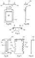
- FIG. 8A and 8B show another according to the invention Design of the plate 113.
- This has a frame-like Recess 130 and a profile 130a on one neck retracted end 132.
- a slotted one Strip 134 can be put on, the holding tabs on the side 136 for hanging in longitudinal rods 10, 11.
- a a further embodiment of the holding tongues 136 is shown in FIG. 9 shown.
- FIG. 10 shows another embodiment of a plate 113.
- this plate 113 a support plate 140 with holding tongues 135.
- a further advantageous modification according to FIG. 11 have the longitudinal edges 113e, 113e 'a tooth-like Profiling 113f. This provides the plate 113 an even better hold for mortar.
- Fig. 12 shows the Plate 113 of Fig. 11 in side view and clarified the arrangement of the support plate 140, which is in the extends substantially at right angles from the plate 113.
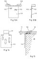
- FIGS. 13A and 13B show an embodiment of the plate 113 with a wide clamp or clip 138. Furthermore, laterally protruding or raised means 122 arranged.
- FIG. 14 also illustrates plate 113 with a Tab 124, which either over the crossbar 13th engages or is pressed onto it.
- 15 represents an installation situation of the plate 13 of FIG. 14.
- a plate 113 lies against a stone 26 and supports it with a support plate 140 on the stone 26.
- the Tab 124 engages over the crossbar 12 of the support element 90.
- FIG. 16 shows a in a perspective view further embodiment of a plate 113.
- a plate 113 Longitudinal edges 113e, 113e 'laterally edged and on one end 132 bent so that it is in retaining tongues 136 pass over on the longitudinal rods 10, 11 lie on.
- This plate 113 has an easy to manufacture Shape that is special due to the bevel is dimensionally stable or rigid.
- the bracket 200 shown in FIG. 17 comprises two vertical ones Legs 210 and 212 and a horizontal Cross piece 214.
- the horizontal cross piece 214 is on both sides via a loop-like structure 216 in each case and 218 connected to legs 210 and 212, respectively.
- the loop-like structures form two overlapping sections 216 and 218 between themselves and the horizontal Cross piece 214 a slot-like opening 220 train, which has an opening between the loops 216 and 218 is accessible or open.
- the loop-like sections 216, 218 of the Brackets 200 can, however, also deviate from FIG. 17 Have an embodiment, namely an embodiment like this as shown in Fig. 17A.
- This configuration go the upper ends of the legs 210, 212 into an approximately ring-shaped section 216 ', 218 ', which are connected via the crossbar 214, wherein the annular sections 216 ', 218' thus angled outwards are that when installing this bracket 200 this annular sections on the head of each adjacent Support the stone.
- the ring-shaped ones Sections 216 ', 218' are formed so that the longitudinal bars 10, 11 of the support element 90 can be passed.
- the loops overlap horizontally during assembly extending longitudinal bars 90 of the reinforcement.
- the longitudinal bars 90 are between web 214 and the overarching Loops 216 and 218 of bracket 200 in opening 220 held clamped.
- clamped on the bracket 200 i.e. held by means of a press fit.
- it is the distance between the two longitudinal bars 90 is fixed.
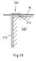
- the web or the horizontal cross piece 214 comes here to lie below the longitudinal bars, as is particularly the case 19 shows where the bracket 200 on a stone 226th abuts and the rods 90 from the stone through the web 214 are spaced.
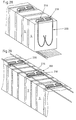
- FIG. 26 shows the bracket 200 designed according to FIG. 17 installation on the head K of a stone S of a grenadier layer, the loop-like sections Support 216, 218 on the head of the stone and so the Bracket 200 is held.
- the rod guide and bend to this loop formation is such that from the rod sections 216a, 216b is approximately horizontal Area F1 and one of the rod sections 216a, 216c horizontal surface F2 is formed.
- the loop-shaped Section 218 corresponds to the loop-shaped section 216, 218 are interconnected and form the crossbar 214 (Figs. 17 and 26).
- connection and mounting of the bracket 200 takes place Longitudinal rods 10, 11 of the support member 90, through the loop-like sections 216, 218 of the bracket 200 therethrough pushed or pulled.
- These longitudinal bars 10, 11 which in the form of wire rods of e.g. 50 m roll 450 of an appropriate wire and cut to length are used (Fig. 27).
- bracket 200 overlaps in the mortar bed and is therefore particularly good Claw properties. It is also possible insert a bracket which is formed under closed is and is encountered on the support surface.
- the temple design can also be such that one later installed support rod not from the inside out inserted, but from the outside in. The advantage is there in that the bracket is prefabricated so that it does not more bent around the support rod or rods must be and not made of round steel or flat steel must be made.
- the two legs 210 and 212 of the bracket 200 can, as shown in Fig. 17, parallel at right angles to that Cross bar 214.
- the angular position can also be larger or smaller, so that the legs 210, 212 to the outside bent obliquely or obliquely to each other are inside.
- flat steel can also be used can.
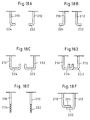
- the free ends of the stirrup legs can also turned towards each other, whereby the bent end portions overlap each other (Fig. 18D).
- the free ends of the stirrup legs can also be used these themselves spiral, i.e. corkscrew-shaped be (Fig. 18E).
- the free ends of the stirrup legs 210, 212 can also be bent in accordance with FIG. 8 F, the bent sections then lying one above the other.
- FIG. 20 Another embodiment of a bracket 300 is shown in FIG. 20 shown.
- This includes a crossbar 310, on the Longitudinal side 312 two legs 314 and 316 arranged are. There is one bendable on the short sides of the web 310 Tab 318 and 320 provided.
- the legs 314 and 316 preferably have cutouts 326 and bendable Tongues 328, which are very well anchored in the Add grout.
- bracket 300 is assembled one indicated for dash 320 with broken lines Bend the position in the direction of the arrow Y and grasp it so the longitudinal bars 90 of the reinforcement.
- the web 310 is cranked, so that the longitudinal bars to a predetermined distance have a stone 330.
- the pre-cut and bent Tongues 328 provide a predetermined distance between Leg 216 and stone 330 in that when inserting of mortar (grout) this also between stirrup legs 214, 216 and stone 330 is introduced or incorporated can.
- the tongues not supported on stone 330 328 also act like barbs and give the bracket 200 an additional hold in the joint bed.
- Lower bends 322, 324 are for engagement of the bracket 300 in hollow chambers 332 of a brick 330. These are preferably perforated blocks 330, in which the It is possible that the large number of holes / perforations the angled sections 322 and 324 can absorb, whereby a firm hold is achieved.
- the bent end portions 322 and 324 can also into horizontal joint sections between two stones 330 intervene.
- Figure 22 shows an advantageous and inexpensive way the manufacture of hangers 300 in mass production.
- 334 pi-shaped pieces are made from a sheet punched out, one transverse side the web 310 and two Longitudinal extensions form the legs 314 and 316.
- the Web 310 bent perpendicular to the legs 314 and 316.
- the protrusions on the short side 310 next to the legs 314 and 316 form the bendable tabs 318 and 320.
- the longitudinal bars 90 of the reinforcement can, for example from a spirally twisted metal rod or Be made of plastic.
- FIG. 23 shows a reinforcement arrangement embedded in a masonry M. from a support element 90 e.g. in shape of two horizontally laid reinforcement bars 10, 11 in the upward and downward bow 13, preferably from flat steel, are hung, however an additional pinning of the stones of the rolling layer or grenadier layer 16 by means of longitudinal bars 410, 411 is provided.
- the longitudinal rods 410, 411 of the pinning are held by the brackets 13 held on the support element 90 encompassed the mortar of the vertical joint reach between two stones.
- bracket 13 or plates 113 in the upper areas with wide cross brackets or clips 138, 218, 318 and 320 are provided (Fig. 13A, 17 and 20) are used when installing the reinforcement arrangement the individual rods 10, 11 of the support member 90 after insertion the bracket or plates inserted. Hook-shaped temples can also be anchored in the mortar Mortar must be placed. Plate-shaped bracket 113 preferably have large openings, so that the grout runs through well during processing can.
- Fig. 24 shows an embodiment of a bracket 13 with in upper area with outward bent overlapping clamps 138 'are provided for holding the bracket 13 during mounting on the already installed stone S one on the side discharge bearing device 420 in the form of a U-shaped Has bracket 421, the web 421a the distance for the two stirrup legs 13a, 13b (Fig. 1) and whose legs 421b, 421c at the upper ends of the stirrup legs 13a, 13b are welded or releasably attached.
- bracket 13 without Claws 420 i.e.
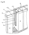
- bracket legs 13a, 13b hook-shaped out of the plane bent out, which is formed by the bracket 13.
- This hook-shaped sections 430, 431 are bent so that these hook-shaped sections 430, 431 on the Support head K of stone S of the facing lintel and in the position of the bracket 13 shown in FIG. 25 is held.
Landscapes
- Engineering & Computer Science (AREA)
- Architecture (AREA)
- Civil Engineering (AREA)
- Structural Engineering (AREA)
- Pit Excavations, Shoring, Fill Or Stabilisation Of Slopes (AREA)
- Road Paving Structures (AREA)
- Reinforcement Elements For Buildings (AREA)
- Manufacturing Of Tubular Articles Or Embedded Moulded Articles (AREA)
Applications Claiming Priority (6)
| Application Number | Priority Date | Filing Date | Title |
|---|---|---|---|
| DE29616856U DE29616856U1 (de) | 1996-09-27 | 1996-09-27 | Bewehrungsanordnung für ein Mauerwerk |
| DE29616856U | 1996-09-27 | ||
| DE29704308U DE29704308U1 (de) | 1996-09-27 | 1997-03-10 | Bewehrungsanordnung für ein Mauerwerk |
| DE29704308U | 1997-03-10 | ||
| DE29714888U | 1997-08-20 | ||
| DE29714888U DE29714888U1 (de) | 1996-09-27 | 1997-08-20 | Bewehrung für ein Mauerwerk |
Publications (3)
| Publication Number | Publication Date |
|---|---|
| EP0833014A2 true EP0833014A2 (fr) | 1998-04-01 |
| EP0833014A3 EP0833014A3 (fr) | 1999-08-18 |
| EP0833014B1 EP0833014B1 (fr) | 2004-06-09 |
Family
ID=27219848
Family Applications (1)
| Application Number | Title | Priority Date | Filing Date |
|---|---|---|---|
| EP19970115663 Expired - Lifetime EP0833014B1 (fr) | 1996-09-27 | 1997-09-10 | Système d'armature pour maçonnerie |
Country Status (1)
| Country | Link |
|---|---|
| EP (1) | EP0833014B1 (fr) |
Cited By (4)
| Publication number | Priority date | Publication date | Assignee | Title |
|---|---|---|---|---|
| EP2053173A1 (fr) * | 2004-03-28 | 2009-04-29 | Stekox GmbH | Support pour joints d'étanchéité |
| GB2460674A (en) * | 2008-06-04 | 2009-12-09 | Wembley Innovation Ltd | Masonry bracket |
| US9988809B2 (en) | 2016-10-06 | 2018-06-05 | Technologie 2000 Inc. | Construction block anchoring system |
| US10202755B2 (en) | 2016-10-06 | 2019-02-12 | Technologie 2000 Inc. | Construction block anchoring system |
Family Cites Families (7)
| Publication number | Priority date | Publication date | Assignee | Title |
|---|---|---|---|---|
| EP0603517B1 (fr) * | 1992-12-24 | 1997-07-30 | Elmenhorst & Co. GmbH | Maçonnerie pour linteau avec armature et dispositif de suspension relatif |
| DE9306276U1 (de) * | 1993-04-26 | 1993-06-17 | Elmenhorst & Co GmbH, 2000 Schenefeld | Mauerwerkabfangvorrichtung |
| DE9217654U1 (de) * | 1992-12-24 | 1993-02-18 | Elmenhorst & Co GmbH, 2000 Schenefeld | Verblendsturz mit Bewehrung |
| DE9400252U1 (de) * | 1993-01-12 | 1994-03-24 | Elmenhorst & Co GmbH, 22869 Schenefeld | Verblendsturz mit Bewehrung |
| DE4438437C2 (de) * | 1994-10-28 | 2002-01-03 | Modersohn Gmbh & Co Kg Wilh | Vorrichtung und Verfahren zur Bewehrung von Mauerwerk über Fensteröffnungen |
| DE29518134U1 (de) * | 1995-11-15 | 1996-01-04 | Elmenhorst & Co GmbH, 22869 Schenefeld | Mauerwerksbewehrung |
| DE29618030U1 (de) * | 1996-10-17 | 1996-11-28 | Halfen GmbH & Co. KG, 40764 Langenfeld | Bewehrungsbügel für ein Verblend-Mauerwerk |
-
1997
- 1997-09-10 EP EP19970115663 patent/EP0833014B1/fr not_active Expired - Lifetime
Cited By (5)
| Publication number | Priority date | Publication date | Assignee | Title |
|---|---|---|---|---|
| EP2053173A1 (fr) * | 2004-03-28 | 2009-04-29 | Stekox GmbH | Support pour joints d'étanchéité |
| GB2460674A (en) * | 2008-06-04 | 2009-12-09 | Wembley Innovation Ltd | Masonry bracket |
| AU2009254997B2 (en) * | 2008-06-04 | 2014-03-27 | Wembley Innovation Ltd. | Masonry bracket, system and construction method |
| US9988809B2 (en) | 2016-10-06 | 2018-06-05 | Technologie 2000 Inc. | Construction block anchoring system |
| US10202755B2 (en) | 2016-10-06 | 2019-02-12 | Technologie 2000 Inc. | Construction block anchoring system |
Also Published As
| Publication number | Publication date |
|---|---|
| EP0833014A3 (fr) | 1999-08-18 |
| EP0833014B1 (fr) | 2004-06-09 |
Similar Documents
| Publication | Publication Date | Title |
|---|---|---|
| DE3606112C2 (de) | Tragschiene für Unterdecken | |
| EP0258338A1 (fr) | Pieces de fixation pour structures coffrees en beton | |
| EP2963205B1 (fr) | Dispositif de coffrage | |
| DE102018121776A1 (de) | Zarge für Fenster und Türen sowie Fenster- oder Türelement mit einer solchen | |
| DE10147831B4 (de) | Ständerwand | |
| CH683545A5 (de) | Schubbewehrung für Flachdecken. | |
| EP0117443B1 (fr) | Coffrage permanent et calorifuge pour constructions de murs | |
| EP1589156B1 (fr) | Connecteur pour éléments préfabriqués en béton | |
| EP0833014A2 (fr) | Système d'armature pour maçonnerie | |
| DE19737515C2 (de) | Vorrichtung zur Befestigung von Bauteilen an und im Abstand zu einem Tragwerk, insbesondere von Längsprofilen an und im Abstand zu einer Bauwerkswand und dafür geeigneter Abstandhalter | |
| EP0737786B1 (fr) | Linteau en maçonnerie avec élément support | |
| EP0541958B1 (fr) | Système de fixation de plaques de plafond | |
| DE102006052648B4 (de) | Traganker zur Befestigung von Fassadenelementen an einer Gebäudewand, Gebäudewandkonstruktion sowie Verwendung eines Tragankers | |
| EP0773333B1 (fr) | Armature pour maçonnerie | |
| EP1327732B1 (fr) | Coffrage de rive pour dalles en béton | |
| DE2950614C2 (de) | Profilträger aus Blech für Trägerdecken aus Stahlbeton und Hohlkörpersteinen | |
| DE29518134U1 (de) | Mauerwerksbewehrung | |
| DE29714888U1 (de) | Bewehrung für ein Mauerwerk | |
| DE29704308U1 (de) | Bewehrungsanordnung für ein Mauerwerk | |
| DE9400252U1 (de) | Verblendsturz mit Bewehrung | |
| DE4211823C2 (de) | Profilabhänger und Befestigungssystem zum Anbringen von Abdeckplatten | |
| DE202005018617U1 (de) | Abschalkorb und Abschalvorrichtung | |
| CH672523A5 (fr) | ||
| EP4063589B1 (fr) | Élément de coffrage pour une construction en béton, procede de production un tel coffrage et un procede de coffrage | |
| DE102004026429B3 (de) | Fugenbandhalterung sowie Herstellungsverfahren für Betonierungsabschnitte |
Legal Events
| Date | Code | Title | Description |
|---|---|---|---|
| PUAI | Public reference made under article 153(3) epc to a published international application that has entered the european phase |
Free format text: ORIGINAL CODE: 0009012 |
|
| AK | Designated contracting states |
Kind code of ref document: A2 Designated state(s): DE |
|
| AX | Request for extension of the european patent |
Free format text: AL;LT;LV;RO;SI |
|
| PUAL | Search report despatched |
Free format text: ORIGINAL CODE: 0009013 |
|
| AK | Designated contracting states |
Kind code of ref document: A3 Designated state(s): AT BE CH DE DK ES FI FR GB GR IE IT LI LU MC NL PT SE |
|
| AX | Request for extension of the european patent |
Free format text: AL;LT;LV;RO;SI |
|
| 17P | Request for examination filed |
Effective date: 19990806 |
|
| AKX | Designation fees paid |
Free format text: DE |
|
| RAP1 | Party data changed (applicant data changed or rights of an application transferred) |
Owner name: ELMENHORST BAUSPEZIALARTIKEL GMBH & CO.KG |
|
| 17Q | First examination report despatched |
Effective date: 20020614 |
|
| GRAP | Despatch of communication of intention to grant a patent |
Free format text: ORIGINAL CODE: EPIDOSNIGR1 |
|
| GRAS | Grant fee paid |
Free format text: ORIGINAL CODE: EPIDOSNIGR3 |
|
| GRAA | (expected) grant |
Free format text: ORIGINAL CODE: 0009210 |
|
| AK | Designated contracting states |
Kind code of ref document: B1 Designated state(s): DE |
|
| REF | Corresponds to: |
Ref document number: 59711698 Country of ref document: DE Date of ref document: 20040715 Kind code of ref document: P |
|
| PLBE | No opposition filed within time limit |
Free format text: ORIGINAL CODE: 0009261 |
|
| STAA | Information on the status of an ep patent application or granted ep patent |
Free format text: STATUS: NO OPPOSITION FILED WITHIN TIME LIMIT |
|
| 26N | No opposition filed |
Effective date: 20050310 |
|
| PGFP | Annual fee paid to national office [announced via postgrant information from national office to epo] |
Ref country code: DE Payment date: 20161118 Year of fee payment: 20 |
|
| REG | Reference to a national code |
Ref country code: DE Ref legal event code: R071 Ref document number: 59711698 Country of ref document: DE |