EP0833020A1 - Vorrichtung zum Ausbilden einer definierten Fuge als Sollbruchstelle zwischen zwei Estrichplatten und Verwendung der Vorrichtung - Google Patents
Vorrichtung zum Ausbilden einer definierten Fuge als Sollbruchstelle zwischen zwei Estrichplatten und Verwendung der Vorrichtung Download PDFInfo
- Publication number
- EP0833020A1 EP0833020A1 EP97116128A EP97116128A EP0833020A1 EP 0833020 A1 EP0833020 A1 EP 0833020A1 EP 97116128 A EP97116128 A EP 97116128A EP 97116128 A EP97116128 A EP 97116128A EP 0833020 A1 EP0833020 A1 EP 0833020A1
- Authority
- EP
- European Patent Office
- Prior art keywords
- screed
- longitudinal rail
- rails
- joint
- cross
- Prior art date
- Legal status (The legal status is an assumption and is not a legal conclusion. Google has not performed a legal analysis and makes no representation as to the accuracy of the status listed.)
- Withdrawn
Links
- 239000004568 cement Substances 0.000 title 1
- 238000005266 casting Methods 0.000 claims description 6
- 150000001875 compounds Chemical class 0.000 claims description 4
- 239000002184 metal Substances 0.000 claims description 3
- 239000011505 plaster Substances 0.000 abstract 2
- 238000004873 anchoring Methods 0.000 description 7
- 230000035515 penetration Effects 0.000 description 5
- 238000009408 flooring Methods 0.000 description 3
- 238000003780 insertion Methods 0.000 description 3
- 230000037431 insertion Effects 0.000 description 3
- QBWKPGNFQQJGFY-QLFBSQMISA-N 3-[(1r)-1-[(2r,6s)-2,6-dimethylmorpholin-4-yl]ethyl]-n-[6-methyl-3-(1h-pyrazol-4-yl)imidazo[1,2-a]pyrazin-8-yl]-1,2-thiazol-5-amine Chemical compound N1([C@H](C)C2=NSC(NC=3C4=NC=C(N4C=C(C)N=3)C3=CNN=C3)=C2)C[C@H](C)O[C@H](C)C1 QBWKPGNFQQJGFY-QLFBSQMISA-N 0.000 description 2
- 229940125846 compound 25 Drugs 0.000 description 2
- 208000018459 dissociative disease Diseases 0.000 description 2
- YSUIQYOGTINQIN-UZFYAQMZSA-N 2-amino-9-[(1S,6R,8R,9S,10R,15R,17R,18R)-8-(6-aminopurin-9-yl)-9,18-difluoro-3,12-dihydroxy-3,12-bis(sulfanylidene)-2,4,7,11,13,16-hexaoxa-3lambda5,12lambda5-diphosphatricyclo[13.2.1.06,10]octadecan-17-yl]-1H-purin-6-one Chemical compound NC1=NC2=C(N=CN2[C@@H]2O[C@@H]3COP(S)(=O)O[C@@H]4[C@@H](COP(S)(=O)O[C@@H]2[C@@H]3F)O[C@H]([C@H]4F)N2C=NC3=C2N=CN=C3N)C(=O)N1 YSUIQYOGTINQIN-UZFYAQMZSA-N 0.000 description 1
- 239000000853 adhesive Substances 0.000 description 1
- 230000001070 adhesive effect Effects 0.000 description 1
- 230000015572 biosynthetic process Effects 0.000 description 1
- 239000000428 dust Substances 0.000 description 1
- 230000000694 effects Effects 0.000 description 1
- 238000009499 grossing Methods 0.000 description 1
- 239000000463 material Substances 0.000 description 1
- 230000003716 rejuvenation Effects 0.000 description 1
- 238000009418 renovation Methods 0.000 description 1
- 239000006228 supernatant Substances 0.000 description 1
- 230000008719 thickening Effects 0.000 description 1
Images

Classifications
-
- E—FIXED CONSTRUCTIONS
- E04—BUILDING
- E04B—GENERAL BUILDING CONSTRUCTIONS; WALLS, e.g. PARTITIONS; ROOFS; FLOORS; CEILINGS; INSULATION OR OTHER PROTECTION OF BUILDINGS
- E04B1/00—Constructions in general; Structures which are not restricted either to walls, e.g. partitions, or floors or ceilings or roofs
- E04B1/62—Insulation or other protection; Elements or use of specified material therefor
- E04B1/66—Sealings
- E04B1/68—Sealings of joints, e.g. expansion joints
- E04B1/6806—Waterstops
-
- E—FIXED CONSTRUCTIONS
- E04—BUILDING
- E04F—FINISHING WORK ON BUILDINGS, e.g. STAIRS, FLOORS
- E04F15/00—Flooring
- E04F15/12—Flooring or floor layers made of masses in situ, e.g. seamless magnesite floors, terrazzo gypsum floors
- E04F15/14—Construction of joints, e.g. dividing strips
Definitions
- the invention relates to a device for training a defined joint as a predetermined breaking point between two Screed panels and on the use of such a device.
- a plastic for example, the joint with a two-component adhesive or a two-component casting compound pour out.
- the joint on the incision with a trowel goes back but is comparatively narrow and not defined in terms of their width. This leads to the fact that Relative movements of the two screed plates against each other in the joint inserted and hardened plastic again is pushed out at the top. This will put one on the screed applied flooring raised in an undesirable manner. Therefore it is known to use a rotating cutting disc expand until it is a defined width of some Millimeters and then pour out.
- the invention is therefore based on the object of a device to form a defined joint as a predetermined breaking point between to show two screed slabs, with the help of which one optimal connection of two adjoining screed panels is possible with little effort.
- this object is achieved in that a Longitudinal rail and several transverse rails are provided, the Longitudinal rail and the transverse rails a width of at least 3 Have millimeters, the cross rails the longitudinal rail cross at a distance of 10 to 40 centimeters at right angles and by at least 4 centimeters on both sides over the longitudinal rail survive and wherein the longitudinal rail to form the Groove together with the cross rails to press into one more not set screed layer is provided. Alone through the longitudinal rail is pressed in together with the transverse rails the screed layer, at least not yet fully set there is already a defined joint between the two adjacent ones Screed panels created that also shape when tied essentially maintains the screed.
- the predetermined breaking point is formed at the screed when setting tears due to its shrinkage.
- Shape the cross rails Incisions in the screed, in the anchoring elements can be inserted around the two adjacent screed panels to fix each other.
- the incisions defined so precisely and so broadly that an elaborate Widening is no longer necessary. Rather you can the anchoring elements immediately after the screed has set are inserted in the cuts running across the joint. Then the joint can be made together with the incisions Plastic are poured out.
- the resulting connection of the two adjacent screed panels is permanent and does not lead to any undesirable effects one extending across the two screed panels Flooring.
- the width of the longitudinal rail and the transverse rails is preferably at least 4 millimeters and especially between 5 and 6 millimeters. With this width, the insertion is more suitable Anchoring elements and pouring out the joint and the for this, transverse incisions are particularly simple.
- the cross rails are preferably at least 6 centimeters and especially by 8 to 10 inches across on both sides the longitudinal rail over. With this protrusion there is sufficient contact surface for anchoring the two to each other adjacent screed panels available. With only a small one On the other hand, there is a risk that the cross anchors protrude tear off the screed panels.
- the outer dimensions of the cross rails are preferably on the outer dimensions of connecting bolts for fixing the Screed panels matched to one another can e.g. B. grooves with a sawtooth-shaped cross section have, the transverse to the longitudinal direction of the Connecting bolt extending sections on both sides of the Joints of the respective screed plate are facing away.
- the connecting bolts can also have a thickening that is picked up by the fugue and inevitably becomes one correct positioning of the connecting bolts in relation to the Fuge leads.
- Such connecting bolts can also be used for renovation existing screed floors can be used.
- the distance between the cross rails is preferably 12 to 30 and especially 15 to 25 centimeters. At this distance is a reliable anchor without excessive effort of the adjoining screed panels possible.
- the width of the longitudinal rails and the Cross rails at their lower edges down. This will Penetration of the longitudinal rail and the transverse rails in the still not set screed relieved.
- the rejuvenation can by rounding off or by tapering to the Bottom edges can be realized.
- the longitudinal rail is pressed in together with the transverse rails the screed can also be facilitated by the lower edges the cross rails above the lower edge of the longitudinal rail are arranged. So first the longitudinal rail without the additional resistance of the cross rails pressed in. Only when the longitudinal rail has already entered the screed the resistance of the cross rails. At this time however, the position of the longitudinal rail in the screed is already largely fixed.
- a stop to rest against the top of the screed layer may be provided, the longitudinal rail and the transverse rail by at least two centimeters and preferably by 2.5 project up to 4 centimeters down over the stop.
- the stop creates a precisely defined depth of the joint and of the transverse incisions in the screed. Typically is a joint with a depth of 3 centimeters sufficient for all common screed thicknesses around the predetermined breaking point to specify reliably.
- the attack can also be adjustable so that different depths of penetration Longitudinal rail and / or cross rails adjustable in the screed are.
- the stop can be formed by a carrier plate the underside of which arranged the longitudinal rail and the transverse rails are provided and at least one handle on the top is.
- the carrier plate ensures that the screed in Area of the joints and the cuts running transversely to them remains level and, for example, poses are smoothed again will. Nevertheless, the longitudinal rail can laterally over the carrier plate survive if the connection to one already attached joint should be facilitated. The supernatant of the Longitudinal rail engages in the existing joint.
- the longitudinal rail and the transverse rails only for a short time pressed into the screed and immediately afterwards be pulled out. This happens at a time when the screed is already tough. At this point, is usually also the final smoothing of the screed.
- Tough means that the formed by the longitudinal rail Joint and the cuts formed by the cross rails maintain their shape in the screed and not flow again. With the handles on the top of the carrier plate you can Longitudinal rail and the transverse rails again easily from the Screed can be pulled out.
- the longitudinal rail can have a length that is, for example, the width a door in which the predetermined breaking point is to be attached, is coordinated. For attaching very long predetermined breaking points longer longitudinal rails are an advantage. In this case, the training the longitudinal rail and the transverse rails made of plastic preferred in order to minimize the weight of the device hold.
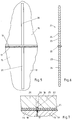
- FIGS The embodiments shown in Figures 1 and 2 Device 1 each have a carrier plate 2, on the Bottom of a longitudinal rail 3 and a plurality of cross rails 4 are arranged are.
- the cross rails 4 cross the longitudinal rail 3 at right angles and have a spacing 6 from one another. The distance 6 is approximately 20 centimeters.
- the individual cross rails 4 are each symmetrical to the longitudinal rail 3 arranged and have a on both sides of the longitudinal rail 3 Protrusion 7 on. The protrusion 7 is approximately 9 centimeters.
- an extension 8 of the longitudinal rail 3 is shown below. This serves to orient the device 1 relative to one another an already existing joint that is connected to the device 1 to be extended. Accordingly, the device 1 is in accordance with Figure 1 primarily intended for the formation of very long joints. In contrast, the device 1 according to Figure 2 is for training a joint as a predetermined breaking point in a screed layer provided in the area of a door opening. Your total length 9 is matched to the width of the door opening.
- the device 1 according to FIGS. 1 and 2 is used for insertion a defined joint between two screed panels with the Longitudinal rail 3 and for introducing merging into one another Incisions in the two screed panels with the cross rails 4. For this purpose, the device until the carrier plate 2 on the Surface of the screed rests, but not yet in the tough fully set screed pressed in. If the device 1 is removed again, a joint with internal dimensions remains, whose outer dimensions correspond to the longitudinal rail 3, and incisions, the outer dimensions of the cross rails 4th correspond in the screed back.
- the cross section the longitudinal rail 4 with the cross section of the longitudinal rail 3 in essential match.
- the cut reproduced Longitudinal rail 3 protrudes downwards by a height 10, which is the same size as a height 11 around which the cross rails 4 protrude downwards over the carrier plate 2.
- the heights 10 and 11 are about 3 centimeters.
- the width 12 of the longitudinal rail 3 is 5.5 millimeters and is not as big as the one here visible width of the cross rails 4.
- the longitudinal rail 3 and the Cross rails 4 are rounded at their lower edges 13 and 14, that is, tapered down to penetrate them to ease the screed.
- the embodiment of the longitudinal rail 3 and the transverse rails 4 4 differs from the embodiment in the following points according to Figure 3.
- the height 10 of the longitudinal rail 3 about 0.5 centimeters larger than the height 11 of the cross rails 4.
- the longitudinal rail 3 and the transverse rails 4 start up their bottom edges 13 and 14 pointed. Through both measures the penetration of the longitudinal rail 3 and the transverse rails 4 in the Screed even easier. So the higher altitude leads 10 to the fact that first the device 1 by the penetration of the Longitudinal rail 3 is fixed in the screed and only then greater force for additionally pressing in the cross rails 4 in the screed must be applied.
- the longitudinal rail 3 and the transverse rails 4 are preferably made of a plastic with a smooth surface. Is training with metal or other materials smooth surface conceivable, but it is good stability to ensure the lowest possible weight of the device 1 in order to ensure their ease of use.
- Figure 5 shows depressions in a screed layer 15, the with the device 1 were introduced after the setting of Screed layer 15.
- a joint introduced with the longitudinal rail 3 16 marks a predetermined breaking point with your reason.
- the crack 17 separates the screed layer 15 into two Screed panels 18 and 19.
- Over the joint 16 extends an incision 20 in the screed plates 18 and 19 with a the cross rails 4 was introduced.
- the incision 20 is in its inner dimensions on the outer dimensions of a connecting bolt 21 shown in FIG. 6 Voted.
- the connecting bolt 21 has one in the middle Collar 22, which is provided for engaging in the joint 16.
- the connecting bolt with grooves 23 is on both sides of the collar 22 provided that have a sawtooth-shaped longitudinal profile. Here are the transverse portions 24 of the sawtooth profile each facing the federal government 22.
- the Joint 16 and the incision 20 are cured with Two-component casting compound 25 filled, which is also a compound between the screed layer 15 or the screed plates 18 and 19 and the connecting bolt 21. Due to its shape, the connecting bolt 21 is anchored the two screed plates 18 and 19 together so that Relative shifts and other relative movements are not possible are. This prevents the hardened Two-component casting compound 25 from the joint 16 or the incision 20 is worked out. Rather, one that has been smoothed remains Surface 26 of the screed layer 15 including the area above the joint 16 or the cut 20 permanently flat.
Landscapes
- Engineering & Computer Science (AREA)
- Architecture (AREA)
- Civil Engineering (AREA)
- Structural Engineering (AREA)
- Physics & Mathematics (AREA)
- Electromagnetism (AREA)
- Road Paving Machines (AREA)
Abstract
Description
- Figur 1
- eine schematisierte Unteransicht einer ersten Ausführungsform der neuen Vorrichtung,
- Figur 2
- eine schematisierte Unteransicht einer zweiten Ausführungsform der neuen Vorrichtung,
- Figur 3
- einen Querschnitt durch eine Längsschiene der neuen Vorrichtung gemäß Figur 1 oder Figur 2 in einem gegenüber Figur 1 und Figur 2 vergrößertem Maßstab,
- Figur 4
- einen Figur 3 entsprechenden Querschnitt durch eine Längsschiene einer abgewandelten Ausführungsform der neuen Vorrichtung,
- Figur 5
- die Draufsicht auf eine mit der Vorrichtung gemäß Figur 4 in eine Estrichschicht eingebrachte Fuge und einen quer dazu verlaufenden Einschnitt,
- Figur 6
- ein Verankerungselement zum Einlegen in den Einschnitt gemäß Figur 5 und
- Figur 7
- einen Querschnitt durch das in den Einschnitt gemäß 5 eingelegte Verankerungselement gemäß Figur 6 nach dem Ausgießen des Einschnitts.
- 1
- - Trägerplatte
- 2
- - Trägerplatte
- 3
- - Längsschiene
- 4
- - Querschiene
- 5
- - Handgriff
- 6
- - Abstand
- 7
- - Überstand
- 8
- - Verlängerung
- 9
- - Gesamtlänge
- 10
- - Höhe
- 11
- - Höhe
- 12
- - Breite
- 13
- - Unterkante
- 14
- - Unterkante
- 15
- - Estrichschicht
- 16
- - Fuge
- 17
- - Riß
- 18
- - Estrichplatte
- 19
- - Estrichplatte
- 20
- - Einschnitt
- 21
- - Verbindungsbolzen
- 22
- - Bund
- 23
- - Rille
- 24
- - Abschnitt
- 25
- - Zweikomponentengießmasse
- 26
- - Oberfläche
Claims (10)
- Vorrichtung zum Ausbilden einer definierten Fuge als Sollbruchstelle zwischen zwei Estrichplatten, dadurch gekennzeichnet, daß eine Längsschiene (3) und mehrere Querschienen (4) vorgesehen sind, wobei die Längsschiene (3) und die Querschienen (4) eine Breite (12) von mindestens 3 mm aufweisen und wobei die Querschienen (4) die Längsschiene (3) in einem Abstand (6) von 10 bis 40 cm rechtwinklig kreuzen und um mindestens 4 cm auf beiden Seiten über die Längsschiene (3) überstehen.
- Vorrichtung nach Anspruch 1, dadurch gekennzeichnet, daß die Breite (12) der Längsschiene (3) und der Querschienen (4) mindestens 4 mm und vorzugsweise 5 bis 6 mm beträgt.
- Vorrichtung nach Anspruch 1 oder 2, dadurch gekennzeichnet, daß die Querschienen (4) um mindestens 6 cm und vorzugsweise um 8 bis 10 cm auf beiden Seiten über die Längsschiene (3) überstehen.
- Vorrichtung nach einem der Ansprüche 1 bis 3, dadurch gekennzeichnet, daß der Abstand (6) der Querschienen (3) untereinander 12 bis 30 cm und vorzugsweise 15 bis 25 cm beträgt.
- Vorrichtung nach einem der Ansprüche 1 bis 4, dadurch gekennzeichnet, daß sich die Breite (3) der Längsschiene (3) und der Querschienen (4) an ihren Unterkanten (13 und 14) nach unten hin verjüngt.
- Vorrichtung nach einem der Ansprüche 1 bis 5, dadurch gekennzeichnet, daß die Unterkanten (14) der Querschienen (4) oberhalb der Unterkante (13) der Längsschiene (3) angeordnet sind.
- Vorrichtung nach einem der Ansprüche 1 bis 6, dadurch gekennzeichnet, daß ein Anschlag zur Anlage an der Oberseite einer Estrichschicht (15) vorgesehen ist und daß die Längsschiene (3) und die Querschiene (4) um mindestens 2 cm und vorzugsweise um 2,5 bis 4 cm nach unten über den Anschlag überstehen.
- Vorrichtung nach Anspruch 7, dadurch gekennzeichnet, daß der Anschlag von einer Trägerplatte (2) ausgebildet ist, an deren Unterseite die Längsschiene (3) und die Querschienen (4) angeordnet sind und an deren Oberseite mindestens ein Handgriff (5) vorgesehen ist.
- Vorrichtung nach einem der Ansprüche 1 bis 8, dadurch gekennzeichnet, daß die Längsschiene (3) und die Querschienen (4) glatte Oberflächen aus Metall oder Kunststoff aufweisen.
- Verwendung einer Vorrichtung nach einem der Ansprüche 1 bis 9 beim Ausbilden einer definierten Fuge als Sollbruchstelle zwischen zwei Estrichplatten und zum Festlegen der ausgehärteten Estrichplatten aneinander, dadurch gekennzeichnet, daß die Längsschiene (3) zum Ausbilden der Fuge (16) zusammen mit den Querschienen (4) vorübergehend in eine noch nicht abgebundene Estrichschicht (15) eingedrückt wird, daß nach dem Aushärten der an die Fuge (16) angrenzenden Estrichplatten (18 und 19) Verbindungsbolzen (21) in die von den Querschienen (4) in den Estrichplatten (18 und 19) zurückbleibenden Einschnitte (20) eingelegt werden und daß dann die Fuge (16) und die Einschnitte (20) mit einer Gießmasse (25) ausgegossen werden.
Applications Claiming Priority (2)
| Application Number | Priority Date | Filing Date | Title |
|---|---|---|---|
| DE29616985U | 1996-09-30 | ||
| DE29616985U DE29616985U1 (de) | 1996-09-30 | 1996-09-30 | Vorrichtung zum Ausbilden einer definierten Fuge als Sollbruchstelle zwischen zwei Estrichplatten |
Publications (1)
| Publication Number | Publication Date |
|---|---|
| EP0833020A1 true EP0833020A1 (de) | 1998-04-01 |
Family
ID=8029928
Family Applications (1)
| Application Number | Title | Priority Date | Filing Date |
|---|---|---|---|
| EP97116128A Withdrawn EP0833020A1 (de) | 1996-09-30 | 1997-09-17 | Vorrichtung zum Ausbilden einer definierten Fuge als Sollbruchstelle zwischen zwei Estrichplatten und Verwendung der Vorrichtung |
Country Status (2)
| Country | Link |
|---|---|
| EP (1) | EP0833020A1 (de) |
| DE (1) | DE29616985U1 (de) |
Families Citing this family (1)
| Publication number | Priority date | Publication date | Assignee | Title |
|---|---|---|---|---|
| DE29616985U1 (de) * | 1996-09-30 | 1997-01-16 | Schmidt, Jürgen, 37127 Dransfeld | Vorrichtung zum Ausbilden einer definierten Fuge als Sollbruchstelle zwischen zwei Estrichplatten |
Citations (7)
| Publication number | Priority date | Publication date | Assignee | Title |
|---|---|---|---|---|
| DE221719C (de) * | ||||
| US1348639A (en) * | 1919-03-10 | 1920-08-03 | Grundmann William | Concrete-finishing tool |
| FR832160A (fr) * | 1937-04-29 | 1938-09-22 | Le Soliditit Francais | Procédé et appareil pour la confection des joints dans les revêtements en béton |
| CH361115A (de) * | 1957-11-08 | 1962-03-31 | Haggenmacher August | Verfahren und Vorrichtung zur Herstellung von Betonbelägen mit einlagefreien Trennfugen |
| GB1550369A (en) * | 1976-08-31 | 1979-08-15 | Tremix Eng Ltd | Device for forming a groove in newly laid concrete and the like |
| DE2904236A1 (de) * | 1979-02-05 | 1980-08-07 | Secuplan Belagtechnik Gmbh | Verfahren zur herstellung von standfesten und gradlinig verlaufenden fugenkanten fuer industriefussboden |
| DE29616985U1 (de) * | 1996-09-30 | 1997-01-16 | Schmidt, Jürgen, 37127 Dransfeld | Vorrichtung zum Ausbilden einer definierten Fuge als Sollbruchstelle zwischen zwei Estrichplatten |
-
1996
- 1996-09-30 DE DE29616985U patent/DE29616985U1/de not_active Expired - Lifetime
-
1997
- 1997-09-17 EP EP97116128A patent/EP0833020A1/de not_active Withdrawn
Patent Citations (7)
| Publication number | Priority date | Publication date | Assignee | Title |
|---|---|---|---|---|
| DE221719C (de) * | ||||
| US1348639A (en) * | 1919-03-10 | 1920-08-03 | Grundmann William | Concrete-finishing tool |
| FR832160A (fr) * | 1937-04-29 | 1938-09-22 | Le Soliditit Francais | Procédé et appareil pour la confection des joints dans les revêtements en béton |
| CH361115A (de) * | 1957-11-08 | 1962-03-31 | Haggenmacher August | Verfahren und Vorrichtung zur Herstellung von Betonbelägen mit einlagefreien Trennfugen |
| GB1550369A (en) * | 1976-08-31 | 1979-08-15 | Tremix Eng Ltd | Device for forming a groove in newly laid concrete and the like |
| DE2904236A1 (de) * | 1979-02-05 | 1980-08-07 | Secuplan Belagtechnik Gmbh | Verfahren zur herstellung von standfesten und gradlinig verlaufenden fugenkanten fuer industriefussboden |
| DE29616985U1 (de) * | 1996-09-30 | 1997-01-16 | Schmidt, Jürgen, 37127 Dransfeld | Vorrichtung zum Ausbilden einer definierten Fuge als Sollbruchstelle zwischen zwei Estrichplatten |
Also Published As
| Publication number | Publication date |
|---|---|
| DE29616985U1 (de) | 1997-01-16 |
Similar Documents
| Publication | Publication Date | Title |
|---|---|---|
| EP0805240A1 (de) | Bausatz für eine Wand | |
| EP0194435A2 (de) | Vorrichtung zur Bildung von Dehnungsfugen in Estrich- oder Betonflächen | |
| EP3929376A1 (de) | Dehnungsfugenprofilsystem | |
| DE29822362U1 (de) | Dämmstoffbahn | |
| DE29917134U1 (de) | Schalungselement | |
| DE2455775C3 (de) | Dehnfugenleiste für Estrichböden | |
| EP0617182B1 (de) | Mehrzweckleiste aus Kunststoff | |
| EP0833020A1 (de) | Vorrichtung zum Ausbilden einer definierten Fuge als Sollbruchstelle zwischen zwei Estrichplatten und Verwendung der Vorrichtung | |
| DE20003804U1 (de) | Wärmedämmelement aus einem geschäumten Kunststoffmaterial | |
| DE10304622B3 (de) | Verfahren zum Errichten einer Schalung für Betonteile | |
| DE10054978B4 (de) | Gipskarton-Platte mit einer randseitingen, sich über die ganze Länge eines Seitenrandes erstreckende Ausnehmung, Verfahren zur Herstellung und Verwendung derselben | |
| DE10311894A1 (de) | Belag, bestehend aus einzelnen Platten aus mineralischem Material | |
| EP0003720B2 (de) | Verfahren zum rissicheren, dichten Anschluss eines Asphaltbelages an einen Bauteil, Satz von Profilen zur Durchführung dieses Verfahrens und nach dem Verfahren erstellte Baukonstruktion | |
| DE8717484U1 (de) | Plasterförmiger Betonstein | |
| DE3726216A1 (de) | Fertigboden aus beton-platten, insbesondere aus ortbeton-platten bestehender industrieboden und verfahren zu dessen herstellung | |
| DE19857817B4 (de) | Dämmstoffbahn | |
| DE19918143A1 (de) | Beton-Pflasterelement sowie Verfahren und Vorrichtung zum Herstellen desselben | |
| DE19537977C2 (de) | Verfahren zum seitlichen Einputzen eines Treppenpodestes | |
| DE2251621C2 (de) | Verbundbelag mit Verlegeeinheiten und Verfahren zum Herstellen des Verbundbelages | |
| EP4038238B1 (de) | Pflasterstein aus beton, pflasterverband und verfahren zum herstellen eines pflastersteins | |
| DE3230928A1 (de) | Vorrichtung zur herstellung einer dehnfuge | |
| DE3036620C2 (de) | Vorrichtung zum Schutz von Bauwerksteilen aus Beton gegen Feuchtigkeit | |
| DE19982708B4 (de) | Verfahren zur Herstellung einer Betonfahrbahndecke mit Dübel | |
| AT391730B (de) | Daemmplatte, insbesondere aus mineralfasern | |
| DE2404082A1 (de) | Plattenfoermiges bauelement aus beton fuer insbesondere deckwerke |
Legal Events
| Date | Code | Title | Description |
|---|---|---|---|
| PUAI | Public reference made under article 153(3) epc to a published international application that has entered the european phase |
Free format text: ORIGINAL CODE: 0009012 |
|
| AK | Designated contracting states |
Kind code of ref document: A1 Designated state(s): BE CH DE FR GB LI NL |
|
| AX | Request for extension of the european patent |
Free format text: AL;LT;LV;RO;SI |
|
| 17P | Request for examination filed |
Effective date: 19981001 |
|
| AKX | Designation fees paid |
Free format text: BE CH DE FR GB LI NL |
|
| RBV | Designated contracting states (corrected) |
Designated state(s): BE CH DE FR GB LI NL |
|
| 17Q | First examination report despatched |
Effective date: 20020314 |
|
| GRAP | Despatch of communication of intention to grant a patent |
Free format text: ORIGINAL CODE: EPIDOSNIGR1 |
|
| RTI1 | Title (correction) |
Free format text: DEVICE FOR THE ESTABLISHMENT OF A DEFINED JOINT AS PREDETERMINED BREAKING POINT BETWEEN TWO PLATES OF FLOOR CEMENT, USE O |
|
| STAA | Information on the status of an ep patent application or granted ep patent |
Free format text: STATUS: THE APPLICATION IS DEEMED TO BE WITHDRAWN |
|
| 18D | Application deemed to be withdrawn |
Effective date: 20040928 |