EP0833040A2 - Fixation circonférencielle d'un anneau d'étanchéité avec jeu radial variable - Google Patents
Fixation circonférencielle d'un anneau d'étanchéité avec jeu radial variable Download PDFInfo
- Publication number
- EP0833040A2 EP0833040A2 EP97307304A EP97307304A EP0833040A2 EP 0833040 A2 EP0833040 A2 EP 0833040A2 EP 97307304 A EP97307304 A EP 97307304A EP 97307304 A EP97307304 A EP 97307304A EP 0833040 A2 EP0833040 A2 EP 0833040A2
- Authority
- EP
- European Patent Office
- Prior art keywords
- segments
- segment
- stationary component
- axis
- component
- Prior art date
- Legal status (The legal status is an assumption and is not a legal conclusion. Google has not performed a legal analysis and makes no representation as to the accuracy of the status listed.)
- Granted
Links
- 238000006073 displacement reaction Methods 0.000 title claims abstract description 21
- 238000012856 packing Methods 0.000 title description 7
- 230000005484 gravity Effects 0.000 claims abstract description 20
- 238000007789 sealing Methods 0.000 abstract description 9
- 239000012530 fluid Substances 0.000 description 4
- 230000004888 barrier function Effects 0.000 description 2
- 238000009825 accumulation Methods 0.000 description 1
- 230000000694 effects Effects 0.000 description 1
- 238000009434 installation Methods 0.000 description 1
- 238000004519 manufacturing process Methods 0.000 description 1
- 239000000463 material Substances 0.000 description 1
- 230000002265 prevention Effects 0.000 description 1
- 230000007704 transition Effects 0.000 description 1
Images
Classifications
-
- F—MECHANICAL ENGINEERING; LIGHTING; HEATING; WEAPONS; BLASTING
- F01—MACHINES OR ENGINES IN GENERAL; ENGINE PLANTS IN GENERAL; STEAM ENGINES
- F01D—NON-POSITIVE DISPLACEMENT MACHINES OR ENGINES, e.g. STEAM TURBINES
- F01D11/00—Preventing or minimising internal leakage of working-fluid, e.g. between stages
- F01D11/02—Preventing or minimising internal leakage of working-fluid, e.g. between stages by non-contact sealings, e.g. of labyrinth type
- F01D11/025—Seal clearance control; Floating assembly; Adaptation means to differential thermal dilatations
-
- F—MECHANICAL ENGINEERING; LIGHTING; HEATING; WEAPONS; BLASTING
- F01—MACHINES OR ENGINES IN GENERAL; ENGINE PLANTS IN GENERAL; STEAM ENGINES
- F01D—NON-POSITIVE DISPLACEMENT MACHINES OR ENGINES, e.g. STEAM TURBINES
- F01D25/00—Component parts, details, or accessories, not provided for in, or of interest apart from, other groups
- F01D25/24—Casings; Casing parts, e.g. diaphragms, casing fastenings
- F01D25/246—Fastening of diaphragms or stator-rings
-
- F—MECHANICAL ENGINEERING; LIGHTING; HEATING; WEAPONS; BLASTING
- F16—ENGINEERING ELEMENTS AND UNITS; GENERAL MEASURES FOR PRODUCING AND MAINTAINING EFFECTIVE FUNCTIONING OF MACHINES OR INSTALLATIONS; THERMAL INSULATION IN GENERAL
- F16J—PISTONS; CYLINDERS; SEALINGS
- F16J15/00—Sealings
- F16J15/44—Free-space packings
- F16J15/441—Free-space packings with floating ring
- F16J15/442—Free-space packings with floating ring segmented
Definitions
- the present invention relates to seals between rotating and stationary components of a rotary machine, such as a steam turbine, and particularly relates to positive pressure, variable clearance packing ring segments having guides for preventing circumferential slippage of the segments about the groove of the stationary component and enabling the segments to move toward and away from the rotating component, i.e., between large and small clearance positions relative to the rotating component.
- seals are provided between rotating and stationary components.
- seals are provided between rotating and stationary components.
- the arcuate seal ring segments are disposed in an annular groove in the stationary component concentric about the axis of rotation of the machine and hence concentric to the sealing surface of the rotating component.
- Each arcuate seal segment carries an arcuate seal face in opposition to the sealing surface of the rotating component.
- the seal faces carry a radially directed array of axially spaced teeth and which teeth are radially spaced from an array of axially spaced annular grooves forming the sealing surface of the rotating component.
- the rotating component may have a smooth surface in radial opposition to the array of teeth on the seal faces.
- the sealing function is achieved by creating turbulent flow of a working media, for example, steam, as it passes through the relatively tight clearances within the labyrinth defined by the seal face teeth and the opposing surface of the rotating component.
- the annular groove is dovetail-shaped, having locating flanges directed axially toward one another and defining a slot therebetween.
- the stationary component e.g., a housing or casing
- the stationary component is typically split lengthwise along a generally horizontal extending midline defining upper and lower halves of the stationary housing.
- the semi-annular dovetail grooves receive portions of the arcuate seal ring segments.
- the seal ring segments are similarly dovetail-shaped, having a pair of flanges directed axially away from one another for disposition within the dovetail groove and a neck which joins the seal face and the flanges of the segment and passes through the slot defined by the locating flanges of the groove.
- the neck carries the arcuate seal face radially inwardly of the groove when each segment is installed.
- the segments are typically spring biased into outer or large clearance positions with the seal faces carried thereby spaced substantially outwardly of the rotary component.
- the springs displace the segments radially outwardly.
- the working fluid medium e.g., steam
- the segments are retracted to their large clearance positions during startup and turbine shutdown by the springs, the gaps between the end faces of adjoining segments become increasingly greater.
- the gaps between the end faces of the segments decrease substantially to a fully-closed position when the segments obtain their smallest diameter.
- the segments are disposed within the grooves of the stationary component in a sliding or piston-fit arrangement.
- the side segments in the upper housing and the side segments of the lower housing may slide under the action of gravity forces such that the side segments of the lower housing engage the lowermost central segment in the lower housing of the machine, with the accumulated clearance between the end faces appearing between the uppermost segment in the upper housing and one or both of the side segments of the upper housing.
- the segments Upon startup, the segments are designed to move under fluid pressure from their radially outward positions to their radially inward positions. Because of the effect of gravity, the segments tend to move in sequence. First, the top segment moves radially inwardly, followed by the side segments of the upper housing. The side segments of the lower housing then move radially inwardly, followed by the lowermost segment. It has been found, however, that because the segments become displaced circumferentially about the groove of the stationary component by gravity forces, the inward movement of the side segments of the lower housing of the stationary component, essentially in an upward radial direction, precludes or blocks radial inward movement of the lowermost segment.
- the fluid pressure forces tending to displace the lowermost segment radially inwardly are insufficient to displace the lower side segments in a generally upward circumferential direction to enable the lowermost segment to move into its radially innermost position. Consequently, the lowermost segment remains radially displaced from its designed radially inward position resulting in a larger than desired clearance between its sealing face and the rotary component.
- the seal segments are biased outwardly by the springs between the segment ends and inwardly by fluid pressure forces.
- the gravity springs function such that the segments have little or no weight, permitting closure of the lower seal segments to the inner Dosition.
- the lower seal seqments are said to float by virtue of their opposing circumferential and gravity spring forces and such segments move radially inwardly and outwardly.
- the end circumferential springs bearing against the anti-rotation keys bias the lower seal segments for circumferential displacement within the grooves in contrast to the present invention wherein circumferential displacement of the lower side segments is positively prevented and horizontal, rather than radial, movement of the lower side segments between inner and outer positions is provided.
- each of the side segments in the lower housing of the casing is provided with a guide which supports the segment, prevents the segment from circumferential displacement under gravity forces, and enables the segment to slide horizontally between outer large and inner small clearance positions, respectively.
- each guide comprises an angle bracket, one leg of which is secured to the outer face of the segment adjacent the end of the segment near the midline of the rotary machine.
- the generally horizontally projecting other leg of the bracket is received in a recess formed in the interior surface of the stationary component and rests on a stop carried by the stationary component. The stops prevent downward circumferential displacement of the side segments in the groove of the lower housing of the rotary machine and thereby maintain clearance between the butt ends of adjacent packing segments.
- the bracket also supports the side segments of the lower housing of the machine for movement in a generally horizontal direction toward and away from a vertical plane through the axis of the machine.
- each side segment moves as a unit horizontally toward and away from the rotary component.
- apparatus for preventing circumferential displacement of a segment disposed in a stationary component of a rotary machine having a component rotatable about an axis, the stationary component having an annular groove about the axis, at least one axially directed locating flange about the axis and in part defining a slot opening into the groove, and a stop
- the apparatus comprising a segment body for forming one of a plurality of annular segments about the axis of the machine and for partial disposition in the groove of the stationary component, the segment body having an arcuate seal face, at least one axially directed flange for disposition in the groove and a neck portion receivable in the slot and interconnecting the flange and the seal face and a member carried by the segment body and projecting generally outwardly thereof for engagement with the stop carried by the stationary component for preventing circumferential displacement of the segment body about the groove.
- a rotary machine comprising a component rotatable about an axis, a stationary component including an annular groove about the axis, the stationary component having at least one axially directed locating flange about the axis and in part defining a slot opening into the groove, a plurality of generally annular segments about the axis, each segment having an arcuate seal face, at least one axially directed flange disposed in the groove and a neck portion in the slot and interconnecting the flange and the seal face, certain of the plurality of segments being movable between radial outward and radial inward positions relative to the axis, a member engaging between the stationary component and each of a pair of the plurality of segments on respective opposite sides of the stationary component for supporting the pair of segments for movement generally horizontally toward and away from a vertical plane through the axis between inner and outer positions, respectively, the pair of segments comprising different ones of the plurality of segments than the certain segments.
- a rotary machine comprising a component rotatable about an axis, a stationary component including an annular groove about the axis, the stationary component comprising upper and lower housings joined to one another along a generally horizontal midline of the stationary component, the stationary component having a pair of axially directed locating flanges about the axis and extending axially toward one another, the flanges defining a slot opening into the groove, a plurality of generally annular segments about the axis, each segment having an arcuate seal face, a pair of flanges disposed in the groove and extending axially away from one another and a neck portion in the slot and interconnecting the segment flanges and the seal faces, at least three of the plurality of segments being disposed in each of the upper and lower housings and forming a circumferentially extending seal ring about the rotatable component, the segments being movable between outward large and inward small clearance positions
- annular seal segments about the stationary component are prevented from circumferential displacement due to gravity forces, thereby enabling the segments to close about the rotary component effecting the seal, rather than binding up and preventing seal closure.
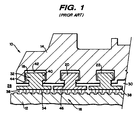
- a rotary machine for example, a steam turbine, generally designated 10, having a rotary component, e.g., a turbine shaft 12, disposed in a stationary component, e.g., a turbine housing 14 and which shaft 12 is supported for rotation by conventional means, not shown, within turbine housing 14.
- a multi-stage labyrinth seal 16 including a plurality of seal rings 18, 20 and 22 are disposed about turbine shaft 12, separating high and low pressure regions 28 and 30, respectively.
- Each seal ring is formed of an annular array of a plurality of arcuate seal segments 32.
- labyrinth seal 16 functions by placing a relatively large number of partial barriers to the flow of steam from the high pressure region 28 to the low pressure region 30.
- each seal ring segment 32 thus has a sealing face 34 with projecting radial teeth 36.
- the sealing face 34 is formed by a pair of flanges 38 extending axially away from one another, although it will be appreciated that only one such flange 38 is necessary in certain applications.
- the outer portions of the seal ring segments 32 include locating hooks or flanges 40 which similarly extend from segment 32 in axially opposite directions away from one another.
- the stationary component i.e., turbine housing 14 has a generally dovetail-shaped annular groove 42 at each axial location of the seal.
- the annular groove 42 is located along radially innermost portions of the housing 14 by a pair of locating flanges 44 which extend axially toward one another defining a slot 46 therebetween.
- a neck 48 of each segment 32 interconnects the locating flanges or hooks 40 and the sealing face 34 and extends through the slot 46.
- the segments 32 preferably comprise positive pressure, variable clearance packing ring segments movable between open outermost large clearance and closed innermost small clearance positions about the rotary component, e.g., the turbine shaft, at startup and at speed operations, respectively.
- the segments are moved to their open outermost largest diameter positions by springs, not shown, disposed between the locating flanges or hooks 40 of the segments and the locating flanges 44 of the stationary component 14.
- springs not shown
- a plurality of passages are provided in the stationary component or segments to introduce the flowing medium, for example, steam, in the groove 42 and along the outer face of the segments whereby the segments may be displaced inwardly toward the rotary component against the bias of the springs.
- This type of positive pressure variable clearance packing ring segment is conventional in the art, for example, as described and illustrated in U.S. Patent No. 4,374,068.
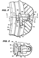
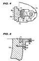
- each segment 32L between the locating hooks 40 and adjacent its upper end is provided with a flat 50 and a recess 52.
- a groove 54 is formed along the inner surface of the stationary component 14L adjacent the midline of the housings 14U and 14L and which groove forms a stop or a ledge 56.
- a support member 58 engages between the segment 32L and the lower housing of the stationary component.
- the support member comprises an angle bracket having right angularly related legs 60 and 62.
- the leg 60 receives a bolt 64 for securing the bracket 60 to the upper end of the lowermost segment 32L.
- a projection 66 along the inner face of the leg 60 engages in the recess 52 of the segment 32L to stabilize the bracket.
- the other leg 62 of the bracket 60 has an adjustable set screw 68 which extends below the lower surface of leg 62 for engagement on stop 56. It will be appreciated from the foregoing and a review of Figure 2 that the brackets 58 thus support the entirety of the segments 32L against downward circumferential displacement within the groove 42 along opposite sides of the lower housing 14L.
- Set screw 68 compensates for the normal manufacturing tolerances whereby the various segments 32 may not all be of exactly the same length.
- Each bracket 58 is disposed to enable horizontal sliding movement of the associated segment 32L in relation to the rotary component, i.e., the rotor of the turbine.
- the segments 32L on the opposite sides of the lower housing 14L move horizontally toward and away from a vertical plane through the axis of the shaft between their innermost smallest clearance and outermost largest clearance positions, respectively.
- the displacement of bracket 58 is horizontal, not radial. It is a horizontal movement in contrast to the radial direction of movement of the remaining segments about the stationary component in both the upper and lower housings of the stationary component.
- the end faces of the upper and lower side segments 32U and 32L abut one another.
- a tongue 70 is received in a slot 72 formed in the opposed end faces and maintains the segments 32U and 32L in substantial circumferential alignment with one another.
- the motion of segments 32U may have a minor horizontal component of travel.
- a plate 80 is secured in a matching recess 82 formed along the interior surface of the upper housing 14U at each substantially diametrically opposed side of the upper housing 14U adjacent the midline.
- the plate 80 is secured by a bolt and projects inwardly to reside in a slot 86 formed along the lower end of the upper side segment 32U.
- the plate 80 is conventional in this type of packing ring and is engaged by the side segments 32U upon removal of the upper housing 14U, thus preventing the segments in the upper housing of the stationary component from falling out when the upper housing is removed from the lower housing.
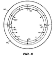
- the segments 32U and 32L are illustrated in the upper and lower housings 14U and 14L. As illustrated in that figure, six segments are shown, with three segments in the upper housing 14U and three segments in the lower housing 14L. Previous to the present invention, the segments 32 would theoretically all move radially inwardly and outwardly between closed and open positions, respectively, about the shaft. However, because the segments may be displaced by gravity during shutdown prior to startup or during transition, it has been discovered that the segments and particularly the lowermost segment in the lower housing 14L may not move inwardly to its closed position. As explained previously, this is caused by the segments slipping circumferentially downwardly in the grooves under gravity forces.
- brackets 58 are provided for supporting the side segments 32L of the lower housing 14L against downward displacement in the grooves due to gravity, while simultaneously those segments are enabled for movement between closed and open positions relative to the rotating shaft.
- the radial directions of movement of the upper segments, as well as the lowermost segment in accordance with the present invention, are indicated by the arrows 90.
- the side segments 32L of the lower housing 14L move horizontally, as indicated by the arrows 92. As previously noted, there may also be some small horizontal component of motion in segments 32U.
Landscapes
- Engineering & Computer Science (AREA)
- General Engineering & Computer Science (AREA)
- Mechanical Engineering (AREA)
- Turbine Rotor Nozzle Sealing (AREA)
- Sealing Using Fluids, Sealing Without Contact, And Removal Of Oil (AREA)
- Sealing Devices (AREA)
Applications Claiming Priority (2)
| Application Number | Priority Date | Filing Date | Title |
|---|---|---|---|
| US721655 | 1996-09-27 | ||
| US08/721,655 US5709388A (en) | 1996-09-27 | 1996-09-27 | Variable clearance packing ring with guide for preventing circumferential displacement |
Publications (3)
| Publication Number | Publication Date |
|---|---|
| EP0833040A2 true EP0833040A2 (fr) | 1998-04-01 |
| EP0833040A3 EP0833040A3 (fr) | 1999-11-03 |
| EP0833040B1 EP0833040B1 (fr) | 2003-12-03 |
Family
ID=24898779
Family Applications (1)
| Application Number | Title | Priority Date | Filing Date |
|---|---|---|---|
| EP97307304A Expired - Lifetime EP0833040B1 (fr) | 1996-09-27 | 1997-09-19 | Fixation circonférencielle d'un anneau d'étanchéité avec jeu radial variable |
Country Status (6)
| Country | Link |
|---|---|
| US (1) | US5709388A (fr) |
| EP (1) | EP0833040B1 (fr) |
| JP (1) | JP4117927B2 (fr) |
| KR (1) | KR100520011B1 (fr) |
| CA (1) | CA2214679A1 (fr) |
| DE (1) | DE69726533T2 (fr) |
Cited By (1)
| Publication number | Priority date | Publication date | Assignee | Title |
|---|---|---|---|---|
| GB2365077A (en) * | 2000-07-21 | 2002-02-13 | Gen Electric | Support system for turbine diaphragms |
Families Citing this family (37)
| Publication number | Priority date | Publication date | Assignee | Title |
|---|---|---|---|---|
| US6022027A (en) * | 1997-12-18 | 2000-02-08 | General Electric Co. | Variable clearance packing ring with clips for preventing circumferential displacement |
| US6220603B1 (en) * | 1998-07-13 | 2001-04-24 | Ronald Earl Brandon | Non retractable segmented packing ring for fluid turbines having special springs to reduce forces during shaft rubbing |
| EP1243755A1 (fr) * | 2001-03-16 | 2002-09-25 | Ronald E. Brandon | Turbine à fluide élastique employant un anneau d'étanchéité |
| US6695316B2 (en) | 2001-09-21 | 2004-02-24 | General Electric Company | Apparatus and methods for supporting a retractable packing ring |
| US6651986B2 (en) | 2002-01-29 | 2003-11-25 | General Electric Company | Retractable packing ring lower half segment retaining key and method for retaining retractable packing ring lower half segment |
| US6935634B2 (en) * | 2003-05-08 | 2005-08-30 | General Electric Company | Steam turbine packing spring |
| JP4822716B2 (ja) * | 2005-02-07 | 2011-11-24 | 三菱重工業株式会社 | シール構造を備えたガスタービン |
| US20070040335A1 (en) * | 2005-08-22 | 2007-02-22 | General Electric Company | Axially adjustable sealing ring |
| US7344357B2 (en) * | 2005-09-02 | 2008-03-18 | General Electric Company | Methods and apparatus for assembling a rotary machine |
| US7641200B2 (en) * | 2005-11-28 | 2010-01-05 | General Electric Company | Variable clearance packing ring arrangement |
| US20070120329A1 (en) * | 2005-11-29 | 2007-05-31 | Chevrette Richard J | Apparatus and method for steam turbine variable clearance packing |
| US7704041B2 (en) * | 2006-04-07 | 2010-04-27 | General Electric Company | Variable clearance positive pressure packing ring and carrier arrangement with coil type spring |
| US7384235B2 (en) * | 2006-04-07 | 2008-06-10 | General Electric Company | Variable clearance positive pressure packing ring and carrier arrangement with leaf springs |
| US7484927B2 (en) * | 2006-04-14 | 2009-02-03 | General Electric Company | Steam turbine variable clearance packing |
| US7731478B2 (en) * | 2006-05-25 | 2010-06-08 | General Electric Company | Method and apparatus for variable clearance packing |
| US8181967B2 (en) * | 2006-06-27 | 2012-05-22 | General Electric Company | Variable clearance packing ring |
| US20080042367A1 (en) * | 2006-08-17 | 2008-02-21 | General Electric Company | A variable clearance packing ring |
| US8540479B2 (en) * | 2007-01-11 | 2013-09-24 | General Electric Company | Active retractable seal for turbo machinery and related method |
| US7909335B2 (en) * | 2008-02-04 | 2011-03-22 | General Electric Company | Retractable compliant plate seals |
| US8740225B2 (en) * | 2009-06-03 | 2014-06-03 | Exponential Technologies, Inc. | Hydrodynamic bore seal |
| JP5460234B2 (ja) * | 2009-10-19 | 2014-04-02 | 株式会社東芝 | 高圧蒸気タービンのグランドシール装置 |
| JP5449976B2 (ja) * | 2009-10-20 | 2014-03-19 | 株式会社東芝 | 軸シール装置およびタービン装置並びに軸シール装置間隙調整方法 |
| US8398090B2 (en) | 2010-06-09 | 2013-03-19 | General Electric Company | Spring loaded seal assembly for turbines |
| US8628092B2 (en) | 2010-11-30 | 2014-01-14 | General Electric Company | Method and apparatus for packing rings |
| US8834113B2 (en) * | 2011-07-19 | 2014-09-16 | General Electric Company | Alignment member for steam turbine nozzle assembly |
| US9382813B2 (en) * | 2012-12-04 | 2016-07-05 | General Electric Company | Turbomachine diaphragm ring with packing retainment apparatus |
| US9441498B2 (en) | 2013-10-30 | 2016-09-13 | Siemens Energy, Inc. | Process and tool for aligning a seal housing assembly with a casing of a gas turbine engine |
| KR20160117571A (ko) * | 2014-03-06 | 2016-10-10 | 미츠비시 히타치 파워 시스템즈 가부시키가이샤 | 지지 장치, 터빈 및 지지 방법 |
| US20150285152A1 (en) * | 2014-04-03 | 2015-10-08 | United Technologies Corporation | Gas turbine engine and seal assembly therefore |
| JP6509008B2 (ja) * | 2015-03-30 | 2019-05-08 | 三菱日立パワーシステムズ株式会社 | 支持装置、タービン、回転機械の組立方法、及び回転機械の分解方法 |
| US10138749B2 (en) * | 2016-03-16 | 2018-11-27 | United Technologies Corporation | Seal anti-rotation feature |
| PL3284919T3 (pl) * | 2016-08-16 | 2024-12-09 | General Electric Technology Gmbh | Turbina o przepływie osiowym mająca kryzę podzieloną na dwie połowy w płaszczyźnie połączenia |
| JP6941012B2 (ja) * | 2017-09-05 | 2021-09-29 | 三菱重工コンプレッサ株式会社 | 圧縮機及び圧縮機組み立て方法 |
| KR20200108282A (ko) | 2017-12-13 | 2020-09-17 | 엑스퍼넨셜 테크놀로지스 주식회사 | 회전식 유체 유동 장치 |
| US11168683B2 (en) | 2019-03-14 | 2021-11-09 | Exponential Technologies, Inc. | Pressure balancing system for a fluid pump |
| GB2605563B (en) * | 2021-03-15 | 2024-09-04 | Crane John Uk Ltd | A radial separation seal |
| CN113606345B (zh) * | 2021-06-21 | 2024-11-19 | 东方电气集团东方汽轮机有限公司 | 一种气封组件及气封圈 |
Citations (3)
| Publication number | Priority date | Publication date | Assignee | Title |
|---|---|---|---|---|
| US4374068A (en) | 1981-10-15 | 1983-02-15 | Milliken Research Corporation | Process for hydroxyalkylation of cyanoethylanilines |
| US5395124A (en) | 1993-01-04 | 1995-03-07 | Imo Industries, Inc. | Retractible segmented packing ring for fluid turbines having gravity springs to neutralize packing segment weight forces |
| US5464226A (en) | 1993-12-06 | 1995-11-07 | Demag Delaval Turbomachinery Corp. Turbocare Division | Retractable packing rings for steam turbines |
Family Cites Families (12)
| Publication number | Priority date | Publication date | Assignee | Title |
|---|---|---|---|---|
| GB277806A (en) * | 1926-09-29 | 1927-09-29 | English Electric Co Ltd | Improvements in glands or other packing devices for rotary shafts |
| US2239637A (en) * | 1940-04-30 | 1941-04-22 | John H Zesewitz | Spindle seal for fluid pressure motors |
| US2600991A (en) * | 1949-06-14 | 1952-06-17 | Gen Electric | Labyrinth seal arrangement |
| DE1226379B (de) * | 1961-11-07 | 1966-10-06 | Licentia Gmbh | Rotordichtung mit Dichtringsegmenten |
| US3155395A (en) * | 1963-09-12 | 1964-11-03 | Gen Electric | Shaft packing assembly |
| US3642292A (en) * | 1969-05-21 | 1972-02-15 | Denis E Dougherty | Sealing arrangement |
| US3829233A (en) * | 1973-06-27 | 1974-08-13 | Westinghouse Electric Corp | Turbine diaphragm seal structure |
| GB2092243B (en) * | 1981-01-31 | 1984-12-05 | Rolls Royce | Non-contacting gas seal |
| US4436311A (en) * | 1982-04-20 | 1984-03-13 | Brandon Ronald E | Segmented labyrinth-type shaft sealing system for fluid turbines |
| US5374068A (en) * | 1991-05-07 | 1994-12-20 | General Electric Co. | Method for providing uniform radial clearance of labyrinth seals between rotating and stationary components |
| US5487491A (en) * | 1993-06-07 | 1996-01-30 | Sealright Company, Inc. | Cartridge dispenser with interior bag and interlocking lid |
| US5487549A (en) * | 1994-10-24 | 1996-01-30 | Demag Delaval Turbomachinery Corp. Turbocare Division | Turbine interfitting packing with cam adjustment |
-
1996
- 1996-09-27 US US08/721,655 patent/US5709388A/en not_active Expired - Lifetime
-
1997
- 1997-09-04 CA CA002214679A patent/CA2214679A1/fr not_active Abandoned
- 1997-09-08 JP JP24233597A patent/JP4117927B2/ja not_active Expired - Lifetime
- 1997-09-19 EP EP97307304A patent/EP0833040B1/fr not_active Expired - Lifetime
- 1997-09-19 DE DE69726533T patent/DE69726533T2/de not_active Expired - Lifetime
- 1997-09-26 KR KR1019970049026A patent/KR100520011B1/ko not_active Expired - Lifetime
Patent Citations (3)
| Publication number | Priority date | Publication date | Assignee | Title |
|---|---|---|---|---|
| US4374068A (en) | 1981-10-15 | 1983-02-15 | Milliken Research Corporation | Process for hydroxyalkylation of cyanoethylanilines |
| US5395124A (en) | 1993-01-04 | 1995-03-07 | Imo Industries, Inc. | Retractible segmented packing ring for fluid turbines having gravity springs to neutralize packing segment weight forces |
| US5464226A (en) | 1993-12-06 | 1995-11-07 | Demag Delaval Turbomachinery Corp. Turbocare Division | Retractable packing rings for steam turbines |
Cited By (2)
| Publication number | Priority date | Publication date | Assignee | Title |
|---|---|---|---|---|
| GB2365077A (en) * | 2000-07-21 | 2002-02-13 | Gen Electric | Support system for turbine diaphragms |
| GB2365077B (en) * | 2000-07-21 | 2005-02-02 | Gen Electric | Turbine diaphragm support system |
Also Published As
| Publication number | Publication date |
|---|---|
| KR19980025023A (ko) | 1998-07-06 |
| JP4117927B2 (ja) | 2008-07-16 |
| MX9707407A (es) | 1998-06-30 |
| KR100520011B1 (ko) | 2005-12-21 |
| CA2214679A1 (fr) | 1998-03-27 |
| DE69726533T2 (de) | 2004-09-30 |
| JPH10153265A (ja) | 1998-06-09 |
| DE69726533D1 (de) | 2004-01-15 |
| EP0833040B1 (fr) | 2003-12-03 |
| EP0833040A3 (fr) | 1999-11-03 |
| US5709388A (en) | 1998-01-20 |
Similar Documents
| Publication | Publication Date | Title |
|---|---|---|
| EP0833040B1 (fr) | Fixation circonférencielle d'un anneau d'étanchéité avec jeu radial variable | |
| US6022027A (en) | Variable clearance packing ring with clips for preventing circumferential displacement | |
| US6651986B2 (en) | Retractable packing ring lower half segment retaining key and method for retaining retractable packing ring lower half segment | |
| US6695316B2 (en) | Apparatus and methods for supporting a retractable packing ring | |
| US6065754A (en) | Uniform clearance, temperature responsive, variable packing ring | |
| US6250641B1 (en) | Positive biased packing ring brush seal combination | |
| US7344357B2 (en) | Methods and apparatus for assembling a rotary machine | |
| US7704041B2 (en) | Variable clearance positive pressure packing ring and carrier arrangement with coil type spring | |
| EP1384856B1 (fr) | Etanchéification de la fente entre les surfaces terminales des segments de garniture d'étanchéité de turbine à vapeur et rétrofit des segments correspondants | |
| US7946591B2 (en) | Combined labyrinth seal and screw-type gasket bearing sealing arrangement | |
| EP1860356B1 (fr) | Procédé et appareil pour garniture à jeu variable | |
| GB2439635A (en) | A variable clearance packing ring for a seal | |
| RU2258145C2 (ru) | Способ для точного размещения в радиальном направлении щеточного уплотнения турбины и устройство для его осуществления (варианты) | |
| EP1847737A2 (fr) | Cerclage d'emballage à pression positive et espace variable et agencement de support avec ressort à lames | |
| WO2001057420A1 (fr) | Combinaison de joint a brosse toroidale et de bague d'etancheite sollicitee positivement | |
| KR20070102415A (ko) | 패킹 링 조립체 및 증기 터빈 | |
| UA61055C2 (en) | Seal node | |
| EP1790886B1 (fr) | Anneau d'étanchéité à jeu variable | |
| EP4374094A1 (fr) | Ensemble joint à labyrinthe divisé en polymère | |
| EP1169585B1 (fr) | Joint brosse auto-centreur | |
| US6131913A (en) | Anti-rotation and axial locking arrangement of a gas seal on its sleeve | |
| KR100569648B1 (ko) | 원주 방향의 변위를 방지하기 위한 클립을 구비하는 가변간극의 패킹 링 | |
| EP1890060A1 (fr) | Anneau de conditionnement à jeu variable | |
| MXPA97007407A (en) | Variable clearance packaging ring with guide to prevent circunferenc displacement | |
| US20070120329A1 (en) | Apparatus and method for steam turbine variable clearance packing |
Legal Events
| Date | Code | Title | Description |
|---|---|---|---|
| PUAI | Public reference made under article 153(3) epc to a published international application that has entered the european phase |
Free format text: ORIGINAL CODE: 0009012 |
|
| AK | Designated contracting states |
Kind code of ref document: A2 Designated state(s): CH DE FR GB IT LI |
|
| AX | Request for extension of the european patent |
Free format text: AL;LT;LV;RO;SI |
|
| DAX | Request for extension of the european patent (deleted) | ||
| PUAL | Search report despatched |
Free format text: ORIGINAL CODE: 0009013 |
|
| AK | Designated contracting states |
Kind code of ref document: A3 Designated state(s): AT BE CH DE DK ES FI FR GB GR IE IT LI LU MC NL PT SE |
|
| 17P | Request for examination filed |
Effective date: 20000503 |
|
| AKX | Designation fees paid |
Free format text: CH DE FR GB IT LI |
|
| 17Q | First examination report despatched |
Effective date: 20011012 |
|
| GRAH | Despatch of communication of intention to grant a patent |
Free format text: ORIGINAL CODE: EPIDOS IGRA |
|
| GRAS | Grant fee paid |
Free format text: ORIGINAL CODE: EPIDOSNIGR3 |
|
| GRAA | (expected) grant |
Free format text: ORIGINAL CODE: 0009210 |
|
| AK | Designated contracting states |
Kind code of ref document: B1 Designated state(s): CH DE FR GB IT LI |
|
| PG25 | Lapsed in a contracting state [announced via postgrant information from national office to epo] |
Ref country code: IT Free format text: LAPSE BECAUSE OF FAILURE TO SUBMIT A TRANSLATION OF THE DESCRIPTION OR TO PAY THE FEE WITHIN THE PRE;WARNING: LAPSES OF ITALIAN PATENTS WITH EFFECTIVE DATE BEFORE 2007 MAY HAVE OCCURRED AT ANY TIME BEFORE 2007. THE CORRECT EFFECTIVE DATE MAY BE DIFFERENT FROM THE ONE RECORDED.SCRIBED TIME-LIMIT Effective date: 20031203 Ref country code: FR Free format text: LAPSE BECAUSE OF FAILURE TO SUBMIT A TRANSLATION OF THE DESCRIPTION OR TO PAY THE FEE WITHIN THE PRESCRIBED TIME-LIMIT Effective date: 20031203 |
|
| REG | Reference to a national code |
Ref country code: GB Ref legal event code: FG4D |
|
| REG | Reference to a national code |
Ref country code: CH Ref legal event code: EP |
|
| REG | Reference to a national code |
Ref country code: CH Ref legal event code: NV Representative=s name: SERVOPATENT GMBH |
|
| REF | Corresponds to: |
Ref document number: 69726533 Country of ref document: DE Date of ref document: 20040115 Kind code of ref document: P |
|
| PGFP | Annual fee paid to national office [announced via postgrant information from national office to epo] |
Ref country code: FR Payment date: 20040920 Year of fee payment: 8 |
|
| PLBE | No opposition filed within time limit |
Free format text: ORIGINAL CODE: 0009261 |
|
| STAA | Information on the status of an ep patent application or granted ep patent |
Free format text: STATUS: NO OPPOSITION FILED WITHIN TIME LIMIT |
|
| 26N | No opposition filed |
Effective date: 20040906 |
|
| EN | Fr: translation not filed | ||
| REG | Reference to a national code |
Ref country code: CH Ref legal event code: PFA Owner name: GENERAL ELECTRIC COMPANY Free format text: GENERAL ELECTRIC COMPANY#1 RIVER ROAD#SCHENECTADY, NY 12345 (US) -TRANSFER TO- GENERAL ELECTRIC COMPANY#1 RIVER ROAD#SCHENECTADY, NY 12345 (US) |
|
| PGFP | Annual fee paid to national office [announced via postgrant information from national office to epo] |
Ref country code: CH Payment date: 20160927 Year of fee payment: 20 Ref country code: GB Payment date: 20160927 Year of fee payment: 20 |
|
| PGFP | Annual fee paid to national office [announced via postgrant information from national office to epo] |
Ref country code: DE Payment date: 20160928 Year of fee payment: 20 |
|
| REG | Reference to a national code |
Ref country code: DE Ref legal event code: R071 Ref document number: 69726533 Country of ref document: DE |
|
| REG | Reference to a national code |
Ref country code: CH Ref legal event code: PL |
|
| REG | Reference to a national code |
Ref country code: GB Ref legal event code: PE20 Expiry date: 20170918 |
|
| PG25 | Lapsed in a contracting state [announced via postgrant information from national office to epo] |
Ref country code: GB Free format text: LAPSE BECAUSE OF EXPIRATION OF PROTECTION Effective date: 20170918 |