EP0833056A2 - Procédé pour le positionnement d'arbre et pompe à engrenages - Google Patents
Procédé pour le positionnement d'arbre et pompe à engrenages Download PDFInfo
- Publication number
- EP0833056A2 EP0833056A2 EP97122713A EP97122713A EP0833056A2 EP 0833056 A2 EP0833056 A2 EP 0833056A2 EP 97122713 A EP97122713 A EP 97122713A EP 97122713 A EP97122713 A EP 97122713A EP 0833056 A2 EP0833056 A2 EP 0833056A2
- Authority
- EP
- European Patent Office
- Prior art keywords
- gears
- housing
- gear pump
- gear
- areas
- Prior art date
- Legal status (The legal status is an assumption and is not a legal conclusion. Google has not performed a legal analysis and makes no representation as to the accuracy of the status listed.)
- Granted
Links
- 238000000034 method Methods 0.000 title claims description 5
- 239000000463 material Substances 0.000 claims abstract description 8
- 238000003860 storage Methods 0.000 claims description 5
- 239000007788 liquid Substances 0.000 claims 1
- 239000011248 coating agent Substances 0.000 abstract description 2
- 238000000576 coating method Methods 0.000 abstract description 2
- 239000012530 fluid Substances 0.000 description 4
- 239000008186 active pharmaceutical agent Substances 0.000 description 2
- 238000005461 lubrication Methods 0.000 description 2
- 238000010276 construction Methods 0.000 description 1
- 230000001419 dependent effect Effects 0.000 description 1
- 238000009826 distribution Methods 0.000 description 1
- 238000004519 manufacturing process Methods 0.000 description 1
- 239000011241 protective layer Substances 0.000 description 1
Images


Classifications
-
- F—MECHANICAL ENGINEERING; LIGHTING; HEATING; WEAPONS; BLASTING
- F04—POSITIVE - DISPLACEMENT MACHINES FOR LIQUIDS; PUMPS FOR LIQUIDS OR ELASTIC FLUIDS
- F04C—ROTARY-PISTON, OR OSCILLATING-PISTON, POSITIVE-DISPLACEMENT MACHINES FOR LIQUIDS; ROTARY-PISTON, OR OSCILLATING-PISTON, POSITIVE-DISPLACEMENT PUMPS
- F04C2/00—Rotary-piston machines or pumps
- F04C2/08—Rotary-piston machines or pumps of intermeshing-engagement type, i.e. with engagement of co-operating members similar to that of toothed gearing
- F04C2/082—Details specially related to intermeshing engagement type machines or pumps
- F04C2/086—Carter
-
- F—MECHANICAL ENGINEERING; LIGHTING; HEATING; WEAPONS; BLASTING
- F04—POSITIVE - DISPLACEMENT MACHINES FOR LIQUIDS; PUMPS FOR LIQUIDS OR ELASTIC FLUIDS
- F04C—ROTARY-PISTON, OR OSCILLATING-PISTON, POSITIVE-DISPLACEMENT MACHINES FOR LIQUIDS; ROTARY-PISTON, OR OSCILLATING-PISTON, POSITIVE-DISPLACEMENT PUMPS
- F04C2/00—Rotary-piston machines or pumps
- F04C2/08—Rotary-piston machines or pumps of intermeshing-engagement type, i.e. with engagement of co-operating members similar to that of toothed gearing
- F04C2/082—Details specially related to intermeshing engagement type machines or pumps
- F04C2/084—Toothed wheels
Definitions
- the present invention relates to a method according to the Preamble of claim 1 and a gear pump according to the preamble of claim 3.
- Gear pumps of the simplest design consist of one pair equally large, interlocking gears that be enclosed on all sides by a housing.
- the Gears sit on two shafts mounted in the housing, of which - again in the simplest design - one as Drive shaft led outwards through a shaft seal is.
- the housing has on both sides of the Gear engagement one opening for entry and exit of the medium.
- Gear pumps provide tried and tested pressure build-up units high volumetric efficiency. Correspondingly large are therefore also on the gears and thus on the forces acting on the gearwheels acting in known manner from corresponding plain bearings Need to become.
- the plain bearings are separated from the medium flows through and thus lubricated. According to storage theory comes there is a floating of the waves in the camp when the Operating conditions are chosen correctly, with which the Storage load and bearing capacity are in balance.
- a known gear pump is for example in the Document EP-0 753 678.
- gear pumps has the Disadvantage on that these gear pumps from the rheological and thermal limit values of the medium are dependent, i.e. gear pumps due to the Pumped medium must be designed.
- the present invention is therefore based on the object based on specifying a method or a gear pump, in which the disadvantages mentioned above do not occur.
- the invention has the following advantages: By the radial positioning of the gears over tooth heads and Inside of the housing holes is made a decoupling of the operating conditions from the Fluid properties achieved, at least one any remaining dependency of the Operating conditions of the flow behavior of the medium low. Accordingly, the manufacturing cost of Gear pump according to the invention can be significantly reduced.
- Fig. 1 shows as parts of a known gear pump Plain bearing GL with a bearing bore LB in which a shaft W is mounted, the shaft W carries a gear Z, the engages in a second gear (not shown).
- the pumped medium on the seal side exits the plain bearing GL and to use or dispose of otherwise.
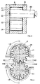
- Fig. 2 shows a gear pump according to the invention, the a housing G, a housing cover D and two interlocking gears Z1 and Z2, with
- the first gear Z1 on a shaft AW installed or forms a pump component with it.
- the shaft AW and thus the gear Z1 are with the help a motor (not shown) driven.
- the second gear Z2 by the first driven.
- the first Z1 and the second gear Z2 each are powered by a separate motor.
- Fig. 3 is a gear pump with one three-part pump housing shown, which is the Housing G accommodating gears Z1 and Z2 on each end is provided with a lid D1 or D2.
- FIG. 4 shows a partial cross section according to FIG Section plane A-A through that shown in Fig. 2 Gear pump according to the invention.
- Inlet and outlet openings EO and AO for the Fluid FM the gears Z1 and Z2 with their ZK tooth tips and partially the housing G Gear pump according to the invention can be seen.
- Due the force distribution in the steady operating state of the Gear pump is one especially in load ranges LB.
- Adequate lubrication is required as these Load ranges LB corresponding forces from the housing G must be included.
- an entry and a Outlet bore for the medium FM are provided, which are substantially perpendicular to the longitudinal axes of the Gears Z1 and Z2 stand.
- Conceivable and also advantageous compared to the variant mentioned above is a Embodiment in which two or more entry and / or Outlet openings for the medium FM are provided, because in such an embodiment there is Possibility that the tooth heads ZK also in the area of Support inlet and outlet openings.
- This Embodiment has the particular advantage that the edges of the inlet opening are relieved.
- the entry and / or exit opening or the associated inlet and outlet bore run essentially in this embodiment parallel to the gear axles.
- FIGS. 5A and 5B a gear wheel is excerpted 5A, a known - provided that that slide bearings are provided for the shafts - and Fig. 5B shows an embodiment according to the invention in a section Show perpendicular to the gear axis MA.
- Fig. 5B shows an embodiment according to the invention in a section Show perpendicular to the gear axis MA.
- As is well known become conventional bearings in conventional gear pumps used to hold the gears in place. This takes place in the gear pumps according to the invention Position as mentioned by the tooth heads ZK slide on the inside of the housing bore.
- Tooth width KD to increase the sliding surface per Tooth tip can be increased.
- Figure 5B Correspondingly trained in this way Gear pumps with a higher required pressure difference insert between suction and pressure side. Will also be used for the tooth heads ZK or by positioning claimed housing parts used a material that is extremely resilient trained gear pumps by a large Area of application.
Landscapes
- Engineering & Computer Science (AREA)
- Mechanical Engineering (AREA)
- General Engineering & Computer Science (AREA)
- Rotary Pumps (AREA)
- Details And Applications Of Rotary Liquid Pumps (AREA)
Priority Applications (2)
| Application Number | Priority Date | Filing Date | Title |
|---|---|---|---|
| DE59711969T DE59711969D1 (de) | 1997-12-23 | 1997-12-23 | Verfahren zur Wellenpositionierung und eine Zahnradpumpe |
| EP19970122713 EP0833056B1 (fr) | 1997-12-23 | 1997-12-23 | Procédé pour le positionnement d'arbre et pompe à engrenages |
Applications Claiming Priority (1)
| Application Number | Priority Date | Filing Date | Title |
|---|---|---|---|
| EP19970122713 EP0833056B1 (fr) | 1997-12-23 | 1997-12-23 | Procédé pour le positionnement d'arbre et pompe à engrenages |
Publications (3)
| Publication Number | Publication Date |
|---|---|
| EP0833056A2 true EP0833056A2 (fr) | 1998-04-01 |
| EP0833056A3 EP0833056A3 (fr) | 1998-07-15 |
| EP0833056B1 EP0833056B1 (fr) | 2004-09-29 |
Family
ID=8227861
Family Applications (1)
| Application Number | Title | Priority Date | Filing Date |
|---|---|---|---|
| EP19970122713 Expired - Lifetime EP0833056B1 (fr) | 1997-12-23 | 1997-12-23 | Procédé pour le positionnement d'arbre et pompe à engrenages |
Country Status (2)
| Country | Link |
|---|---|
| EP (1) | EP0833056B1 (fr) |
| DE (1) | DE59711969D1 (fr) |
Citations (1)
| Publication number | Priority date | Publication date | Assignee | Title |
|---|---|---|---|---|
| EP0753678A2 (fr) | 1996-07-17 | 1997-01-15 | Maag Pump Systems AG | Palier à contact lisse pour un arbre |
Family Cites Families (6)
| Publication number | Priority date | Publication date | Assignee | Title |
|---|---|---|---|---|
| DE323573C (de) * | 1918-04-23 | 1920-07-31 | Fried Krupp Akt Ges | Zahnradpumpe fuer hohe Drehzahlen |
| US2626570A (en) * | 1947-06-13 | 1953-01-27 | Euclid Road Machinery Co | Floating gear pump |
| US3286643A (en) * | 1963-10-14 | 1966-11-22 | Dowty Technical Dev Ltd | Gear pumps and motors |
| FR2163935A5 (fr) * | 1971-12-07 | 1973-07-27 | Rhone Poulenc Sa | |
| US4386893A (en) * | 1981-05-04 | 1983-06-07 | Deere & Company | Gear pump or motor with a shaftless gear |
| DE3312868C2 (de) * | 1983-04-09 | 1986-03-20 | Glyco-Antriebstechnik Gmbh, 6200 Wiesbaden | Hydropumpe |
-
1997
- 1997-12-23 DE DE59711969T patent/DE59711969D1/de not_active Expired - Fee Related
- 1997-12-23 EP EP19970122713 patent/EP0833056B1/fr not_active Expired - Lifetime
Patent Citations (1)
| Publication number | Priority date | Publication date | Assignee | Title |
|---|---|---|---|---|
| EP0753678A2 (fr) | 1996-07-17 | 1997-01-15 | Maag Pump Systems AG | Palier à contact lisse pour un arbre |
Also Published As
| Publication number | Publication date |
|---|---|
| EP0833056B1 (fr) | 2004-09-29 |
| DE59711969D1 (de) | 2004-11-04 |
| EP0833056A3 (fr) | 1998-07-15 |
Similar Documents
| Publication | Publication Date | Title |
|---|---|---|
| EP0753678B1 (fr) | Palier à contact lisse pour un arbre | |
| DE3326910A1 (de) | Oelfreier rotationsverdraengungskompressor | |
| EP0062098A2 (fr) | Turbine hydraulique | |
| DE10239558B4 (de) | Außenzahnradpumpe mit Druckfluidvorladung | |
| DE2825616A1 (de) | Zahnradpumpe | |
| DE1806149A1 (de) | Dichtung an Zahnradpumpen | |
| EP0280093B1 (fr) | Dispositif de lubrification de transmission différentielle pour véhicules automobiles | |
| DE2014892C3 (de) | Hydrodynamisches Radialgleitlager | |
| EP1219841B1 (fr) | Palier lisse,notamment pour une pompe à engrenages | |
| EP1026399A1 (fr) | Vis transporteuses jumelées | |
| DE2536189A1 (de) | Vorrichtung zur einstellung des dynamischen axialen gegenstromschubes bei schraubenpumpen | |
| EP1073845B1 (fr) | Machine volumetrique | |
| DE69716552T2 (de) | Dichtung/lagervorrichtung | |
| DE2048301A1 (de) | Meß- und Spulolpumpe | |
| DE1653810C3 (de) | Zahnradpumpe | |
| DE102012206699A1 (de) | Zahnradmaschine mit wannenartiger Vertiefung an der Außenoberfläche des Gehäuses | |
| EP0833056B1 (fr) | Procédé pour le positionnement d'arbre et pompe à engrenages | |
| DE3045192C2 (de) | Zahnradpumpe | |
| DE19502173C2 (de) | Schraubenpumpe für drehrichtungsunabhängigen Betrieb | |
| DE2927828A1 (de) | Zahnradpumpe bzw. -motor | |
| WO1998021479A1 (fr) | Pompe a engrenages a denture interieure avec entrainement par l'intermediaire de la couronne de train planetaire | |
| DE102006049663A1 (de) | Schraubenspindelpumpe mit Scheibenpumpen-Axiallager | |
| DE2718138A1 (de) | Hydraulische maschine | |
| EP0878625B1 (fr) | Procédé et dispositif pour rendre étanche un arbre ainsi que l'utilisation de ce procédé et de ce dispositif dans une pompe à engrenages | |
| EP0841482B1 (fr) | Pompe rotative |
Legal Events
| Date | Code | Title | Description |
|---|---|---|---|
| PUAI | Public reference made under article 153(3) epc to a published international application that has entered the european phase |
Free format text: ORIGINAL CODE: 0009012 |
|
| AK | Designated contracting states |
Kind code of ref document: A2 Designated state(s): CH DE IT LI |
|
| AX | Request for extension of the european patent |
Free format text: AL;LT;LV;MK;RO;SI |
|
| PUAL | Search report despatched |
Free format text: ORIGINAL CODE: 0009013 |
|
| AK | Designated contracting states |
Kind code of ref document: A3 Designated state(s): AT BE CH DE DK ES FI FR GB GR IE IT LI LU MC NL PT SE |
|
| AX | Request for extension of the european patent |
Free format text: AL;LT;LV;MK;RO;SI |
|
| 17P | Request for examination filed |
Effective date: 19981214 |
|
| AKX | Designation fees paid |
Free format text: CH DE IT LI |
|
| RBV | Designated contracting states (corrected) |
Designated state(s): CH DE IT LI |
|
| 17Q | First examination report despatched |
Effective date: 20010706 |
|
| GRAP | Despatch of communication of intention to grant a patent |
Free format text: ORIGINAL CODE: EPIDOSNIGR1 |
|
| GRAS | Grant fee paid |
Free format text: ORIGINAL CODE: EPIDOSNIGR3 |
|
| GRAA | (expected) grant |
Free format text: ORIGINAL CODE: 0009210 |
|
| AK | Designated contracting states |
Kind code of ref document: B1 Designated state(s): CH DE IT LI |
|
| PG25 | Lapsed in a contracting state [announced via postgrant information from national office to epo] |
Ref country code: IT Free format text: LAPSE BECAUSE OF FAILURE TO SUBMIT A TRANSLATION OF THE DESCRIPTION OR TO PAY THE FEE WITHIN THE PRESCRIBED TIME-LIMIT;WARNING: LAPSES OF ITALIAN PATENTS WITH EFFECTIVE DATE BEFORE 2007 MAY HAVE OCCURRED AT ANY TIME BEFORE 2007. THE CORRECT EFFECTIVE DATE MAY BE DIFFERENT FROM THE ONE RECORDED. Effective date: 20040929 |
|
| REG | Reference to a national code |
Ref country code: CH Ref legal event code: EP |
|
| REG | Reference to a national code |
Ref country code: CH Ref legal event code: NV Representative=s name: TROESCH SCHEIDEGGER WERNER AG |
|
| REF | Corresponds to: |
Ref document number: 59711969 Country of ref document: DE Date of ref document: 20041104 Kind code of ref document: P |
|
| PGFP | Annual fee paid to national office [announced via postgrant information from national office to epo] |
Ref country code: DE Payment date: 20041216 Year of fee payment: 8 |
|
| PGFP | Annual fee paid to national office [announced via postgrant information from national office to epo] |
Ref country code: CH Payment date: 20050222 Year of fee payment: 8 |
|
| PLBE | No opposition filed within time limit |
Free format text: ORIGINAL CODE: 0009261 |
|
| STAA | Information on the status of an ep patent application or granted ep patent |
Free format text: STATUS: NO OPPOSITION FILED WITHIN TIME LIMIT |
|
| 26N | No opposition filed |
Effective date: 20050630 |
|
| PG25 | Lapsed in a contracting state [announced via postgrant information from national office to epo] |
Ref country code: LI Free format text: LAPSE BECAUSE OF NON-PAYMENT OF DUE FEES Effective date: 20051231 Ref country code: CH Free format text: LAPSE BECAUSE OF NON-PAYMENT OF DUE FEES Effective date: 20051231 |
|
| PG25 | Lapsed in a contracting state [announced via postgrant information from national office to epo] |
Ref country code: DE Free format text: LAPSE BECAUSE OF NON-PAYMENT OF DUE FEES Effective date: 20060701 |
|
| REG | Reference to a national code |
Ref country code: CH Ref legal event code: PL |