EP0833064A2 - Assemblage pour des éléments allongés - Google Patents
Assemblage pour des éléments allongés Download PDFInfo
- Publication number
- EP0833064A2 EP0833064A2 EP97113175A EP97113175A EP0833064A2 EP 0833064 A2 EP0833064 A2 EP 0833064A2 EP 97113175 A EP97113175 A EP 97113175A EP 97113175 A EP97113175 A EP 97113175A EP 0833064 A2 EP0833064 A2 EP 0833064A2
- Authority
- EP
- European Patent Office
- Prior art keywords
- clamping
- holding
- connecting body
- section
- connecting device
- Prior art date
- Legal status (The legal status is an assumption and is not a legal conclusion. Google has not performed a legal analysis and makes no representation as to the accuracy of the status listed.)
- Granted
Links
- 239000000463 material Substances 0.000 claims description 9
- 230000000295 complement effect Effects 0.000 claims description 8
- 230000007704 transition Effects 0.000 claims description 5
- 230000013011 mating Effects 0.000 claims description 3
- 230000005489 elastic deformation Effects 0.000 claims 1
- 238000010276 construction Methods 0.000 description 10
- 238000013461 design Methods 0.000 description 6
- 238000005192 partition Methods 0.000 description 5
- 238000004519 manufacturing process Methods 0.000 description 4
- 230000000087 stabilizing effect Effects 0.000 description 3
- 238000003780 insertion Methods 0.000 description 2
- 230000037431 insertion Effects 0.000 description 2
- 230000000149 penetrating effect Effects 0.000 description 2
- 230000009467 reduction Effects 0.000 description 2
- 230000009286 beneficial effect Effects 0.000 description 1
- 230000015572 biosynthetic process Effects 0.000 description 1
- 230000008878 coupling Effects 0.000 description 1
- 238000010168 coupling process Methods 0.000 description 1
- 238000005859 coupling reaction Methods 0.000 description 1
- 230000003247 decreasing effect Effects 0.000 description 1
- 238000011161 development Methods 0.000 description 1
- 230000018109 developmental process Effects 0.000 description 1
- 230000000694 effects Effects 0.000 description 1
- 238000001746 injection moulding Methods 0.000 description 1
- 239000002184 metal Substances 0.000 description 1
- 230000002093 peripheral effect Effects 0.000 description 1
- 238000000926 separation method Methods 0.000 description 1
- 239000011343 solid material Substances 0.000 description 1
- 230000006641 stabilisation Effects 0.000 description 1
- 238000011105 stabilization Methods 0.000 description 1
- 238000012549 training Methods 0.000 description 1
- 238000012546 transfer Methods 0.000 description 1
Images



Classifications
-
- F—MECHANICAL ENGINEERING; LIGHTING; HEATING; WEAPONS; BLASTING
- F16—ENGINEERING ELEMENTS AND UNITS; GENERAL MEASURES FOR PRODUCING AND MAINTAINING EFFECTIVE FUNCTIONING OF MACHINES OR INSTALLATIONS; THERMAL INSULATION IN GENERAL
- F16B—DEVICES FOR FASTENING OR SECURING CONSTRUCTIONAL ELEMENTS OR MACHINE PARTS TOGETHER, e.g. NAILS, BOLTS, CIRCLIPS, CLAMPS, CLIPS OR WEDGES; JOINTS OR JOINTING
- F16B12/00—Jointing of furniture or the like, e.g. hidden from exterior
- F16B12/44—Leg joints; Corner joints
- F16B12/50—Metal corner connections
-
- A—HUMAN NECESSITIES
- A47—FURNITURE; DOMESTIC ARTICLES OR APPLIANCES; COFFEE MILLS; SPICE MILLS; SUCTION CLEANERS IN GENERAL
- A47B—TABLES; DESKS; OFFICE FURNITURE; CABINETS; DRAWERS; GENERAL DETAILS OF FURNITURE
- A47B47/00—Cabinets, racks or shelf units, characterised by features related to dismountability or building-up from elements
- A47B47/0016—Node corner connectors, e.g. cubic
-
- E—FIXED CONSTRUCTIONS
- E04—BUILDING
- E04B—GENERAL BUILDING CONSTRUCTIONS; WALLS, e.g. PARTITIONS; ROOFS; FLOORS; CEILINGS; INSULATION OR OTHER PROTECTION OF BUILDINGS
- E04B1/00—Constructions in general; Structures which are not restricted either to walls, e.g. partitions, or floors or ceilings or roofs
- E04B1/38—Connections for building structures in general
- E04B1/58—Connections for building structures in general of bar-shaped building elements
- E04B1/5825—Connections for building structures in general of bar-shaped building elements with a closed cross-section
- E04B1/5831—Connections for building structures in general of bar-shaped building elements with a closed cross-section of substantially rectangular form
-
- F—MECHANICAL ENGINEERING; LIGHTING; HEATING; WEAPONS; BLASTING
- F16—ENGINEERING ELEMENTS AND UNITS; GENERAL MEASURES FOR PRODUCING AND MAINTAINING EFFECTIVE FUNCTIONING OF MACHINES OR INSTALLATIONS; THERMAL INSULATION IN GENERAL
- F16M—FRAMES, CASINGS OR BEDS OF ENGINES, MACHINES OR APPARATUS, NOT SPECIFIC TO ENGINES, MACHINES OR APPARATUS PROVIDED FOR ELSEWHERE; STANDS; SUPPORTS
- F16M5/00—Engine beds, i.e. means for supporting engines or machines on foundations
-
- A—HUMAN NECESSITIES
- A47—FURNITURE; DOMESTIC ARTICLES OR APPLIANCES; COFFEE MILLS; SPICE MILLS; SUCTION CLEANERS IN GENERAL
- A47B—TABLES; DESKS; OFFICE FURNITURE; CABINETS; DRAWERS; GENERAL DETAILS OF FURNITURE
- A47B2230/00—Furniture jointing; Furniture with such jointing
- A47B2230/14—Furniture connections by means of two half-shells
-
- E—FIXED CONSTRUCTIONS
- E04—BUILDING
- E04B—GENERAL BUILDING CONSTRUCTIONS; WALLS, e.g. PARTITIONS; ROOFS; FLOORS; CEILINGS; INSULATION OR OTHER PROTECTION OF BUILDINGS
- E04B1/00—Constructions in general; Structures which are not restricted either to walls, e.g. partitions, or floors or ceilings or roofs
- E04B1/38—Connections for building structures in general
- E04B1/388—Separate connecting elements
- E04B2001/389—Brackets
-
- E—FIXED CONSTRUCTIONS
- E04—BUILDING
- E04B—GENERAL BUILDING CONSTRUCTIONS; WALLS, e.g. PARTITIONS; ROOFS; FLOORS; CEILINGS; INSULATION OR OTHER PROTECTION OF BUILDINGS
- E04B1/00—Constructions in general; Structures which are not restricted either to walls, e.g. partitions, or floors or ceilings or roofs
- E04B1/38—Connections for building structures in general
- E04B1/58—Connections for building structures in general of bar-shaped building elements
- E04B2001/5875—Connections for building structures in general of bar-shaped building elements using exterior clamping plates or shells
-
- E—FIXED CONSTRUCTIONS
- E04—BUILDING
- E04B—GENERAL BUILDING CONSTRUCTIONS; WALLS, e.g. PARTITIONS; ROOFS; FLOORS; CEILINGS; INSULATION OR OTHER PROTECTION OF BUILDINGS
- E04B1/00—Constructions in general; Structures which are not restricted either to walls, e.g. partitions, or floors or ceilings or roofs
- E04B1/38—Connections for building structures in general
- E04B1/58—Connections for building structures in general of bar-shaped building elements
- E04B2001/5881—Connections for building structures in general of bar-shaped building elements using an undercut groove, e.g. dovetail groove
-
- E—FIXED CONSTRUCTIONS
- E04—BUILDING
- E04B—GENERAL BUILDING CONSTRUCTIONS; WALLS, e.g. PARTITIONS; ROOFS; FLOORS; CEILINGS; INSULATION OR OTHER PROTECTION OF BUILDINGS
- E04B1/00—Constructions in general; Structures which are not restricted either to walls, e.g. partitions, or floors or ceilings or roofs
- E04B1/38—Connections for building structures in general
- E04B1/58—Connections for building structures in general of bar-shaped building elements
- E04B2001/5887—Connections for building structures in general of bar-shaped building elements using connectors with sockets
Definitions
- the invention relates to a connecting device for longitudinal elements, with at least one connecting body, the at least two stop shots pointing in different directions has, each for receiving a length section one to be clamped to the connecting body by means of a clamping device Longitudinal elements are suitable.
- connection device goes out, for example of DE 89 12 365 U1. It is used for longitudinal elements such as square tubes or other profile bars interconnect to create frames, frames, shelves or build other constructions.
- connecting bodies present, which are the nodes of each other represent connected longitudinal elements.
- the longitudinal elements are for mutual connection with their respective facing End in holding receptacles provided for this purpose on the connecting body plugged in.
- tensioning devices provided on the connecting body the longitudinal elements on their in the connecting body located length section with the connecting body tense.
- the tensioning devices are by pressure grub screws formed, the longitudinal element from one side against the Press the opposite wall that limits the holding fixture.
- the longitudinal elements in the holding receptacles of the connecting body To be able to insert them, they must be movable in the axial direction be.
- the mobility in the axial direction is at Construction of self-contained frames, frames or the like however often restricted or not available.
- the longitudinal elements by the pressure grub screw from the side of which is selectively loaded. Because the contact area very low between the set screw and the longitudinal element high surface pressure occurs, which leads to damage of the longitudinal elements and with decreasing tension can lead.
- the object of the invention is therefore a connecting device to create the assembly of frames, racks, scaffolding or other constructions composed of longitudinal elements much easier and with excessive material stress of the longitudinal elements as a result of the loading can be avoided by the tensioning devices.
- the connecting body in the range of at least one by at least a separation plane passing through a holding plane into several separate Clamping shells is divided, each with a holding receptacle section the respective, penetrated by the parting plane
- Have stop recording and in pairs by at least a clamping device releasably clamped together are that they are the length sections located in the holding receptacles of the longitudinal elements with their holder sections press and hold tight.
- the longitudinal elements By dividing the connecting body into several clamping shells the longitudinal elements can be installed before the connector is installed be brought into their final position.
- the clamping shells of a connecting body can then be of different types Sides on the longitudinal elements to be connected put on and detachable with each other by means of the clamping devices get connected. An insertion and thus a shift the longitudinal elements in the axial direction are not necessary.
- By releasably tightening the clamping shells together at the same time those in the holding shots Length sections of the longitudinal elements through the clamping shells clamped on. The clamping force is even here spread a larger area so that punctual fatigue or Damage to the material can be avoided.
- At least one connecting body is expediently through a parting plane is divided into exactly two clamping shells.
- the Positioning of one with only two clamping shells Connection body is very simple and facilitates assembly essential.
- a connecting body passes through four holding receptacles, which are arranged such that the longitudinal axes Adjacent holding shots in perpendicular to each other and have directions aligned parallel to the parting plane.
- each clamping shell of a connecting body in addition to the on it provided holding receptacle sections in the area of the parting plane at least one complete stop recording arranged.
- the complete holding fixture arranged on a clamping shell perpendicular to the directions of the holding shots that are caused by the Dividing plane are divided.
- corner connections are made in which three longitudinal elements or three pairs of coaxial to each other Longitudinal elements are perpendicular to each other.
- the complete support of the surrounding wall of a connecting body for the clamping application of one in it Length section of a longitudinal element at least one Clamping slot formed, the at least one clamping device is assigned with which its width and thus the cross section the holding fixture for tensioning a longitudinal element lets wrestle.
- This has the same effect as when clamping by means of two separate clamping shells.
- the clamping slot replaces the parting line. This one too Measure is the longitudinal element to be clamped in the holding fixture clamped across its circumference and not selective.
- At least a connecting body contains at least one pair of holding receptacles, which are arranged opposite each other so that their Longitudinal axes coincide.
- the stop shots open inside, so that the connecting body penetrates Continuity results, a longitudinal element can simultaneously go through both holding receptacles and the connecting body can be placed anywhere along a longitudinal element can be scheduled. Appropriately have the stop shots the same cross-section with each other.
- a connecting body be designed as a transition piece and at least two holding receptacles different cross-section included.
- a Connection body can be used, for example, Longitudinal elements of different cross-sections in a common To make the system usable.
- the cross section is at least one and preferably all holding receptacles of a connecting body is rectangular and in particular square.
- this enables the connection of the design of racks, shelves, brackets or other particularly often used square profile elements or - pipes.
- the tensioning devices are arranged outside the stop shots next to these.
- the tensioning devices do not act directly on the in the longitudinal sections of the longitudinal elements located in the holding receptacles a, but act on it indirectly via that of clamps applied to them.
- At least one tensioning device a connecting body a screw and a complementary Has counter thread.
- a screw with a counter thread represents a very simple and inexpensive way one detachable connection.
- An alternative design provides for the counter thread a screw nut. Also for example from Plastic material existing clamping shells can thereby high thread strength can be achieved by using metal nuts used.
- a connector body in the area of its preferably single parting plane has a circular outline.
- the clamping shells can each face away from the joining surface Outer surface in particular flat and parallel to Parting plane should be flattened, especially if the connecting body only for making two-dimensional connections should serve. If three-dimensional connections are also desired, a hemispherical connector is recommended for a two-part connector Formation of a respective clamping shell, so that the Connection body in the state of use essentially the shape can have a bullet.
- an adapter part which clamps of a cylindrical part in a rectangular cross section having a holding body of a connecting body, wherein there is one to be arranged in the aforementioned holding fixture, radially deformable clamping section with a cross section the outer contour adapted to the holding fixture and a clamping fixture defining cylindrical inner contour for inclusion of the cylindrical part to be clamped.
- Such one Adapter part enables the tensioning of longitudinal elements with circular cross section by means of connecting bodies, the holding receptacles have a rectangular or square cross section. The manufacture of another type of connector body with round holding fixtures can thus be omitted.
- the clamping section in several longitudinal, radially movable to each other and spaced in the circumferential direction of the clamping receptacle Clamping elements divided.
- the individual clamping elements are radially on top of each other due to a respective clamping shell moves and thus transmit the clamping force to that in the Cylindrical part.
- a rotating piece is present the one cylindrical first fixable in the clamp Fastening section and in a fixed state second fastening section protruding from the clamping receptacle for fastening at least one further component.
- the rotating piece is with its cylindrical first fastening section fixed in the clamping receptacle of the adapter part.
- the rotating piece can be rotated in any direction about its longitudinal axis Angle can be positioned rotated in the clamp receptacle. All on the second mounting section of the rotating piece attached other components can be in a desired angular alignment to be attached to the connector body.
- the second fastening section is expediently one Swivel piece formed cuboid.
- a C-shaped, in particular can be fixed on the second fastening section of the rotary piece
- Groove rail can be provided in the with a receptacle for fasteners provided sliding blocks can be provided for the attachment of other components are.
- a longitudinal element serving plate connector be that by means of a clamping device on a longitudinal part can be fixed, the tensioning device being attached at the same time of the plate connecting part to the plate-like body serves.
- a plate connector serves to plate-like Covers on frames formed from longitudinal elements, To attach shelves or the like.
- the panel connector is braced with the respective longitudinal element and can be positioned on the longitudinal element before bracing can be pushed back and forth as desired.
- connecting body made of plastic are made. Due to the lower weight of plastic bodies are lightweight and, under certain circumstances, portable constructions realizable.
- any constructions such as shelves or frames, Frames and holders for tables, machines or vehicles, and much more to be built.
- Another application exists for example in the construction of shelves in the area of warehousing.
- the struts of such constructions often consist of rod, rod or tube-like longitudinal elements 1.
- the longitudinal elements 1 are connecting bodies 2 of the connecting device according to the invention can be used.
- the connecting body 2 form at the designated locations one-, two- or three-dimensional connection nodes which the longitudinal elements 1 protrude in different directions.
- Clamping devices 3 are provided. They create a clamping force the longitudinal elements 1 in their desired, predetermined Holds position on the associated connector body 2.
- Each connecting body 2 has at least two in different Direction-pointing, each to accommodate a length section a longitudinal element 1 suitable holding receptacles 4.
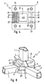
- the connecting body 2 In contains the embodiments of Figures 1, 2 and 5 the connecting body 2 four holding receptacles 4. Not every holding receptacle 4 must be in the position of use of the connecting body 2 Longitudinal element 1 included.
- the connecting body 2 is through at least one parting plane 7 divided into several clamping shells 8.
- the clamping shells 8 can consist of solid material. You're over the tensioners 3 can be releasably braced against one another transversely to the parting plane, that they are in the area of the holding receptacles 4 on longitudinal sections 5 of the longitudinal elements 1 rest and are pressed firmly against them. Thus, through the releasable connection of the clamping shells 8 at the same time a bracing of those located in the connecting body 2 Length sections 5 of the longitudinal elements 1 reached.
- all holding receptacles 4 have a connecting body 2 the same cross section.
- the cross section of the holding receptacle 4 is in all Embodiments rectangular, preferably square.
- parting plane 7 of a respective connecting body 2 by at least one and preferably by several holding receptacles 4 passes through these are also from the parting plane 7th enforced holding receptacles 4 divided in the longitudinal direction, and in a number corresponding to the number of clamping shells 8 of holding receptacle sections 4 '. These are for parting line 7 open towards. Are the clamping shells 8 in the area of the parting plane 7 put together, the mutually assigned complement each other Stop receptacle sections 4 'for the respective stop receptacle 4.
- the embodiments of the connecting body 2 according to the figures 1 to 7 all have at least one pair of holding receptacles 4 on whose longitudinal axes 6 coincide.
- Have the two Holding receptacles 4 have an identical cross section, so a Longitudinal element 1 with a corresponding design of the clamping shells 8 go through both holding receptacles 4.
- a respective connecting body 2 contains two of these Hold pairs.
- the two here in pairs coaxially one after the other Arranged holding receptacles 4 are not only for Outer surface of the connecting body 2, but also on the axially facing inner sides 12 open.
- This connecting body 2 is for receiving Longitudinal elements 1 with a different cross-section than Transition piece 9 is formed. It serves as a coupling link, if two different thickness or different cross-sectional shape having longitudinal elements 1 just connected to each other Need to become.
- Form transition piece 9 as an angle connector, at which the longitudinal axes of the holding receptacles 4 at an angle to each other are aligned.
- the connecting body 2 in exactly two Clamping shells 8.
- This parting plane 7 passes through four in this or holding receptacles 4 in aligned parallel to this plane Longitudinal direction. Adjacent holding receptacles divided by the parting plane 7 4 each point perpendicular to one another Directions. In this special case, the axes fall opposite one another arranged holding shots 4 on top of each other, so that the holding fixtures form a flat cross.
- a respective one Clamping shell 8 contains half of those divided by the parting plane 7 Stop recording 4.
- the holding receptacle 4 is made up of two on one of each Clamping shells 8 located holding receptacle sections 4 'or half-shell-shaped halves 10 of a holding receptacle 4 together.
- the embodiments according to FIG. 5 have and 6 in the area of the parting plane 7 a circle-like outline.
- the circular line is in the area of the mouths of the stop shots 4 slightly flattened.
- the connector body 2 a spherical shape, each of the two existing clamping shells 8 shaped like a hemisphere is.
- the clamping shells 8 of the embodiment according to FIG. 5 each have the shape of a hemisphere, from which the Partition plane 7 opposite outer surface a spherical cap Section is removed. The remaining peripheral area is therefore slightly conical.
- a respective holding receptacle 4 is based on its longitudinal axis 6, surrounded or defined on the circumferential side by a holding wall 11.
- the inner contour of a respective holding receptacle 4 is preferred at least essentially complementary to the outer contour of the longitudinal section 5 of the longitudinal element to be clamped 1 formed so that the relevant length section 5 in tension Condition of the retaining wall 11 is closely enclosed.
- the area of the parting plane 7 can, however, be more or less large gap 19 are present.
- the connecting bodies 2 of FIGS. 3, 4 and 6 on at least one clamping shell 8 additionally via an im substantially perpendicular to the parting plane 7 and through this Partition plane 7 divided holding receptacles 4 standing complete Stop 13.
- the complete stop 13 is on one arranged single clamping shell 8 and not by one Dividing level 7 divided. According to Figure 3, one of the clamping shells 8 about a full stop 13 while the other clamping shell 8 closed on the corresponding side is.
- each complete holding receptacle 13 has both Clamping shells 8 each have a complete holding receptacle 13
- Longitudinal axis 6 'of each complete holding receptacle 13 is preferably perpendicular to the longitudinal axes 6 in the parting plane 7 lying holding receptacles 4, preferably all Intersect axes at a common point. That is called complete holding receptacle 13 is the outer contour of the Clamping shell 8 in particular arranged in the middle.
- At least one clamping slot 15 is introduced, which is used for holding 13 is open and to allow tightening that can be determined in the complete holding receptacle 13 Longitudinal element 1 is used.
- two clamping slots 15 are provided, the are expediently arranged such that they are on opposite Sides of the complete holding fixture 13 across are opposite to the longitudinal axis and the wall 14 partially split.
- the two clamping slots 15 run in the longitudinal direction the complete holding receptacle 13, the wall 14 and thus the relevant clamping shell 8 expediently not enforce completely in the longitudinal direction 6, but on the Partition plane 7 facing inner opening 20 of the complete Holding receptacle 13 are a stabilizing piece 16 to let.
- the stabilizing piece 16 serves the stability of the Clamping shell 8 and depending on the selected material and dimension the clamping shell is also omitted if the stability of the Clamping shell 8 would still be guaranteed, for example, by the clamping slots as in Figures 3 and 4 on the holding receptacle 13 opposite side within the clamping shell 8 ends.
- a respective clamping slot 15 thus extends in the embodiment starting from which the outer opening of the complete holding receptacle 13 surrounding edge area 66 of the Outer surface of the clamping shell 8 in the longitudinal direction 6 of this holding receptacle 13, it facing the parting plane 7 inner opening of the holding receptacle 13 ends. So he's on one axial side open to the outer surface 68 of the clamping shell 8, while being closed on the opposite axial side is. Its expansion transverse to the longitudinal axis of the holding receptacle 13 is dimensioned so that the parts of the clamping shell divided by him 67, 67 'have sufficient flexibility to attack one at right angles to the direction of expansion of the clamping slot 15 forces acting on them are moved towards each other can.
- Holding receptacle 13 measured length of the respective clamping slot dimensioned so that it is provided on the clamping shell before reaching Stop receiving sections 4 'ends.
- Each clamping slot 15 is expediently from a clamping device receptacle 21 interspersed such that the in use position Clamping device located in the clamping device receptacle 21 3 also the clamping slot 15 transversely to its plane of expansion enforced and able to operate Width of the clamping slot 15 by deformation of the clamping shell parts 67, 67 'to reduce. From Figure 4 it can be seen that the clamping device receptacles 21 in particular perpendicular to one each clamping slot 15 run.
- the cross-sectional shape of the complete holding receptacle 13 suitably corresponds to that through a parting plane 7 divided holding fixtures 4.
- Clamping device receptacles 21 are provided for bracing the clamping shells 8 together. This are arranged outside the holding receptacles 4 next to them, that the clamping devices 3 are not through the holding receptacles 4 go through.
- the clamping devices 3 are preferably made of a screw 22 and a complementary mating thread 23 are formed. By doing 1 are the mating thread 23 of a respective clamping device 3 in one piece a clamping shell 8 attached.
- the counter thread 23 is included as an internal thread in a respective fixture holder 21 realized. In this case, only one of the clamping shells 8 of the connecting body has 2 the counter thread 23.
- the one in each another clamp 8 section of a jig receptacle serves to receive the screw 22 and is trained threadless.
- a connecting body 2 can be introduced into a clamping shell 8 Internal thread may not be sufficiently stable to the necessary To generate clamping forces of a respective clamping device 3. Then there is the alternative to a screw nut 24 to use as counter thread 23.
- the clamping device receptacles 21 are, for example, on their ends assigned to two different clamping shells 8 Extensions 27 provided to countersink the screw heads or the existing nut 24.
- the extensions are dimensioned so that neither Screw 22, and any existing nut 24 protrude from the connecting body 2 in the position of use.
- the nut 24 in the hexagon recess 28 engage and is thus when turning the associated screw 22 secured against rotation.
- the complementary to the outer contour the nut 24 designed inner contour of the recess 28 is shaped so that the nut with at least slight press fit is held in it. That way gets besides the anti-rotation lock also a loss protection for the nuts 24.
- all extensions 27 are in the form of a hexagon recess 28 designed so that a directional Assembly of a respective clamping device 3 is possible.
- the one at the bottom has Clamping shell 8 exclusively via holding receptacle sections 4 'and has no additional full stop 13. It can therefore be carried out with an extremely low overall height be, the opposite of the joining surface 26
- the outer surface is preferably flattened and completely closed is.
- it has an additional complete Holding receptacle 13 provided other clamping shell 8 at a right angle to the joining surface 26 a greater overall height by which additional complete holding receptacle 13 with sufficient to be able to train large lengths.
- no constant overall height is provided, rather the clamping shell 8 on the outside of the joining surface 26 ' graduated.
- the clamping shell 8 has a central, the holding receptacle here 13 and the clamping slots 15 containing rib-like Elevation 30 on both sides of a step-like recess 31 is flanked. At these recesses 31 open Clamping device receptacles 21 of both the clamping slots 15 and the clamping devices assigned to the two clamping shells 8 3 out. This ensures that the clamping devices 3 are easily accessible.
- two clamping devices 3 are each one common depression 77 forth accessible and protected there housed.
- the edges 66 of the mouths surrounding the holding receptacles 4 due to the essentially cube or cuboid shape automatically executed as plan areas.
- Such flat surfaces may be useful for certain purposes.
- Around corresponding also in the exemplary embodiments according to FIGS. 5 and 6 To get flat surfaces there is the outer surface 68 of the respective connecting body 2 on the edge region 66 flattened, which is why there is no longer an exact spherical shape.
- Wheels of attached attachments run off.
- connection device In order to make the use of a connecting body 2 more flexible, also sees the connection device according to the example Adapter parts 32 before that for clamping any cylindrical Part in a with rectangular holding receptacles 4 provided connecting body 2 can serve.
- the adapter part 32 has an elongated clamping section 38 with a cylindrical, the adapter part completely along its longitudinal axis penetrating opening on which a clamping receptacle 33 limited.
- a cylindrical part 41 to be clamped becomes clamped in the clamping receptacle 33 of the adapter part 32.
- the adapter part 32 with its clamping section 38 the Outer contour adapted to the inner contour of the holding receptacle 4 is inserted into the holding receptacle 4, the one to be clamped cylindrical part 41 in turn already in the clamping receptacle 33 can be inserted or subsequently inserted into this becomes. Then the clamping section 38 with transverse forces applied so that it deforms in the radial direction and in turn applied to the cylindrical part 41 and this holds tight.
- the clamping forces are preferably from the Clamping devices 3 of a connecting body 2 are produced and by means of the walls 11, 14 of the relevant holding receptacle 4 transfer the inserted adapter part 32.
- the adapter part 32 shown in Figure 2 is in the range of Clamping receptacle 33 by introduced along its longitudinal direction slot-like spaces 34 in several clamping elements 35 structured.
- the clamping elements 35 are in the circumferential direction spaced by the spaces 34. Extend according to example the spaces 34 over the length of the clamping section 38, to which an annular connecting piece 36 connects, with which the clamping elements 35 preferably in one piece are connected.
- the connecting piece 36 can be designed in this way be that it is at least in the use position of the adapter part 32 is partially outside the holding receptacle 4 and a stop 37 forms the one in the use position outside in the area Holding receptacle 4 rests on at least one clamping body 8 thereby the position of the adapter part 32 in the position of use define and limit the insertion depth.
- any angular positions When building by means of the connecting device Constructions it may be desirable to use any angular positions to be able to pretend. In particular, you should first Unknown angles can be adjustable, which is the case, for example the adjustment of measuring devices such as sensors may be necessary can.
- one is from a cylindrical first Attachment portion 41 and a second attachment portion 42 formed rotary piece 43 is provided. This is about the cylindrical first fastening section 41 in the Clamping receptacle 33 of the adapter part 32 can be fixed, the second fastening section protrudes from the clamping receptacle 33.
- the rotating piece 43 can be in any position around the longitudinal axis of the cylindrical first mounting portion 41 rotated Position in the clamp receptacle 33 are positioned.
- FIG. 2 has for attaching a another component has an internal thread 44 for fasteners 46.
- a fastener 46 in the form of a Engage screw.
- a any other fastening device 49 may be provided.
- the design of the second fastening section 42 is in principle any. This can vary depending on the application Take shape. In the variant according to Figure 2 is cuboid.
- a grooved rail 47 suitable. In the exemplary embodiment according to FIG. 2, this indicates C-shaped profile.
- this grooved rail 47 there are sliding blocks 48 along the longitudinal axis of the grooved rail 47 for attachment other components slidably and fixable.
- the sliding blocks 48 have fastening devices for this 49 on.
- the grooved rail 47 contains on one of its long sides a slot opening 50.
- the sliding blocks guided in the slot rail 47 48 are on this side by protruding sections 53 overlapped the rail wall 54 such that the protruding sections 53 between the sliding block 48 and one attached to it additional component 55 can be clamped. Because of this Clamping defines the position of the component. Depending on Length of the groove rail 47 can be any number of other components be attached.
- a section provided with a right-angled section Angle piece is an example of another component 55, the is connected to the sliding block 48 and the attachment of a Sensor element 56 is used.
- the sliding block 48 can along the Longitudinal axis of the groove rail 47 shifted and thus the position of the sensor element 56 can be varied.
- the groove rail can, for example, directly in a holding fixture 4 of a connecting body 2 can be fixed or else via a second designed according to a sliding block Fastening section 42 to be attached to a rotating piece 43. About this rotary piece 43 and a possibly existing adapter part 32 is then the grooved rail 47 indirectly with a connecting body 2 connected.
- connection device By using the connection device Housings are constructed or wall elements are required, at least one can be formed by the longitudinal elements 1 Frame area covered by a plate-like body 60 will.
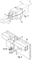
- plate connection parts 61 is provided (FIG. 9), which by means of a tensioning device 62 can be fixed to a longitudinal element 1 and via a fastening device 63 connected to the plate-like body 60 can be.
- the tensioning device 62 simultaneously as a fastening device 63 and is by a screw 64 and a nut 65 formed.
- the plate connector 61 includes one for receiving a clamping opening 69 provided in a longitudinal element 1, which encloses the longitudinal element 1.
- the plate connector 61 expediently U-shaped.
- a first one Leg 70 and a second leg 71 of this U-shaped Plate connector 61 are opposite in the use position and are connected to each of them via a connector 72 Ends connected to one another in the area of the clamping opening 69, so as to form the U-like shape.
- the tensioning device 62 and the fastening device 63 are provided on the two opposite The ends of the legs 70, 71 .
- One of both Legs 70, 71 can be in this area to each other Leg to be continued so that the distance between the two legs 70, 71 reduced in the position of use, respectively not applicable.
- the second leg 71 in the direction of the first leg 70 expanded or hidden.
- a notch 76 around the two legs 70, 71 when clamping the plate connector 61 on a longitudinal element 1 to be able to move closer together.
- the notch 76 enables otherwise also open or swivel the a leg 70 because there is a kind of film hinge. This facilitates the attachment of the plate connector 61 on Longitudinal element.
- connection body can exist as a plastic material.
- Injection molding processes are such complex plastic bodies easy to manufacture and due to its low weight also for portable constructions.
- FIG 2 An embodiment of a connecting body is shown in FIG 2 emerges from two partitions 7 in more than two clamping shells 8 is divided.
- they are two parting planes 7 in FIG. 8 with reference numerals 7 'and 7' ' featured.
- the first parting plane 7 ' corresponds in terms of Design and arrangement of those as in the rest Embodiments is realized.
- the further parting plane 7 ′′ runs at right angles to the first parting plane 7 ′, interspersed the connecting body 2, however, not completely.
- the first parting plane 7 ' Connection body 2 divided into two clamping shells one of the two clamping shells through the further parting plane 7 '' in turn is divided into two clamping shells. Lying that way a total of three clamping shells in the exemplary embodiment, which can be mutually clamped via clamping devices 3.
- the further parting plane 7 ′′ also extends completely through the connecting body 2 so that there are four clamping shells surrender.
- the embodiment described in Figures 1 to 6 with only two clamping shells is much cheaper to implement and also enables easier handling.
Landscapes
- Engineering & Computer Science (AREA)
- General Engineering & Computer Science (AREA)
- Mechanical Engineering (AREA)
- Architecture (AREA)
- Physics & Mathematics (AREA)
- Electromagnetism (AREA)
- Civil Engineering (AREA)
- Structural Engineering (AREA)
- Mutual Connection Of Rods And Tubes (AREA)
- Handcart (AREA)
- Superconductors And Manufacturing Methods Therefor (AREA)
- Coupling Device And Connection With Printed Circuit (AREA)
Applications Claiming Priority (2)
| Application Number | Priority Date | Filing Date | Title |
|---|---|---|---|
| DE29616635U | 1996-09-25 | ||
| DE29616635U DE29616635U1 (de) | 1996-09-25 | 1996-09-25 | Verbindungseinrichtung für Längselemente |
Publications (3)
| Publication Number | Publication Date |
|---|---|
| EP0833064A2 true EP0833064A2 (fr) | 1998-04-01 |
| EP0833064A3 EP0833064A3 (fr) | 1999-03-17 |
| EP0833064B1 EP0833064B1 (fr) | 2002-12-04 |
Family
ID=8029665
Family Applications (1)
| Application Number | Title | Priority Date | Filing Date |
|---|---|---|---|
| EP97113175A Revoked EP0833064B1 (fr) | 1996-09-25 | 1997-07-31 | Assemblage pour des éléments allongés |
Country Status (2)
| Country | Link |
|---|---|
| EP (1) | EP0833064B1 (fr) |
| DE (2) | DE29616635U1 (fr) |
Cited By (4)
| Publication number | Priority date | Publication date | Assignee | Title |
|---|---|---|---|---|
| GB2361504B (en) * | 2000-04-18 | 2003-12-24 | Buro Happold Ltd | A coupling and a method of constructing grid shell buildings using such a coupling |
| WO2004113634A1 (fr) * | 2003-06-06 | 2004-12-29 | Gilbert Ossbahr | Systeme destine a relier des poutres a section transversale carree ou rectangulaire |
| ES2540164A1 (es) * | 2014-01-03 | 2015-07-08 | Universidade De Vigo | Sistema de unión desmontable y reconfigurable para perfiles de tubo cuadrado |
| ES2553339A1 (es) * | 2014-06-05 | 2015-12-07 | Universidade De Vigo | Sistema desmontable para unión continua de perfiles de tubo cuadrado |
Families Citing this family (10)
| Publication number | Priority date | Publication date | Assignee | Title |
|---|---|---|---|---|
| DE29706495U1 (de) * | 1997-04-11 | 1997-07-10 | Festo Kg, 73734 Esslingen | Verbindungskörper zur Verbindung von Längselementen |
| FR2764670B1 (fr) * | 1997-06-16 | 1999-08-20 | Rech Etude Materiel Ind Remi | Dispositif d'assemblage d'elements longitudinaux |
| DE69830150T2 (de) | 1998-06-09 | 2006-02-23 | Husson International S.A. | Verbindungsknoten |
| DE102006028731A1 (de) * | 2006-06-20 | 2007-12-27 | König + Neurath AG | Verbindungsvorrichtung |
| GR1006851B (el) * | 2008-05-16 | 2010-07-06 | Ι. Παλαιοχωρινος Φωτιστικα Α.Β.Ε.Ε., | Ενισχυτικη γωνια συνδεσης πλαισιων |
| DE102014019623B4 (de) * | 2014-12-23 | 2019-01-24 | André Kronberg | Möbelbausystem und Scharnier für Glas und flächige Materialien |
| NL2015682B1 (en) * | 2015-10-29 | 2017-05-31 | The Mastermind Company B V | Coupling device and connecting device. |
| CA2949737C (fr) * | 2016-01-22 | 2017-07-04 | Merchant Ambassador (Holdings) Ltd. | Tables de jeu et dispositifs de coin associes |
| ITUA20162429A1 (it) * | 2016-04-08 | 2017-10-08 | Goppion Spa | Vetrina museale con pianale portante |
| CN109854590B (zh) * | 2018-11-27 | 2024-10-22 | 佛山市爱拼科技有限公司 | 一种连接结构以及采用连接结构的板件组件 |
Citations (1)
| Publication number | Priority date | Publication date | Assignee | Title |
|---|---|---|---|---|
| DE8912365U1 (de) | 1989-10-18 | 1990-11-15 | Dinstühler, Manfred, 5609 Hückeswagen | Rohrmuffenverbinder |
Family Cites Families (25)
| Publication number | Priority date | Publication date | Assignee | Title |
|---|---|---|---|---|
| US1589917A (en) * | 1925-01-20 | 1926-06-22 | Rolland G Williams | Reenforcing clamp for jointed iron poles |
| BE526473A (fr) * | 1953-02-13 | |||
| DE1882176U (de) * | 1963-08-19 | 1963-11-07 | Koemmerling G M B H Geb | Schelle zur befestigung von kunststoffbauplatten. |
| FR1514258A (fr) * | 1967-01-09 | 1968-02-23 | Raccord expansible pour éléments de construction tubulaires | |
| FR2153804A5 (fr) * | 1971-09-24 | 1973-05-04 | Heuliez Henri Sa | |
| FR2250395A5 (en) * | 1973-11-02 | 1975-05-30 | Eclairage Tech | Assembly device for false ceiling framework - three part sphere locks tubes so their axes meet at a point |
| US3900269A (en) * | 1974-11-07 | 1975-08-19 | Midland Ross Corp | Channel joint and joiner therefor |
| FR2404139A1 (fr) * | 1977-09-26 | 1979-04-20 | Clement Louis | Systeme d'assemblage, notamment pour assembler sans soudage des ouvrages de ferronnerie |
| FR2430534A1 (fr) * | 1978-07-06 | 1980-02-01 | Lahaye Claude | Systeme pour l'assemblage d'elements de structure spatiale |
| SE416995B (sv) * | 1979-05-17 | 1981-02-16 | Opto System Ab | Rorkoppling |
| GB2070721B (en) * | 1980-03-03 | 1983-09-14 | Conforti M | Joint member for rods or tubes |
| GB2126276B (en) * | 1982-09-07 | 1985-08-14 | Rediffusion Reditronics Ltd | Cable clamp |
| FR2540577A1 (fr) * | 1983-02-09 | 1984-08-10 | Mati Jean | Moyen de fixation de profiles tubulaires a des parois |
| GB2138195A (en) * | 1983-04-15 | 1984-10-17 | Colin John Stewart Stephenson | A spaceframe for a display |
| GB2159229A (en) * | 1984-05-19 | 1985-11-27 | Arthur Philip Paton | Connecting blocks |
| FR2581717A1 (fr) * | 1985-05-07 | 1986-11-14 | Club Atelier Innovation | Raccord pour l'assemblage angulaire d'organes tubulaires |
| DE8715772U1 (de) * | 1987-11-28 | 1988-03-31 | Berger, Kurt, 41564 Kaarst | Kupplungselement für die Knoten von aus Stäben zusammengesetzten Gitterkonstruktionen |
| GB2224800B (en) * | 1988-11-07 | 1992-12-09 | Tecna Limited | Framework connector assembly |
| DE8905326U1 (de) * | 1989-04-27 | 1989-07-06 | Küttenbaum, Valentin, 7958 Laupheim | Verbinder |
| US4974986A (en) * | 1989-08-28 | 1990-12-04 | Cook Robert W | Connector for variable-shape spaceframe structural system |
| FR2663086B1 (fr) * | 1990-06-07 | 1992-09-11 | Siel Sa | Noix d'assemblage de profiles tubulaires pour constituer des cadres d'enseignes, notamment. |
| DE9206625U1 (de) * | 1992-05-15 | 1993-09-16 | Niemann, Hans Dieter, 50169 Kerpen | Verbindung für winklig aneinanderstoßende Hohlprofilstäbe |
| FR2712044B1 (fr) * | 1993-11-03 | 1996-01-12 | Caddie Atel Reunis | Bride de liaison pour raccorder des barres ou tubes à un poteau cylindrique. |
| DE4339897C2 (de) * | 1993-11-23 | 1996-04-11 | Matherly Andrea | Knotenverbinder |
| DE4432996A1 (de) * | 1994-09-16 | 1996-03-21 | Hilti Ag | Befestigungsmutter für Profilschienen |
-
1996
- 1996-09-25 DE DE29616635U patent/DE29616635U1/de not_active Expired - Lifetime
-
1997
- 1997-07-31 DE DE59708874T patent/DE59708874D1/de not_active Revoked
- 1997-07-31 EP EP97113175A patent/EP0833064B1/fr not_active Revoked
Patent Citations (1)
| Publication number | Priority date | Publication date | Assignee | Title |
|---|---|---|---|---|
| DE8912365U1 (de) | 1989-10-18 | 1990-11-15 | Dinstühler, Manfred, 5609 Hückeswagen | Rohrmuffenverbinder |
Cited By (4)
| Publication number | Priority date | Publication date | Assignee | Title |
|---|---|---|---|---|
| GB2361504B (en) * | 2000-04-18 | 2003-12-24 | Buro Happold Ltd | A coupling and a method of constructing grid shell buildings using such a coupling |
| WO2004113634A1 (fr) * | 2003-06-06 | 2004-12-29 | Gilbert Ossbahr | Systeme destine a relier des poutres a section transversale carree ou rectangulaire |
| ES2540164A1 (es) * | 2014-01-03 | 2015-07-08 | Universidade De Vigo | Sistema de unión desmontable y reconfigurable para perfiles de tubo cuadrado |
| ES2553339A1 (es) * | 2014-06-05 | 2015-12-07 | Universidade De Vigo | Sistema desmontable para unión continua de perfiles de tubo cuadrado |
Also Published As
| Publication number | Publication date |
|---|---|
| EP0833064B1 (fr) | 2002-12-04 |
| EP0833064A3 (fr) | 1999-03-17 |
| DE29616635U1 (de) | 1996-12-12 |
| DE59708874D1 (de) | 2003-01-16 |
Similar Documents
| Publication | Publication Date | Title |
|---|---|---|
| DE69308642T2 (de) | Block zur Verbindung bzw. Montage von Profilstäben und daraus hergestelle Montage von Profilstäben | |
| DE60204601T2 (de) | Verbindungsvorrichtung für rohrförmige elemente | |
| EP0833064B1 (fr) | Assemblage pour des éléments allongés | |
| DE202017107404U1 (de) | Knotenverbinder für Profilsysteme oder dergleichen | |
| EP0695881B1 (fr) | Connexion de tiges, en particulier joint d'angle pour tiges à profil creux | |
| AT395203B (de) | Verbindungselement fuer den stirnseitigen anschluss eines rohres an ein kugelfoermiges bauteil | |
| DE3152347C2 (de) | Klemmverbindung für Konstruktionen aus rohrförmigen Streben | |
| EP3315709B1 (fr) | Profilé de cadre | |
| EP1482187B1 (fr) | Dispositif pour relier des extrémités de barre | |
| EP0870935B1 (fr) | Dispositif d'assemblage pour des éléments allongés | |
| EP0837253B1 (fr) | Dispositif de raccordement pour éléments profilés | |
| DE9420832U1 (de) | Querverbindung für Profilstäbe | |
| DE9202301U1 (de) | Konstruktionssystem | |
| DE4038969C2 (fr) | ||
| DE4004323C1 (en) | Workpiece fixture clamping element - has in each fixing plane undercut tee groove for sliding block with transverse corrector | |
| DE9100699U1 (de) | Knotenelement | |
| DE2552983C3 (de) | Von außen herstellbare Verbindung zweier Wand an Wand benachbarter Gehäuse | |
| DE2556396C3 (de) | Vorrichtung zum Verbinden von Mobelteilen | |
| DE2131497C3 (de) | Anordnung zur Verbindung von mindestens zwei rohrförmigen Profilstäben miteinander | |
| DE19739070C1 (de) | Nutenspanner zur Befestigung von Aufspannkörpern | |
| DE3119817C2 (de) | Klemmelement | |
| DE29700144U1 (de) | Verbindungsvorrichtung | |
| CH354238A (de) | Vorrichtung zur Verbindung von Profilstreben | |
| DE8714501U1 (de) | Montagevorrichtung für mit einer Wicklung versehene ringförmige Bauteile | |
| WO2015052311A1 (fr) | Système de nœuds d'assemblage |
Legal Events
| Date | Code | Title | Description |
|---|---|---|---|
| PUAI | Public reference made under article 153(3) epc to a published international application that has entered the european phase |
Free format text: ORIGINAL CODE: 0009012 |
|
| AK | Designated contracting states |
Kind code of ref document: A2 Designated state(s): DE FR GB IT |
|
| AX | Request for extension of the european patent |
Free format text: AL;LT;LV;RO;SI |
|
| RAP1 | Party data changed (applicant data changed or rights of an application transferred) |
Owner name: FESTO AG & CO |
|
| PUAL | Search report despatched |
Free format text: ORIGINAL CODE: 0009013 |
|
| AK | Designated contracting states |
Kind code of ref document: A3 Designated state(s): AT BE CH DE DK ES FI FR GB GR IE IT LI LU MC NL PT SE |
|
| AX | Request for extension of the european patent |
Free format text: AL;LT;LV;RO;SI |
|
| 17P | Request for examination filed |
Effective date: 19990312 |
|
| 17Q | First examination report despatched |
Effective date: 19991011 |
|
| AKX | Designation fees paid |
Free format text: DE FR GB IT |
|
| GRAG | Despatch of communication of intention to grant |
Free format text: ORIGINAL CODE: EPIDOS AGRA |
|
| GRAG | Despatch of communication of intention to grant |
Free format text: ORIGINAL CODE: EPIDOS AGRA |
|
| GRAH | Despatch of communication of intention to grant a patent |
Free format text: ORIGINAL CODE: EPIDOS IGRA |
|
| GRAH | Despatch of communication of intention to grant a patent |
Free format text: ORIGINAL CODE: EPIDOS IGRA |
|
| GRAA | (expected) grant |
Free format text: ORIGINAL CODE: 0009210 |
|
| AK | Designated contracting states |
Kind code of ref document: B1 Designated state(s): DE FR GB IT |
|
| REG | Reference to a national code |
Ref country code: GB Ref legal event code: FG4D Free format text: NOT ENGLISH |
|
| REF | Corresponds to: |
Ref document number: 59708874 Country of ref document: DE Date of ref document: 20030116 |
|
| GBT | Gb: translation of ep patent filed (gb section 77(6)(a)/1977) |
Effective date: 20030204 |
|
| PGFP | Annual fee paid to national office [announced via postgrant information from national office to epo] |
Ref country code: FR Payment date: 20030612 Year of fee payment: 7 |
|
| PGFP | Annual fee paid to national office [announced via postgrant information from national office to epo] |
Ref country code: GB Payment date: 20030722 Year of fee payment: 7 |
|
| ET | Fr: translation filed | ||
| PGFP | Annual fee paid to national office [announced via postgrant information from national office to epo] |
Ref country code: DE Payment date: 20030731 Year of fee payment: 7 |
|
| PLBQ | Unpublished change to opponent data |
Free format text: ORIGINAL CODE: EPIDOS OPPO |
|
| PLBI | Opposition filed |
Free format text: ORIGINAL CODE: 0009260 |
|
| PLAX | Notice of opposition and request to file observation + time limit sent |
Free format text: ORIGINAL CODE: EPIDOSNOBS2 |
|
| 26 | Opposition filed |
Opponent name: RK ROSE+KRIEGER GMBH & CO. KG Effective date: 20030904 |
|
| PLBB | Reply of patent proprietor to notice(s) of opposition received |
Free format text: ORIGINAL CODE: EPIDOSNOBS3 |
|
| RDAF | Communication despatched that patent is revoked |
Free format text: ORIGINAL CODE: EPIDOSNREV1 |
|
| RDAG | Patent revoked |
Free format text: ORIGINAL CODE: 0009271 |
|
| STAA | Information on the status of an ep patent application or granted ep patent |
Free format text: STATUS: PATENT REVOKED |
|
| 27W | Patent revoked |
Effective date: 20040114 |
|
| GBPR | Gb: patent revoked under art. 102 of the ep convention designating the uk as contracting state |
Free format text: 20040114 |