EP0833085A2 - Système de commande pour un variateur continu de vitesse avec un convertisseur de couple hydraulique et un embrayage de pontage - Google Patents
Système de commande pour un variateur continu de vitesse avec un convertisseur de couple hydraulique et un embrayage de pontage Download PDFInfo
- Publication number
- EP0833085A2 EP0833085A2 EP97115221A EP97115221A EP0833085A2 EP 0833085 A2 EP0833085 A2 EP 0833085A2 EP 97115221 A EP97115221 A EP 97115221A EP 97115221 A EP97115221 A EP 97115221A EP 0833085 A2 EP0833085 A2 EP 0833085A2
- Authority
- EP
- European Patent Office
- Prior art keywords
- transmission
- continuously variable
- clutch
- lock
- variable transmission
- Prior art date
- Legal status (The legal status is an assumption and is not a legal conclusion. Google has not performed a legal analysis and makes no representation as to the accuracy of the status listed.)
- Granted
Links
- 230000005540 biological transmission Effects 0.000 title claims abstract description 95
- 238000000034 method Methods 0.000 claims abstract description 37
- 230000001133 acceleration Effects 0.000 claims description 11
- 230000001105 regulatory effect Effects 0.000 claims description 8
- 238000002485 combustion reaction Methods 0.000 claims description 5
- 230000033228 biological regulation Effects 0.000 claims description 2
- 230000008030 elimination Effects 0.000 claims description 2
- 238000003379 elimination reaction Methods 0.000 claims description 2
- 230000008878 coupling Effects 0.000 abstract description 3
- 238000010168 coupling process Methods 0.000 abstract description 3
- 238000005859 coupling reaction Methods 0.000 abstract description 3
- 238000007796 conventional method Methods 0.000 description 3
- 238000010586 diagram Methods 0.000 description 2
- 206010053567 Coagulopathies Diseases 0.000 description 1
- 230000035602 clotting Effects 0.000 description 1
- 230000007423 decrease Effects 0.000 description 1
- 239000003380 propellant Substances 0.000 description 1
- 230000000717 retained effect Effects 0.000 description 1
- 238000004904 shortening Methods 0.000 description 1
Images
Classifications
-
- F—MECHANICAL ENGINEERING; LIGHTING; HEATING; WEAPONS; BLASTING
- F16—ENGINEERING ELEMENTS AND UNITS; GENERAL MEASURES FOR PRODUCING AND MAINTAINING EFFECTIVE FUNCTIONING OF MACHINES OR INSTALLATIONS; THERMAL INSULATION IN GENERAL
- F16H—GEARING
- F16H61/00—Control functions within control units of change-speed- or reversing-gearings for conveying rotary motion ; Control of exclusively fluid gearing, friction gearing, gearings with endless flexible members or other particular types of gearing
- F16H61/66—Control functions within control units of change-speed- or reversing-gearings for conveying rotary motion ; Control of exclusively fluid gearing, friction gearing, gearings with endless flexible members or other particular types of gearing specially adapted for continuously variable gearings
- F16H61/662—Control functions within control units of change-speed- or reversing-gearings for conveying rotary motion ; Control of exclusively fluid gearing, friction gearing, gearings with endless flexible members or other particular types of gearing specially adapted for continuously variable gearings with endless flexible members
- F16H61/66254—Control functions within control units of change-speed- or reversing-gearings for conveying rotary motion ; Control of exclusively fluid gearing, friction gearing, gearings with endless flexible members or other particular types of gearing specially adapted for continuously variable gearings with endless flexible members controlling of shifting being influenced by a signal derived from the engine and the main coupling
-
- F—MECHANICAL ENGINEERING; LIGHTING; HEATING; WEAPONS; BLASTING
- F16—ENGINEERING ELEMENTS AND UNITS; GENERAL MEASURES FOR PRODUCING AND MAINTAINING EFFECTIVE FUNCTIONING OF MACHINES OR INSTALLATIONS; THERMAL INSULATION IN GENERAL
- F16H—GEARING
- F16H61/00—Control functions within control units of change-speed- or reversing-gearings for conveying rotary motion ; Control of exclusively fluid gearing, friction gearing, gearings with endless flexible members or other particular types of gearing
- F16H61/14—Control of torque converter lock-up clutches
-
- B—PERFORMING OPERATIONS; TRANSPORTING
- B60—VEHICLES IN GENERAL
- B60W—CONJOINT CONTROL OF VEHICLE SUB-UNITS OF DIFFERENT TYPE OR DIFFERENT FUNCTION; CONTROL SYSTEMS SPECIALLY ADAPTED FOR HYBRID VEHICLES; ROAD VEHICLE DRIVE CONTROL SYSTEMS FOR PURPOSES NOT RELATED TO THE CONTROL OF A PARTICULAR SUB-UNIT
- B60W2510/00—Input parameters relating to a particular sub-units
- B60W2510/02—Clutches
- B60W2510/0208—Clutch engagement state, e.g. engaged or disengaged
- B60W2510/0225—Clutch actuator position
-
- B—PERFORMING OPERATIONS; TRANSPORTING
- B60—VEHICLES IN GENERAL
- B60W—CONJOINT CONTROL OF VEHICLE SUB-UNITS OF DIFFERENT TYPE OR DIFFERENT FUNCTION; CONTROL SYSTEMS SPECIALLY ADAPTED FOR HYBRID VEHICLES; ROAD VEHICLE DRIVE CONTROL SYSTEMS FOR PURPOSES NOT RELATED TO THE CONTROL OF A PARTICULAR SUB-UNIT
- B60W2510/00—Input parameters relating to a particular sub-units
- B60W2510/06—Combustion engines, Gas turbines
- B60W2510/0638—Engine speed
-
- B—PERFORMING OPERATIONS; TRANSPORTING
- B60—VEHICLES IN GENERAL
- B60W—CONJOINT CONTROL OF VEHICLE SUB-UNITS OF DIFFERENT TYPE OR DIFFERENT FUNCTION; CONTROL SYSTEMS SPECIALLY ADAPTED FOR HYBRID VEHICLES; ROAD VEHICLE DRIVE CONTROL SYSTEMS FOR PURPOSES NOT RELATED TO THE CONTROL OF A PARTICULAR SUB-UNIT
- B60W2710/00—Output or target parameters relating to a particular sub-units
- B60W2710/06—Combustion engines, Gas turbines
- B60W2710/0644—Engine speed
-
- F—MECHANICAL ENGINEERING; LIGHTING; HEATING; WEAPONS; BLASTING
- F16—ENGINEERING ELEMENTS AND UNITS; GENERAL MEASURES FOR PRODUCING AND MAINTAINING EFFECTIVE FUNCTIONING OF MACHINES OR INSTALLATIONS; THERMAL INSULATION IN GENERAL
- F16H—GEARING
- F16H59/00—Control inputs to control units of change-speed- or reversing-gearings for conveying rotary motion
- F16H59/68—Inputs being a function of gearing status
- F16H59/70—Inputs being a function of gearing status dependent on the ratio established
- F16H2059/704—Monitoring gear ratio in CVT's
Definitions
- the invention relates to a control method for a continuously variable transmission with a hydraulic torque converter and a lock-up clutch for the same, with the further features of the preamble of claim 1.
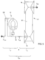
- FIG. 5 shows the basic structure of a conventional torque converter 10 and continuously variable transmission 12 existing drive train.
- An unillustrated motor in the form of a conventional internal combustion engine provides an engine speed n mot to the pump P of the torque converter 10.
- the turbine wheel T rotates at a speed n, a transmission input shaft 14 of the continuously variable transmission 12th
- the continuously variable transmission 12 consists, in a manner known per se, of two sets of conical disks 16 and 18, between which a traction means, for example a V-belt, or a Pressure medium, for example in the form of a link chain, rotates.
- a traction means for example a V-belt, or a Pressure medium, for example in the form of a link chain.
- a lock-up clutch ÜK is provided.
- the lock-up clutch is controlled taking certain criteria into account engaged or disengaged. From German published application DE 195 19 461 A1 it is known engage the lock-up clutch when the vehicle speed is a predetermined one Vehicle speed exceeds and then the lock-up clutch again disengage when the vehicle speed is below a second set vehicle speed falls, which is lower than the first-mentioned vehicle speed. From this publication, additional criteria for the Remove or engage the lock-up clutch to avoid torque surges at one sudden power request from the driver of the motor vehicle to the engine, i.e. the Internal combustion engine to mitigate.
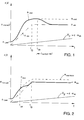
- Figure 1 shows a diagram of an accelerating motor vehicle in which the lock-up clutch according to the prior art when a certain is exceeded Vehicle speed is closed.
- a disadvantage of this conventional method is that the engine speed n mot oscillates beyond the desired desired value n mot setpoint.
- FIG. 2 shows an alternative method variant, which is also from the prior art is known.
- the procedure is the ratio of the continuously variable transmission continuously from i max towards longer transmission so that the transmission output speed and thus the vehicle speed increases steadily, although the transmission input speed n is a constant.
- a disadvantage of the method according to FIG. 2 is that after the lock-up clutch has started to engage the engine power drops because of the falling speed, so that none optimal acceleration is possible.
- the invention is therefore based on the object of a control or regulating method create it when operating a generic continuously variable transmission with hydrodynamic Converter and lock-up clutch allowed the engine speed during one Acceleration process more accurately in accordance with a desired engine speed bring to.
- the invention is also based on the object of preventing the engine from over-revving beyond a target engine speed with the shortest transmission ratio i max of the continuously variable transmission being accelerated.
- the solution according to the invention is given in that during the closing of the lock-up clutch, which are then eliminated due to Slippage changing translation of the hydraulic converter is compensated for by the Gear ratio of the continuously variable transmission accordingly in the direction of shorter gear ratios is adjusted.
- a control method is characterized in that when the shortest transmission ratio i max of the continuously variable transmission is set, the lock-up clutch is partially or completely closed when the motor vehicle is accelerating in order to avoid exceeding a target engine speed n should .
- the translation of the continuously adjustable transmission is adjusted so that the entire ratio of engine speed to gearbox output speed remains essentially the same. So while in conventional methods of Elimination of the slip occurring in the torque converter leads to the engine speed decreases, is provided according to the invention, the input speed of the continuously variable transmission by adjusting the ratio of the continuously variable transmission continuously so that the engine speed at a given vehicle speed, i.e. given output speed of the continuously variable transmission, remains constant.
- control method according to the invention is preferred to the control method to make that the translation of the continuously variable transmission as a manipulated variable is used to set the (measured) engine speed as a controlled variable to a predetermined value To regulate the target engine speed.
- the method according to the invention preferably further comprises determining the transmission output speed, in which the lock-up clutch is preferably to be engaged, to achieve on the one hand at a known closing time of the lock-up clutch that at At the end of the closing process the shortest transmission ratio is set to one to ensure maximum acceleration, and on the other hand that in the clutch in heat minimize implemented work.
- the gearbox output speed at which the lockup of the lock-up clutch must be started can advantageously be derived from the following relationship if the target engine speed and the clutch closing time are known, if the gradient with which the gearbox output speed changes, i.e. dn ab / dt, is known or can at least be estimated: n should ⁇ n from + dn from German * t close * i Max
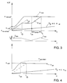
- FIG. 3 shows the method according to the invention, in the upper diagram of FIG. 3, as in FIGS. 1 and 2, rotational speed or vehicle speeds being recorded on the ordinate, while the abscissa represents the time axis.
- the transmission ratio i G is plotted over time in a representation provided with the same abscissa. High numerical values mean short gear ratios, the shortest gear ratio to be set is called i max .
- the engine reaches the target speed nriosoll .
- the transmission is adjusted in the direction of longer transmission ratios, so that despite continuously increasing vehicle speed V F and thus increasing transmission output speed n from the transmission input speed n on , and due to the constant slip, the engine speed n mot thus remains constant.
- the transmission output speed n ab reaches a value that can be determined if the gradient dn ab / dt is known or at least can be estimated.
- the angle in FIG. 3 can be used as an estimate. If one assumes that this slope remains constant, then one can deduce from the relationship n should ⁇ n concluding + dn from German + t close * i Max finally determine the speed of the transmission output shaft n at which it must be started to close the lock-up clutch, so that after the time t close at the time t 3 the shortest gear ratio i max is again available.
- the method can be designed as a control method if the engine speed n mot is measured and the transmission ratio i G is used as the manipulated variable.
- FIG. 4 shows that there may be cases in which the engine speed n mottheor threatens to exceed the setpoint a setpoint of the engine speed, although this has been counteracted by setting the longest gear ratio.
- the lock-up clutch at the time t ÜK be closed i min at the set longest transmission gear ratio, in order to lower mot n the engine speed by suppressing the slip of the hydrodynamic torque converter and thus to prevent the engine speed to n over the desired value increases.
- the lock-up clutch can be used to regulate the engine speed by using the clutch travel as a manipulated variable and opening the clutch again slightly when the speed drops, but closing it slightly when the engine speed is exceeded. Then, with further acceleration, the gear ratio is moved in the long direction at time t G
- the slip of the lock-up clutch is regulated if there is a regulation of the gear ratio to maintain the overall gear ratio is not possible to a sufficient extent.
Landscapes
- Engineering & Computer Science (AREA)
- General Engineering & Computer Science (AREA)
- Mechanical Engineering (AREA)
- Control Of Fluid Gearings (AREA)
Applications Claiming Priority (2)
| Application Number | Priority Date | Filing Date | Title |
|---|---|---|---|
| DE19640160 | 1996-09-28 | ||
| DE19640160A DE19640160A1 (de) | 1996-09-28 | 1996-09-28 | Steuerverfahren für ein stufenlos verstellbares Getriebe mit einem hydraulischen Drehmomentwandler und Überbrückungskupplung |
Publications (3)
| Publication Number | Publication Date |
|---|---|
| EP0833085A2 true EP0833085A2 (fr) | 1998-04-01 |
| EP0833085A3 EP0833085A3 (fr) | 1998-11-18 |
| EP0833085B1 EP0833085B1 (fr) | 2003-04-16 |
Family
ID=7807341
Family Applications (1)
| Application Number | Title | Priority Date | Filing Date |
|---|---|---|---|
| EP97115221A Expired - Lifetime EP0833085B1 (fr) | 1996-09-28 | 1997-09-03 | Système de commande pour un variateur continu de vitesse avec un convertisseur de couple hydraulique et un embrayage de pontage |
Country Status (2)
| Country | Link |
|---|---|
| EP (1) | EP0833085B1 (fr) |
| DE (2) | DE19640160A1 (fr) |
Cited By (2)
| Publication number | Priority date | Publication date | Assignee | Title |
|---|---|---|---|---|
| WO2000019132A1 (fr) * | 1998-09-28 | 2000-04-06 | Zf Batavia, L.L.C. | Commande du regime moteur par couplage de pontage du convertisseur dans le cas d'une transmission variable |
| WO2005010408A1 (fr) * | 2003-07-22 | 2005-02-03 | Daimlerchrysler Ag | Procede permettant de faire fonctionner une chaine cinematique dans un vehicule |
Families Citing this family (2)
| Publication number | Priority date | Publication date | Assignee | Title |
|---|---|---|---|---|
| DE10348763B4 (de) * | 2003-10-21 | 2006-09-28 | Zf Friedrichshafen Ag | Verfahren zum Verhindern einer fallenden Motordrehzahl beim Schließen der Wandlerkupplung in einem stufenlosen Getriebe |
| DE102007063091A1 (de) | 2007-12-28 | 2009-07-02 | Right-Way-Technologies Gmbh & Co. Kg | Hybridfermenter zur Erzeugung von methanreichem Biogas |
Citations (1)
| Publication number | Priority date | Publication date | Assignee | Title |
|---|---|---|---|---|
| DE19519461A1 (de) | 1994-05-25 | 1995-12-07 | Nissan Motor | Steuersystem für eine Kraftübertragung zwischen Motor und stufenlosem (CVT) Getriebe |
Family Cites Families (9)
| Publication number | Priority date | Publication date | Assignee | Title |
|---|---|---|---|---|
| JPH0694901B2 (ja) * | 1987-06-02 | 1994-11-24 | 富士重工業株式会社 | ロックアップトルコン付無段変速機の制御装置 |
| JPH03172667A (ja) * | 1989-11-30 | 1991-07-26 | Fuji Heavy Ind Ltd | 無段変速機の制御装置 |
| JP2987167B2 (ja) * | 1990-02-14 | 1999-12-06 | 富士重工業株式会社 | 無段変速機の制御装置 |
| JP2780431B2 (ja) * | 1990-04-06 | 1998-07-30 | トヨタ自動車株式会社 | 車両用無段変速機の変速比制御装置 |
| JP2663674B2 (ja) * | 1990-04-06 | 1997-10-15 | 日産自動車株式会社 | ロックアップクラッチの制御装置 |
| JP3318945B2 (ja) * | 1992-03-02 | 2002-08-26 | 株式会社日立製作所 | 自動車用制御装置、自動車制御システム及び自動車の制御方法 |
| DE4229585A1 (de) * | 1992-09-04 | 1994-03-10 | Zahnradfabrik Friedrichshafen | Vorrichtung zur Regelung des Übersetzungsverhältnisses eines stufenlosen Getriebes |
| US5417621A (en) * | 1993-12-22 | 1995-05-23 | Ford Motor Company | Driveaway lockup strategy for an infinitely variable tranmission with a hydrokinetic torque converter |
| JP3435896B2 (ja) * | 1995-05-29 | 2003-08-11 | 日産自動車株式会社 | 車両用無段変速機の変速制御装置 |
-
1996
- 1996-09-28 DE DE19640160A patent/DE19640160A1/de not_active Withdrawn
-
1997
- 1997-09-03 DE DE59709835T patent/DE59709835D1/de not_active Expired - Lifetime
- 1997-09-03 EP EP97115221A patent/EP0833085B1/fr not_active Expired - Lifetime
Patent Citations (1)
| Publication number | Priority date | Publication date | Assignee | Title |
|---|---|---|---|---|
| DE19519461A1 (de) | 1994-05-25 | 1995-12-07 | Nissan Motor | Steuersystem für eine Kraftübertragung zwischen Motor und stufenlosem (CVT) Getriebe |
Cited By (4)
| Publication number | Priority date | Publication date | Assignee | Title |
|---|---|---|---|---|
| WO2000019132A1 (fr) * | 1998-09-28 | 2000-04-06 | Zf Batavia, L.L.C. | Commande du regime moteur par couplage de pontage du convertisseur dans le cas d'une transmission variable |
| US6554737B1 (en) | 1998-09-28 | 2003-04-29 | Zf Batavia L.L.C. | Engine speed control via the torque converter lockup clutch of a continuously variable drive |
| WO2005010408A1 (fr) * | 2003-07-22 | 2005-02-03 | Daimlerchrysler Ag | Procede permettant de faire fonctionner une chaine cinematique dans un vehicule |
| US7189185B2 (en) | 2003-07-22 | 2007-03-13 | Daimlerchrysler Ag | Method for operating a drive train in a motor vehicle |
Also Published As
| Publication number | Publication date |
|---|---|
| DE59709835D1 (de) | 2003-05-22 |
| EP0833085A3 (fr) | 1998-11-18 |
| DE19640160A1 (de) | 1998-04-09 |
| EP0833085B1 (fr) | 2003-04-16 |
Similar Documents
| Publication | Publication Date | Title |
|---|---|---|
| DE4042092C2 (de) | Verfahren zum Steuern des Übersetzungsverhältnisses eines Riemengetriebes | |
| EP0517705B1 (fr) | Procede de changement de vitesse dans une transmission a variation discontinue de la vitesse | |
| EP0941164B1 (fr) | Dispositif et procede pour le reglage du rapport d'une transmission a changement de vitesses continu | |
| DE69905485T2 (de) | Verfahren zur steuerung des motordrehmoments während eines schaltvorganges | |
| DE69901441T2 (de) | Verfahren zum Betreiben eines stufenlosen Getriebes mit stätig gleitender Kupplung | |
| EP0970319B1 (fr) | Dispositif et procede pour reduire le patinage lors de la commande d'une transmission a changement de vitesses continu dans un vehicule a moteur | |
| EP0589916A1 (fr) | Procede pour la commande d'une transmission a variation continue d'un vehicule automobile. | |
| DE3628490A1 (de) | System zum steuern eines leistungsabgabesystems mit einem stufenlosen getriebe | |
| EP1117954B1 (fr) | Commande du regime moteur par couplage de pontage du convertisseur dans le cas d'une transmission variable | |
| DE102005014504B4 (de) | Verfahren zum Regeln des Kupplungsschlupfs während Schaltvorgängen eines Automatikgetriebes | |
| DE19702834B4 (de) | Steuereinheit und Verfahren zum Steuern einer Sperrkupplung während eines Schubbetriebs eines Fahrzeuges | |
| DE69620123T2 (de) | Verfahren zur Steuerung beim Schalten vom dritten in den ersten Gang | |
| DE69025366T2 (de) | Regelungsverfahren und Vorrichtung zur Regelung eines stufenlosen Getriebes | |
| DE19603239B4 (de) | Verfahren zur Erhöhung der Drehzahl oder des Drehmoments eines Fahrzeugmotors | |
| DE102010001282A1 (de) | Verfahren zur Steuerung eines Antriebssystems eines Fahrzeugs | |
| DE60011066T2 (de) | Stufenlos verstellbares Getriebe und Steuerungsverfahren dafür | |
| DE3619900C2 (de) | Steuerung einer Überbrückungskupplung zwischen einem Eingangs- und Ausgangselement eines hydraulischen Fahrzeug-Automatikgetriebes | |
| EP0833085B1 (fr) | Système de commande pour un variateur continu de vitesse avec un convertisseur de couple hydraulique et un embrayage de pontage | |
| DE19614545A1 (de) | Stufenloses Getriebe-System für ein Kraftfahrzeug | |
| EP0860633B1 (fr) | Méthode de commande d'un embrayage de pontage de convertisseur de couple pendant le démarrage de véhicule | |
| DE10247970A1 (de) | Verfahren zum Anfahren eines Kraftfahrzeuges | |
| DE3425757A1 (de) | Synchronisiertes mechanisch-hydrostatisches getriebe | |
| DE69502248T2 (de) | Stufenloses Getriebe | |
| EP0728966B1 (fr) | Soupape de passage / commande pour convertisseurs de couple hydrodynamiques de transmissions automatiques | |
| EP2310717B1 (fr) | Procédé de fonctionnement d un système de transmission de couple et système de transmission de couple |
Legal Events
| Date | Code | Title | Description |
|---|---|---|---|
| PUAI | Public reference made under article 153(3) epc to a published international application that has entered the european phase |
Free format text: ORIGINAL CODE: 0009012 |
|
| AK | Designated contracting states |
Kind code of ref document: A2 Designated state(s): DE FR GB IT |
|
| PUAL | Search report despatched |
Free format text: ORIGINAL CODE: 0009013 |
|
| AK | Designated contracting states |
Kind code of ref document: A3 Designated state(s): AT BE CH DE DK ES FI FR GB GR IE IT LI LU MC NL PT SE |
|
| 17P | Request for examination filed |
Effective date: 19990518 |
|
| AKX | Designation fees paid |
Free format text: DE FR GB IT |
|
| 17Q | First examination report despatched |
Effective date: 20010206 |
|
| GRAG | Despatch of communication of intention to grant |
Free format text: ORIGINAL CODE: EPIDOS AGRA |
|
| GRAG | Despatch of communication of intention to grant |
Free format text: ORIGINAL CODE: EPIDOS AGRA |
|
| GRAH | Despatch of communication of intention to grant a patent |
Free format text: ORIGINAL CODE: EPIDOS IGRA |
|
| GRAH | Despatch of communication of intention to grant a patent |
Free format text: ORIGINAL CODE: EPIDOS IGRA |
|
| GRAA | (expected) grant |
Free format text: ORIGINAL CODE: 0009210 |
|
| AK | Designated contracting states |
Designated state(s): DE FR GB IT |
|
| PG25 | Lapsed in a contracting state [announced via postgrant information from national office to epo] |
Ref country code: GB Free format text: LAPSE BECAUSE OF FAILURE TO SUBMIT A TRANSLATION OF THE DESCRIPTION OR TO PAY THE FEE WITHIN THE PRESCRIBED TIME-LIMIT Effective date: 20030416 |
|
| REG | Reference to a national code |
Ref country code: GB Ref legal event code: FG4D Free format text: NOT ENGLISH |
|
| REF | Corresponds to: |
Ref document number: 59709835 Country of ref document: DE Date of ref document: 20030522 Kind code of ref document: P |
|
| GBV | Gb: ep patent (uk) treated as always having been void in accordance with gb section 77(7)/1977 [no translation filed] |
Effective date: 20030416 |
|
| ET | Fr: translation filed | ||
| ET1 | Fr: translation filed ** revision of the translation of the patent or the claims | ||
| PLBE | No opposition filed within time limit |
Free format text: ORIGINAL CODE: 0009261 |
|
| STAA | Information on the status of an ep patent application or granted ep patent |
Free format text: STATUS: NO OPPOSITION FILED WITHIN TIME LIMIT |
|
| 26N | No opposition filed |
Effective date: 20040119 |
|
| PGFP | Annual fee paid to national office [announced via postgrant information from national office to epo] |
Ref country code: DE Payment date: 20090930 Year of fee payment: 13 |
|
| PGFP | Annual fee paid to national office [announced via postgrant information from national office to epo] |
Ref country code: FR Payment date: 20101013 Year of fee payment: 14 |
|
| PGFP | Annual fee paid to national office [announced via postgrant information from national office to epo] |
Ref country code: IT Payment date: 20100930 Year of fee payment: 14 |
|
| REG | Reference to a national code |
Ref country code: DE Ref legal event code: R119 Ref document number: 59709835 Country of ref document: DE Effective date: 20110401 |
|
| PG25 | Lapsed in a contracting state [announced via postgrant information from national office to epo] |
Ref country code: DE Free format text: LAPSE BECAUSE OF NON-PAYMENT OF DUE FEES Effective date: 20110401 |
|
| PG25 | Lapsed in a contracting state [announced via postgrant information from national office to epo] |
Ref country code: IT Free format text: LAPSE BECAUSE OF NON-PAYMENT OF DUE FEES Effective date: 20110903 |
|
| REG | Reference to a national code |
Ref country code: FR Ref legal event code: ST Effective date: 20120531 |
|
| PG25 | Lapsed in a contracting state [announced via postgrant information from national office to epo] |
Ref country code: FR Free format text: LAPSE BECAUSE OF NON-PAYMENT OF DUE FEES Effective date: 20110930 |