EP0833117A2 - Récipient sous pression et procédé pour sa fabrication - Google Patents
Récipient sous pression et procédé pour sa fabrication Download PDFInfo
- Publication number
- EP0833117A2 EP0833117A2 EP97402222A EP97402222A EP0833117A2 EP 0833117 A2 EP0833117 A2 EP 0833117A2 EP 97402222 A EP97402222 A EP 97402222A EP 97402222 A EP97402222 A EP 97402222A EP 0833117 A2 EP0833117 A2 EP 0833117A2
- Authority
- EP
- European Patent Office
- Prior art keywords
- cylindrical body
- closure
- annular
- open end
- annular flange
- Prior art date
- Legal status (The legal status is an assumption and is not a legal conclusion. Google has not performed a legal analysis and makes no representation as to the accuracy of the status listed.)
- Withdrawn
Links
Images


Classifications
-
- F—MECHANICAL ENGINEERING; LIGHTING; HEATING; WEAPONS; BLASTING
- F25—REFRIGERATION OR COOLING; COMBINED HEATING AND REFRIGERATION SYSTEMS; HEAT PUMP SYSTEMS; MANUFACTURE OR STORAGE OF ICE; LIQUEFACTION SOLIDIFICATION OF GASES
- F25B—REFRIGERATION MACHINES, PLANTS OR SYSTEMS; COMBINED HEATING AND REFRIGERATION SYSTEMS; HEAT PUMP SYSTEMS
- F25B43/00—Arrangements for separating or purifying gases or liquids; Arrangements for vaporising the residuum of liquid refrigerant, e.g. by heat
- F25B43/006—Accumulators
-
- B—PERFORMING OPERATIONS; TRANSPORTING
- B23—MACHINE TOOLS; METAL-WORKING NOT OTHERWISE PROVIDED FOR
- B23K—SOLDERING OR UNSOLDERING; WELDING; CLADDING OR PLATING BY SOLDERING OR WELDING; CUTTING BY APPLYING HEAT LOCALLY, e.g. FLAME CUTTING; WORKING BY LASER BEAM
- B23K20/00—Non-electric welding by applying impact or other pressure, with or without the application of heat, e.g. cladding or plating
- B23K20/12—Non-electric welding by applying impact or other pressure, with or without the application of heat, e.g. cladding or plating the heat being generated by friction; Friction welding
-
- B—PERFORMING OPERATIONS; TRANSPORTING
- B23—MACHINE TOOLS; METAL-WORKING NOT OTHERWISE PROVIDED FOR
- B23K—SOLDERING OR UNSOLDERING; WELDING; CLADDING OR PLATING BY SOLDERING OR WELDING; CUTTING BY APPLYING HEAT LOCALLY, e.g. FLAME CUTTING; WORKING BY LASER BEAM
- B23K20/00—Non-electric welding by applying impact or other pressure, with or without the application of heat, e.g. cladding or plating
- B23K20/12—Non-electric welding by applying impact or other pressure, with or without the application of heat, e.g. cladding or plating the heat being generated by friction; Friction welding
- B23K20/122—Non-electric welding by applying impact or other pressure, with or without the application of heat, e.g. cladding or plating the heat being generated by friction; Friction welding using a non-consumable tool, e.g. friction stir welding
-
- B—PERFORMING OPERATIONS; TRANSPORTING
- B23—MACHINE TOOLS; METAL-WORKING NOT OTHERWISE PROVIDED FOR
- B23K—SOLDERING OR UNSOLDERING; WELDING; CLADDING OR PLATING BY SOLDERING OR WELDING; CUTTING BY APPLYING HEAT LOCALLY, e.g. FLAME CUTTING; WORKING BY LASER BEAM
- B23K20/00—Non-electric welding by applying impact or other pressure, with or without the application of heat, e.g. cladding or plating
- B23K20/12—Non-electric welding by applying impact or other pressure, with or without the application of heat, e.g. cladding or plating the heat being generated by friction; Friction welding
- B23K20/129—Non-electric welding by applying impact or other pressure, with or without the application of heat, e.g. cladding or plating the heat being generated by friction; Friction welding specially adapted for particular articles or work
-
- B—PERFORMING OPERATIONS; TRANSPORTING
- B60—VEHICLES IN GENERAL
- B60H—ARRANGEMENTS OF HEATING, COOLING, VENTILATING OR OTHER AIR-TREATING DEVICES SPECIALLY ADAPTED FOR PASSENGER OR GOODS SPACES OF VEHICLES
- B60H1/00—Heating, cooling or ventilating devices
- B60H1/32—Cooling devices
- B60H1/3204—Cooling devices using compression
- B60H1/3229—Cooling devices using compression characterised by constructional features, e.g. housings, mountings, conversion systems
-
- B—PERFORMING OPERATIONS; TRANSPORTING
- B23—MACHINE TOOLS; METAL-WORKING NOT OTHERWISE PROVIDED FOR
- B23K—SOLDERING OR UNSOLDERING; WELDING; CLADDING OR PLATING BY SOLDERING OR WELDING; CUTTING BY APPLYING HEAT LOCALLY, e.g. FLAME CUTTING; WORKING BY LASER BEAM
- B23K2101/00—Articles made by soldering, welding or cutting
- B23K2101/04—Tubular or hollow articles
- B23K2101/06—Tubes
-
- B—PERFORMING OPERATIONS; TRANSPORTING
- B23—MACHINE TOOLS; METAL-WORKING NOT OTHERWISE PROVIDED FOR
- B23K—SOLDERING OR UNSOLDERING; WELDING; CLADDING OR PLATING BY SOLDERING OR WELDING; CUTTING BY APPLYING HEAT LOCALLY, e.g. FLAME CUTTING; WORKING BY LASER BEAM
- B23K2101/00—Articles made by soldering, welding or cutting
- B23K2101/04—Tubular or hollow articles
- B23K2101/12—Vessels
-
- F—MECHANICAL ENGINEERING; LIGHTING; HEATING; WEAPONS; BLASTING
- F25—REFRIGERATION OR COOLING; COMBINED HEATING AND REFRIGERATION SYSTEMS; HEAT PUMP SYSTEMS; MANUFACTURE OR STORAGE OF ICE; LIQUEFACTION SOLIDIFICATION OF GASES
- F25B—REFRIGERATION MACHINES, PLANTS OR SYSTEMS; COMBINED HEATING AND REFRIGERATION SYSTEMS; HEAT PUMP SYSTEMS
- F25B2400/00—Component parts or details not otherwise provided for in this subclass
- F25B2400/16—Receivers
- F25B2400/162—Receivers characterised by the plug or stop
-
- Y—GENERAL TAGGING OF NEW TECHNOLOGICAL DEVELOPMENTS; GENERAL TAGGING OF CROSS-SECTIONAL TECHNOLOGIES SPANNING OVER SEVERAL SECTIONS OF THE IPC; TECHNICAL SUBJECTS COVERED BY FORMER USPC CROSS-REFERENCE ART COLLECTIONS [XRACs] AND DIGESTS
- Y10—TECHNICAL SUBJECTS COVERED BY FORMER USPC
- Y10T—TECHNICAL SUBJECTS COVERED BY FORMER US CLASSIFICATION
- Y10T29/00—Metal working
- Y10T29/49—Method of mechanical manufacture
- Y10T29/4935—Heat exchanger or boiler making
- Y10T29/49359—Cooling apparatus making, e.g., air conditioner, refrigerator
-
- Y—GENERAL TAGGING OF NEW TECHNOLOGICAL DEVELOPMENTS; GENERAL TAGGING OF CROSS-SECTIONAL TECHNOLOGIES SPANNING OVER SEVERAL SECTIONS OF THE IPC; TECHNICAL SUBJECTS COVERED BY FORMER USPC CROSS-REFERENCE ART COLLECTIONS [XRACs] AND DIGESTS
- Y10—TECHNICAL SUBJECTS COVERED BY FORMER USPC
- Y10T—TECHNICAL SUBJECTS COVERED BY FORMER US CLASSIFICATION
- Y10T29/00—Metal working
- Y10T29/49—Method of mechanical manufacture
- Y10T29/49808—Shaping container end to encapsulate material
-
- Y—GENERAL TAGGING OF NEW TECHNOLOGICAL DEVELOPMENTS; GENERAL TAGGING OF CROSS-SECTIONAL TECHNOLOGIES SPANNING OVER SEVERAL SECTIONS OF THE IPC; TECHNICAL SUBJECTS COVERED BY FORMER USPC CROSS-REFERENCE ART COLLECTIONS [XRACs] AND DIGESTS
- Y10—TECHNICAL SUBJECTS COVERED BY FORMER USPC
- Y10T—TECHNICAL SUBJECTS COVERED BY FORMER US CLASSIFICATION
- Y10T29/00—Metal working
- Y10T29/49—Method of mechanical manufacture
- Y10T29/49826—Assembling or joining
- Y10T29/49908—Joining by deforming
- Y10T29/49925—Inward deformation of aperture or hollow body wall
- Y10T29/49927—Hollow body is axially joined cup or tube
Definitions
- This invention relates to a pressure vessel and to a method of manufacturing the pressure vessel. More particularly, this invention relates to a pressure vessel of the type used in an automotive air conditioning system such as a refrigerant receiver or an accumulator dehydrator.
- U.S. Patent 5,191,775 discloses a receiver of the type used in an automotive air conditioning system and a method for the manufacture of such receiver.
- the receiver of the Shiina et al. reference is composed of a generally cylindrical body having a thin annular wall, a first integral and unitary end, and a disk-shaped closure member, commonly referred to as a puck, inserted into an opposed open end of the cylindrical body.
- the closure member is secured to the cylindrical body, after insertion of a desiccant material or other elements of the receiver, as used in a refrigerant circuit, into the interior of the cylindrical body.
- the open end of the cylindrical body is reshaped by electromagnetic forming, after insertion of the closure member, to closely conform the interior of the open end of the cylindrical body to the exterior of the closure member to thereby secure the closure member and the cylindrical body to one another.
- Shiina et al. teach that the closure member and cylindrical body are sealed using O-rings. Nevertheless, the assembly of the closure member and the cylindrical body to one another according to this reference does not result in a receiver that is pressure-tight, i.e.,. that it eliminates all leak paths for the molecules of refrigerant fluid. Consequently, the O-rings must be used between the exterior of the closure and the interior of the cylindrical body to retain the refrigerant fluid within the receiver of this reference.
- U.S. Patent 5,425,250 to Hutchinson et al., also discloses a receiver for an automotive air conditioning system that consists of a generally cylindrical aluminum body with a thin annular wall and an initially open end which is closed, after the insertion of a desiccant material or other elements into the cylindrical body, by a disk-shaped aluminum closure member, or puck, inserted into the open end of the cylindrical body.
- the closure member is joined to the cylindrical body using an annular weld.
- welded joints, or even brazed joints, in an air conditioning system receiver are subject to leakage, and, therefore, have not been totally satisfactory in service because of such phenomena.
- the receiver of the present invention and by the method of its manufacture, in which an aluminum disk-shaped closure member, or puck, is secured to an initially open end of a generally cylindrical thin-walled aluminum body utilizing a spin welding process.
- the spin welding process of the present invention is preferably used in conjunction with a rolling operation to roll an annular portion of the wall of the cylindrical body into an annular recess in the exterior of the closure member to form a positive mechanical lock between the cylindrical body and the closure member.
- the positive mechanical lock between the closure member and the cylindrical body which results from the rolling operation, serves to overcome the tendency of the closure member to eject from the receiver under significant internal pressure, and the spin welding step of the present invention results in a continuous, leak-free seam between the cylindrical body and the closure member, eliminating the need for an O-ring or other sealing member therebetween, and does so without using a conventional welding or brazing operation to form a seam between the closure member and the cylindrical body, thereby eliminating the known processing problems associated with any such conventional welding operation.
- the closure member and the cylindrical body are provided with relatively thin annular flanges, which are spaced close to one another when the closure member and the cylindrical body are properly positioned for the beginning of the spin welding operation.
- the annular flanges of the closure member and the cylindrical body extend in a direction essentially parallel to a longitudinal central axis of the cylindrical body, in which case the spin welding step is preferably accomplished by spinning a spinning tool, whose axis of rotation is aligned with the longitudinal central axis of the cylindrical body, relative to the cylindrical body and the closure member while they are held in fixed positions.
- the annular flanges of the closure member and the cylindrical body extend substantially perpendicular to the longitudinal central axis of the cylindrical body, in which case the welding is preferably accomplished by rotating the closure member and the cylindrical body with respect to a tool moving rectilinearly along an axis that extends substantially perpendicular to the longitudinal central axis of the cylindrical body.
- an object of the present invention to provide an improved pressure vessel of a type having a cylindrical body having a thin annular wall and a closure member inserted into an initially open end of the cylindrical body and secured thereto, as well as an improved method for manufacturing such a pressure vessel.
- FIG. 1 illustrates a cylindrical body 10, shown fragmentarily, the cylindrical body 10 having an initially open end 12 and preferably being formed from aluminum or an aluminum alloy.
- the cylindrical body 10 has a thin annular wall 14, and the end 12 of the cylindrical body 10 is preferably enlarged, for example, by an impacting or expanding operation or as part of a deep draw process, such that the cylindrical body 10 preferably will have an outwardly projecting shoulder 16 which may, as illustrated in FIG. 1, also extend upwardly toward the open end 12.
- the open end 12 of the cylindrical body 10 is to be closed by a closure or puck 20 that is inserted into the open end 12, and is later secured to the cylindrical body 10 as will be hereinafter described more fully.
- the closure 20 is formed of a material that is compatible with the material of the cylindrical body 10, so as to be weldable to the cylindrical body 10 by spin welding.
- the closure 20 is also preferably formed of aluminum or an aluminum alloy when the cylindrical body 10 is formed of such a material.
- the closure 20 is preferably formed in its illustrated complex configuration by machining in a known manner, and has a main body portion 22 that fits snugly within the open end 12 of the cylindrical body 10, a smaller end portion 24 and a shoulder 26 extending between the main body portion 22 and the end portion 24.
- the shoulder 26 of the closure 20 extends substantially or approximately parallel to the shoulder 16 of the cylindrical body 10.
- the closure 20 includes a relatively thin, annular flange 28 extending outwardly from the main body portion 22 of the closure 20 and substantially parallel to a longitudinal central axis of the cylindrical body 10.
- the annular flange 28 is spaced close to an outermost portion 18 of the initially open end 12 of the cylindrical body 10, for reasons which will be hereinafter described more fully.
- the axial position of the closure 20 relative to the open end 12 of the cylindrical body 10, and thus the axial position of the annular flange 28 relative to the outermost portion 18 of the open end 12, is preferably accurately fixed by the shoulder 16 of the cylindrical body 10, which limits the distance the closure 20 can be inserted into the cylindrical body 10.
- the main body portion 22 of the closure 20 is also provided with an annular groove 30.
- a rolling tool R preferably engages the exterior of the open end 12 of the cylindrical body 10, at a location in alignment with the annular groove 30, to roll a portion 12a of the open end 12 into the annular groove 30 as illustrated in FIG. 2.
- the engagement between the rolled portion 12a of the open end 12 of the cylindrical body and the annular groove 30 of the closure 20 serves to lock the closure 20 and the cylindrical body 10 to one another and prevent ejection of the closure 20 from the cylindrical body 10 as a result of positive pressure within the cylindrical body 10, which is common within a receiver for an automotive air conditioning system, the intended application for the combined cylindrical body 10 and closure 20 at the conclusion of the manufacturing operations to be performed thereon.
- the cylindrical body 10 and closure 20 now mechanically locked together but not sealed, are axially aligned with a spinning tool S, which is caused to spin at a relatively high rotational velocity about its central axis and is axially translated toward the cylindrical body 10 and closure 20, while the cylindrical body 10 is held in a fixed position, for example, in a conventional chuck, not shown.
- the axial advance of the spinning tool S gradually traps the outermost portion 18 of the open end 12 of the cylindrical body 10 and the annular flange 28 of the closure 20 in a generally V-shaped groove G of the spinning tool S to urge the outermost portion 18 and the annular flange 28 toward one another.
- the high rotational speed spinning of the spinning tool S relative to the fixed cylindrical body 10 generates heat sufficient to weld the outermost portion 18 and the annular flange 28 to one another in a continuous piece, which will be completely leak-free as opposed to a seam formed by brazing, a conventional process for joining aluminum components to one another, or by any other welding process.
- the nonillustrated end of the cylindrical body 10 that is opposed to the open end 12 is preferably integral to the annular wall 14, or further the cylindrical body 10 may be formed in a unitary one-piece configuration by a deep drawing operation as is known in the art.
- the aforesaid U.S. Patent 5,191,775 discloses such a one-piece body, which is identified by reference numeral 11 therein.
- the nonillustrated end of the cylindrical body 10 may also be closed by a separate closure, not shown, similar to the closure 20 that is affixed to the open end 12 of the cylindrical body 10, and affixed thereto in a similar manner, as heretofore described.
- closure 20 may be, and preferably is, provided with openings extending therethrough to permit necessary inlet and outlet tubes, not shown, to be affixed to the closure 20 for the purpose of permitting refrigerant fluid to flow into and out of the cylindrical body 10, as is also shown, for example, in the aforesaid U.S. Patent 5,191,775.
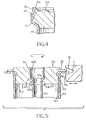
- FIG. 5 illustrates a vessel that is made up of a cylindrical body 40 with an initially open end 42.
- the cylindrical body 40 is preferably formed of aluminum or an aluminum alloy and is defined by an annular wall 44.
- the free end or the initially open end 42 of the cylindrical body 40 is provided with a radially outwardly projecting annular flange 48.
- a closure 50 which is also preferably formed of aluminum or an aluminum alloy and preferably by machining, has a radially outwardly projecting annular flange 58, and is inserted into the open end 42 of the cylindrical body 40 until the radial flange 58 of the closure 50 abuts against the radial flange 48 of the cylindrical body 40 and the radial flanges 48 and 58 are aligned for further processing.
- the closure 50 also has an annular groove 60 in its exterior side, similar to the annular groove 30 of the closure 20 of the embodiment of FIGS. 1 through 4, and the annular wall 44 of the cylindrical body 40 preferably is rolled into the annular groove 60 to positively lock the closure 50 and the cylindrical body 40 to one another, though such step is not positively illustrated in FIG. 5.
- the closure 50 has an opening 62 extending therethrough, the opening 62 having a small diameter innermost portion 62a and a larger diameter outermost portion 62b, separated by an annular shoulder 62c.
- An annular tube 70 is inserted into the cylindrical body 40 through the opening 62 to introduce refrigerant fluid into the cylindrical body 40.
- the tube 70 has an outermost annular flange 70a that abuts against the annular shoulder 62c of the opening 62, and a bead 70b that abuts against an inner surface 64 of the closure 50 to positively position the tube 70 axially with respect to the closure 50.
- the bead 70b may be formed using any known process such as cold forming or, preferably, rolling.
- the assembly of the cylindrical body 40 and the closure 50 is caused to spin about the longitudinal central axis of the cylindrical body 40 at a relatively high rotational velocity, and a translating tool T is advanced toward the annular flange 48 and the annular flange 58 while the cylindrical body 40 and the closure 50 are rotating.
- the tool T has a generally V-shaped groove G1 that engages the annular flange 48 and the annular flange 58 while they are spinning, to generate a level of heat that will cause the annular flange 48 and the annular flange 58 to fuse, or weld, to one another to eliminate any potential leak path for the molecules of the refrigerant fluid.
- a pressure vessel formed by the method of FIG. 5 will, thus, have an external lip that can be used to facilitate the assembly of such a pressure vessel to an automotive vehicle as well as provide a sealed, secured pressure vessel.
Landscapes
- Engineering & Computer Science (AREA)
- Mechanical Engineering (AREA)
- Physics & Mathematics (AREA)
- Thermal Sciences (AREA)
- Power Engineering (AREA)
- Chemical & Material Sciences (AREA)
- Analytical Chemistry (AREA)
- General Engineering & Computer Science (AREA)
- Pressure Vessels And Lids Thereof (AREA)
- Pressure Welding/Diffusion-Bonding (AREA)
- Filling Or Discharging Of Gas Storage Vessels (AREA)
- Shaping Metal By Deep-Drawing, Or The Like (AREA)
- Lining Or Joining Of Plastics Or The Like (AREA)
- Air-Conditioning For Vehicles (AREA)
Applications Claiming Priority (2)
| Application Number | Priority Date | Filing Date | Title |
|---|---|---|---|
| US721829 | 1996-09-27 | ||
| US08/721,829 US5855293A (en) | 1996-09-27 | 1996-09-27 | Pressure vessel and method of manufacture thereof |
Publications (2)
| Publication Number | Publication Date |
|---|---|
| EP0833117A2 true EP0833117A2 (fr) | 1998-04-01 |
| EP0833117A3 EP0833117A3 (fr) | 2000-01-05 |
Family
ID=24899482
Family Applications (1)
| Application Number | Title | Priority Date | Filing Date |
|---|---|---|---|
| EP97402222A Withdrawn EP0833117A3 (fr) | 1996-09-27 | 1997-09-24 | Récipient sous pression et procédé pour sa fabrication |
Country Status (10)
| Country | Link |
|---|---|
| US (2) | US5855293A (fr) |
| EP (1) | EP0833117A3 (fr) |
| JP (1) | JP3220938B2 (fr) |
| CN (1) | CN1182195A (fr) |
| AR (1) | AR009953A1 (fr) |
| AU (1) | AU731380B2 (fr) |
| BR (1) | BR9704892A (fr) |
| CA (1) | CA2216290C (fr) |
| CZ (1) | CZ292897A3 (fr) |
| ZA (1) | ZA978532B (fr) |
Cited By (5)
| Publication number | Priority date | Publication date | Assignee | Title |
|---|---|---|---|---|
| WO1999054081A1 (fr) * | 1998-04-22 | 1999-10-28 | The Welding Institute | Enceintes resistant a la corrosion et leurs procedes de fabrication |
| EP1274074A2 (fr) * | 2001-07-05 | 2003-01-08 | Samsung Electronics Co., Ltd. | Disque à stockage haute densité |
| EP1353134A1 (fr) * | 2002-04-11 | 2003-10-15 | SKG Italiana S.P.A. | Accumulateur sécheur |
| WO2004025196A1 (fr) * | 2002-08-31 | 2004-03-25 | Behr Gmbh & Co. | Condenseur d'agent refrigerant, notamment pour installations de conditionnement d'air d'automobile |
| EP1591814A1 (fr) | 2004-04-28 | 2005-11-02 | Furukawa Electric North America Inc. | Câble à fibres optiques à haute densité |
Families Citing this family (13)
| Publication number | Priority date | Publication date | Assignee | Title |
|---|---|---|---|---|
| US6568204B2 (en) | 2001-10-30 | 2003-05-27 | Automotive Fluid Systems, Inc. | Baffle connection for an accumulator and related method of manufacturing |
| JP2004132516A (ja) * | 2002-10-15 | 2004-04-30 | Unisia Jkc Steering System Co Ltd | 軸部材と円筒部材の結合構造及び結合方法 |
| JP2004322133A (ja) | 2003-04-23 | 2004-11-18 | Kubota Tekkosho:Kk | 磁性体と非磁性体の接合方法 |
| CN1322284C (zh) * | 2004-09-23 | 2007-06-20 | 王斌 | 长方体承压水箱及其制作方法 |
| FR2879166B1 (fr) * | 2004-12-09 | 2007-02-16 | Valeo Thermique Moteur Sas | Reservoir de fluide a paroi tubulaire, en particulier pour condenseur de climatisation. |
| ITMI20051588A1 (it) * | 2005-08-23 | 2007-02-24 | Ti Automotive Cisliano S R L | Elemento a tenuta per dispositivo di refrigerazione |
| US7726542B2 (en) * | 2008-06-25 | 2010-06-01 | Gm Global Technology Operations, Inc. | Friction-welded assembly with interlocking feature and method for forming the assembly |
| FR2954198B1 (fr) * | 2009-12-22 | 2012-02-03 | Valeo Systemes Thermiques | Procede de brasage d'un composant de circuit de climatisation comportant une bouteille reservoir de fluide refrigerant et une telle bouteille. |
| US8540103B2 (en) * | 2010-02-08 | 2013-09-24 | Jack D Lollis | Closure for pressure vessels |
| DE102014220401A1 (de) * | 2014-10-08 | 2016-04-14 | Mahle International Gmbh | Kältemittelbehälter für eine Kälteanlage |
| DE102015205553A1 (de) * | 2015-03-26 | 2016-09-29 | Mahle International Gmbh | Behälter einer Klimaanlage |
| DE102015216371B4 (de) * | 2015-08-27 | 2021-10-07 | Schaeffler Technologies AG & Co. KG | Kunststoffgehäuse mit einer Ultraschallschweißverbindung, insbesondere für einen Hydrostataktor und Hydrostataktor mit diesem |
| CN106965453A (zh) * | 2017-04-11 | 2017-07-21 | 东莞市金瑞五金股份有限公司 | 一种储液器的制造方法 |
Citations (5)
| Publication number | Priority date | Publication date | Assignee | Title |
|---|---|---|---|---|
| US4628704A (en) | 1983-09-06 | 1986-12-16 | Michigan Special Products, Inc. | Surge tank for air-conditioning compressor |
| US4675971A (en) | 1985-12-03 | 1987-06-30 | Michigan Special Products, Inc. | Desiccant assembly for refrigeration circuit and method |
| US5191775A (en) | 1988-10-31 | 1993-03-09 | Showa Aluminum Corporation | Refrigerant receiver |
| US5245842A (en) | 1992-05-01 | 1993-09-21 | Fayette Tubular Technology Corporation | Receiver dryer |
| US5425250A (en) | 1994-02-25 | 1995-06-20 | Eaton Corporation | Receiver/dryer |
Family Cites Families (21)
| Publication number | Priority date | Publication date | Assignee | Title |
|---|---|---|---|---|
| US1696996A (en) * | 1927-03-29 | 1929-01-01 | Beath Lancelot Brisbin | Steel barrel |
| US2257697A (en) * | 1939-04-17 | 1941-09-30 | Archie W Mcclary | Container |
| US2388300A (en) * | 1943-05-07 | 1945-11-06 | Louis B Wackman | Method of making reinforced chime construction for cans or containers |
| US3452897A (en) * | 1965-01-05 | 1969-07-01 | Myron L Anthony | Methods of sealing cylindrical thinwall ductile metal can bodies |
| US3779446A (en) * | 1971-10-13 | 1973-12-18 | J Lemelson | Welding apparatus |
| DE2930991C2 (de) * | 1979-07-31 | 1984-04-05 | Nukem Gmbh, 6450 Hanau | Behälter zur Aufnahme und Lagerung abgebrannter Brennelemente |
| US4341092A (en) * | 1980-11-20 | 1982-07-27 | Liquid Modulators, Inc. | Liquid modulator |
| US4506519A (en) * | 1983-08-24 | 1985-03-26 | Tecumseh Products Company | Hermetic compressor discharge line thermal block |
| DE3765076D1 (de) * | 1986-10-13 | 1990-10-25 | Lin Pac Mouldings | Kunststoffbehaltereinheit. |
| US4788833A (en) * | 1988-02-18 | 1988-12-06 | Frigette Corporation | Drier for air conditioning system |
| US4838040A (en) * | 1988-03-30 | 1989-06-13 | Freeman Clarence S | Air conditioner dryer utilizing water-encapsulating polymers |
| US4992166A (en) * | 1988-06-13 | 1991-02-12 | Facet Enterprises, Inc. | Plastic fluid filter and method for manufacturing same |
| JPH0271067A (ja) * | 1988-09-05 | 1990-03-09 | Showa Alum Corp | 受液器 |
| JPH0648283Y2 (ja) * | 1989-03-13 | 1994-12-12 | カルソニック株式会社 | リキッドタンク |
| US5179780A (en) * | 1991-11-12 | 1993-01-19 | General Motors Corporation | Universal seamless receiver-dehydrator assembly for an automotive air conditioning system |
| GB9125978D0 (en) * | 1991-12-06 | 1992-02-05 | Welding Inst | Hot shear butt welding |
| US5201792A (en) * | 1991-12-23 | 1993-04-13 | Ford Motor Company | Accumulator for vehicle air conditioning system |
| US5201195A (en) * | 1992-04-27 | 1993-04-13 | General Motors Corporation | Bi-flow receiver/dehydrator for refrigeration system |
| US5395509A (en) * | 1992-07-06 | 1995-03-07 | Valycontrol S.A. De C.V. | Container for a refrigerant system filter |
| US5365751A (en) * | 1993-09-13 | 1994-11-22 | General Motors Corporation | Universal accumulator dehydrator assembly |
| US5774982A (en) * | 1994-03-16 | 1998-07-07 | Eaton Corporation | Conduit attachment to receiver/drier or accumulator |
-
1996
- 1996-09-27 US US08/721,829 patent/US5855293A/en not_active Expired - Fee Related
-
1997
- 1997-09-17 CZ CZ972928A patent/CZ292897A3/cs unknown
- 1997-09-18 AU AU38326/97A patent/AU731380B2/en not_active Ceased
- 1997-09-23 ZA ZA9708532A patent/ZA978532B/xx unknown
- 1997-09-23 CA CA002216290A patent/CA2216290C/fr not_active Expired - Fee Related
- 1997-09-24 EP EP97402222A patent/EP0833117A3/fr not_active Withdrawn
- 1997-09-26 AR ARP970104452A patent/AR009953A1/es unknown
- 1997-09-26 BR BR9704892A patent/BR9704892A/pt not_active IP Right Cessation
- 1997-09-27 CN CN97121385A patent/CN1182195A/zh active Pending
- 1997-09-29 JP JP26345897A patent/JP3220938B2/ja not_active Expired - Fee Related
-
1998
- 1998-11-12 US US09/190,544 patent/US6199261B1/en not_active Expired - Lifetime
Patent Citations (6)
| Publication number | Priority date | Publication date | Assignee | Title |
|---|---|---|---|---|
| US4628704A (en) | 1983-09-06 | 1986-12-16 | Michigan Special Products, Inc. | Surge tank for air-conditioning compressor |
| US4675971A (en) | 1985-12-03 | 1987-06-30 | Michigan Special Products, Inc. | Desiccant assembly for refrigeration circuit and method |
| US5191775A (en) | 1988-10-31 | 1993-03-09 | Showa Aluminum Corporation | Refrigerant receiver |
| US5245842A (en) | 1992-05-01 | 1993-09-21 | Fayette Tubular Technology Corporation | Receiver dryer |
| US5375327A (en) | 1992-05-01 | 1994-12-27 | Automotive Fluid Systems, Inc. | Method of manufacturing a receiver dryer |
| US5425250A (en) | 1994-02-25 | 1995-06-20 | Eaton Corporation | Receiver/dryer |
Cited By (8)
| Publication number | Priority date | Publication date | Assignee | Title |
|---|---|---|---|---|
| WO1999054081A1 (fr) * | 1998-04-22 | 1999-10-28 | The Welding Institute | Enceintes resistant a la corrosion et leurs procedes de fabrication |
| CN1094809C (zh) * | 1998-04-22 | 2002-11-27 | 焊接研究所 | 抗腐蚀外壳、放放射性材料容器和制造方法及储存放射性材料的方法 |
| CZ296872B6 (cs) * | 1998-04-22 | 2006-07-12 | The Welding Institute | Korozivzdorné pouzdro a zpusob jeho výroby |
| EP1274074A2 (fr) * | 2001-07-05 | 2003-01-08 | Samsung Electronics Co., Ltd. | Disque à stockage haute densité |
| EP1353134A1 (fr) * | 2002-04-11 | 2003-10-15 | SKG Italiana S.P.A. | Accumulateur sécheur |
| WO2004025196A1 (fr) * | 2002-08-31 | 2004-03-25 | Behr Gmbh & Co. | Condenseur d'agent refrigerant, notamment pour installations de conditionnement d'air d'automobile |
| US7334429B2 (en) | 2002-08-31 | 2008-02-26 | Behr Gmbh & Co. Kg | Refrigerant condenser for motor vehicle air-conditioning systems |
| EP1591814A1 (fr) | 2004-04-28 | 2005-11-02 | Furukawa Electric North America Inc. | Câble à fibres optiques à haute densité |
Also Published As
| Publication number | Publication date |
|---|---|
| JP3220938B2 (ja) | 2001-10-22 |
| US5855293A (en) | 1999-01-05 |
| CZ292897A3 (cs) | 1998-04-15 |
| AU3832697A (en) | 1998-04-02 |
| US6199261B1 (en) | 2001-03-13 |
| BR9704892A (pt) | 1998-11-10 |
| CA2216290A1 (fr) | 1998-03-27 |
| CA2216290C (fr) | 2001-11-20 |
| EP0833117A3 (fr) | 2000-01-05 |
| CN1182195A (zh) | 1998-05-20 |
| JPH10110823A (ja) | 1998-04-28 |
| AU731380B2 (en) | 2001-03-29 |
| ZA978532B (en) | 1998-03-26 |
| AR009953A1 (es) | 2000-05-17 |
Similar Documents
| Publication | Publication Date | Title |
|---|---|---|
| CA2216290C (fr) | Recipient a pression et methode de fabrication | |
| US4675971A (en) | Desiccant assembly for refrigeration circuit and method | |
| US2996600A (en) | Method of welding tubular heat exchanger parts | |
| JP4698417B2 (ja) | 二重管の製造方法 | |
| US5732769A (en) | Double-pipe heat exchanger and process for manufacturing same | |
| JP5086840B2 (ja) | 二重管接続構造および二重管接続方法 | |
| US5890286A (en) | Ball valve with full opening and a method for its manufacture | |
| US6129394A (en) | Heat exchanger and fluid conducting tube connection | |
| FI115556B (fi) | Menetelmä kahden putken välisen palloventtiilin valmistamiseksi | |
| US5596881A (en) | Pick-up tube attachment technique | |
| JP2003343775A (ja) | フランジ配管接続構造 | |
| US10948371B2 (en) | Method for manufacturing a pressure transmitter system | |
| US5277457A (en) | Pipe joint | |
| KR100749536B1 (ko) | 냉동장치 및 냉난방 장치의 배관 연결 장치 및 연결방법 | |
| US20050285392A1 (en) | Tube to hose coupling | |
| MXPA97007387A (en) | Pressure container and method of manufacture of mi | |
| JP4257039B2 (ja) | 二重管用継手、二重管用継手と二重管とのろう付け方法 | |
| US6687994B2 (en) | Method for the manufacture of a welded rotor of a fluid-flow machine | |
| US6928712B2 (en) | Driveshaft and method and device for producing same | |
| EP0631099B1 (fr) | Procédé pour fixer une cloison transversale dans une boîte à fluide tubulaire d'échangeur de chaleur | |
| JP3515930B2 (ja) | 筒状体接続構造 | |
| CN108223875B (zh) | 流体壳体 | |
| JP2598032B2 (ja) | リキッドタンクにおける冷媒配管の加工方法 | |
| US20250122940A1 (en) | Check Valve for Refrigeration Systems | |
| US7337797B1 (en) | Ball valve and method of manufacture |
Legal Events
| Date | Code | Title | Description |
|---|---|---|---|
| PUAI | Public reference made under article 153(3) epc to a published international application that has entered the european phase |
Free format text: ORIGINAL CODE: 0009012 |
|
| AK | Designated contracting states |
Kind code of ref document: A2 Designated state(s): DE ES FR GB IT |
|
| AX | Request for extension of the european patent |
Free format text: AL;LT;LV;RO;SI |
|
| PUAL | Search report despatched |
Free format text: ORIGINAL CODE: 0009013 |
|
| AK | Designated contracting states |
Kind code of ref document: A3 Designated state(s): AT BE CH DE DK ES FI FR GB GR IE IT LI LU MC NL PT SE |
|
| AX | Request for extension of the european patent |
Free format text: AL;LT;LV;RO;SI |
|
| 17P | Request for examination filed |
Effective date: 20000304 |
|
| AKX | Designation fees paid |
Free format text: DE ES FR GB IT |
|
| 17Q | First examination report despatched |
Effective date: 20020301 |
|
| STAA | Information on the status of an ep patent application or granted ep patent |
Free format text: STATUS: THE APPLICATION IS DEEMED TO BE WITHDRAWN |
|
| 18D | Application deemed to be withdrawn |
Effective date: 20020712 |