EP0833426A2 - Installationssystem - Google Patents

Installationssystem Download PDF

Info

Publication number
EP0833426A2
EP0833426A2 EP97116301A EP97116301A EP0833426A2 EP 0833426 A2 EP0833426 A2 EP 0833426A2 EP 97116301 A EP97116301 A EP 97116301A EP 97116301 A EP97116301 A EP 97116301A EP 0833426 A2 EP0833426 A2 EP 0833426A2
Authority
EP
European Patent Office
Prior art keywords
installation
application
installation system
level
bus
Prior art date
Legal status (The legal status is an assumption and is not a legal conclusion. Google has not performed a legal analysis and makes no representation as to the accuracy of the status listed.)
Withdrawn
Application number
EP97116301A
Other languages
English (en)
French (fr)
Other versions
EP0833426A3 (de
Inventor
Siegmar Dipl.-Ing. Zirkl
Current Assignee (The listed assignees may be inaccurate. Google has not performed a legal analysis and makes no representation or warranty as to the accuracy of the list.)
Siemens AG
Siemens Corp
Original Assignee
Siemens AG
Siemens Corp
Priority date (The priority date is an assumption and is not a legal conclusion. Google has not performed a legal analysis and makes no representation as to the accuracy of the date listed.)
Filing date
Publication date
Application filed by Siemens AG, Siemens Corp filed Critical Siemens AG
Publication of EP0833426A2 publication Critical patent/EP0833426A2/de
Publication of EP0833426A3 publication Critical patent/EP0833426A3/de
Withdrawn legal-status Critical Current

Links

Images

Classifications

    • H—ELECTRICITY
    • H04—ELECTRIC COMMUNICATION TECHNIQUE
    • H04L—TRANSMISSION OF DIGITAL INFORMATION, e.g. TELEGRAPHIC COMMUNICATION
    • H04L12/00—Data switching networks
    • H04L12/28—Data switching networks characterised by path configuration, e.g. LAN [Local Area Networks] or WAN [Wide Area Networks]
    • H04L12/2803—Home automation networks
    • H04L12/2816—Controlling appliance services of a home automation network by calling their functionalities
    • H04L12/282—Controlling appliance services of a home automation network by calling their functionalities based on user interaction within the home
    • G—PHYSICS
    • G05—CONTROLLING; REGULATING
    • G05B—CONTROL OR REGULATING SYSTEMS IN GENERAL; FUNCTIONAL ELEMENTS OF SUCH SYSTEMS; MONITORING OR TESTING ARRANGEMENTS FOR SUCH SYSTEMS OR ELEMENTS
    • G05B19/00—Program-control systems
    • G05B19/02—Program-control systems electric
    • G05B19/04—Program control other than numerical control, i.e. in sequence controllers or logic controllers
    • G05B19/042—Program control other than numerical control, i.e. in sequence controllers or logic controllers using digital processors
    • G05B19/0421—Multiprocessor system
    • H—ELECTRICITY
    • H04—ELECTRIC COMMUNICATION TECHNIQUE
    • H04L—TRANSMISSION OF DIGITAL INFORMATION, e.g. TELEGRAPHIC COMMUNICATION
    • H04L12/00—Data switching networks
    • H04L12/28—Data switching networks characterised by path configuration, e.g. LAN [Local Area Networks] or WAN [Wide Area Networks]
    • H04L12/2803—Home automation networks
    • H—ELECTRICITY
    • H04—ELECTRIC COMMUNICATION TECHNIQUE
    • H04L—TRANSMISSION OF DIGITAL INFORMATION, e.g. TELEGRAPHIC COMMUNICATION
    • H04L12/00—Data switching networks
    • H04L12/28—Data switching networks characterised by path configuration, e.g. LAN [Local Area Networks] or WAN [Wide Area Networks]
    • H04L12/2803—Home automation networks
    • H04L12/2838—Distribution of signals within a home automation network, e.g. involving splitting/multiplexing signals to/from different paths
    • H—ELECTRICITY
    • H02—GENERATION; CONVERSION OR DISTRIBUTION OF ELECTRIC POWER
    • H02J—ELECTRIC POWER NETWORKS; CIRCUIT ARRANGEMENTS OR SYSTEMS FOR SUPPLYING OR DISTRIBUTING ELECTRIC POWER; SYSTEMS FOR STORING ELECTRIC ENERGY
    • H02J13/00—Circuit arrangements for providing remote monitoring or remote control of equipment in a power distribution network
    • H02J13/13—Circuit arrangements for providing remote monitoring or remote control of equipment in a power distribution network characterised by the transmission of data to equipment in the power network
    • H—ELECTRICITY
    • H04—ELECTRIC COMMUNICATION TECHNIQUE
    • H04L—TRANSMISSION OF DIGITAL INFORMATION, e.g. TELEGRAPHIC COMMUNICATION
    • H04L12/00—Data switching networks
    • H04L12/28—Data switching networks characterised by path configuration, e.g. LAN [Local Area Networks] or WAN [Wide Area Networks]
    • H04L12/2803—Home automation networks
    • H04L2012/284—Home automation networks characterised by the type of medium used
    • H04L2012/2843—Mains power line
    • H—ELECTRICITY
    • H04—ELECTRIC COMMUNICATION TECHNIQUE
    • H04L—TRANSMISSION OF DIGITAL INFORMATION, e.g. TELEGRAPHIC COMMUNICATION
    • H04L12/00—Data switching networks
    • H04L12/28—Data switching networks characterised by path configuration, e.g. LAN [Local Area Networks] or WAN [Wide Area Networks]
    • H04L12/2803—Home automation networks
    • H04L2012/2847—Home automation networks characterised by the type of home appliance used
    • H04L2012/285—Generic home appliances, e.g. refrigerators
    • H—ELECTRICITY
    • H04—ELECTRIC COMMUNICATION TECHNIQUE
    • H04L—TRANSMISSION OF DIGITAL INFORMATION, e.g. TELEGRAPHIC COMMUNICATION
    • H04L61/00—Network arrangements, protocols or services for addressing or naming
    • H04L61/50—Address allocation
    • H04L61/5038—Address allocation for local use, e.g. in LAN or USB networks, or in a controller area network [CAN]
    • Y—GENERAL TAGGING OF NEW TECHNOLOGICAL DEVELOPMENTS; GENERAL TAGGING OF CROSS-SECTIONAL TECHNOLOGIES SPANNING OVER SEVERAL SECTIONS OF THE IPC; TECHNICAL SUBJECTS COVERED BY FORMER USPC CROSS-REFERENCE ART COLLECTIONS [XRACs] AND DIGESTS
    • Y02—TECHNOLOGIES OR APPLICATIONS FOR MITIGATION OR ADAPTATION AGAINST CLIMATE CHANGE
    • Y02B—CLIMATE CHANGE MITIGATION TECHNOLOGIES RELATED TO BUILDINGS, e.g. HOUSING, HOUSE APPLIANCES OR RELATED END-USER APPLICATIONS
    • Y02B90/00—Enabling technologies or technologies with a potential or indirect contribution to GHG emissions mitigation
    • Y02B90/20—Smart grids as enabling technology in buildings sector
    • Y—GENERAL TAGGING OF NEW TECHNOLOGICAL DEVELOPMENTS; GENERAL TAGGING OF CROSS-SECTIONAL TECHNOLOGIES SPANNING OVER SEVERAL SECTIONS OF THE IPC; TECHNICAL SUBJECTS COVERED BY FORMER USPC CROSS-REFERENCE ART COLLECTIONS [XRACs] AND DIGESTS
    • Y04—INFORMATION OR COMMUNICATION TECHNOLOGIES HAVING AN IMPACT ON OTHER TECHNOLOGY AREAS
    • Y04S—SYSTEMS INTEGRATING TECHNOLOGIES RELATED TO POWER NETWORK OPERATION, COMMUNICATION OR INFORMATION TECHNOLOGIES FOR IMPROVING THE ELECTRICAL POWER GENERATION, TRANSMISSION, DISTRIBUTION, MANAGEMENT OR USAGE, i.e. SMART GRIDS
    • Y04S40/00—Systems for electrical power generation, transmission, distribution or end-user application management characterised by the use of communication or information technologies, or communication or information technology specific aspects supporting them
    • Y04S40/12—Systems for electrical power generation, transmission, distribution or end-user application management characterised by the use of communication or information technologies, or communication or information technology specific aspects supporting them characterised by data transport means between the monitoring, controlling or managing units and monitored, controlled or operated electrical equipment

Definitions

  • the invention relates to an installation system, in particular for a house installation.
  • An installation system e.g. B. in the home usually includes starting from one with electrical fuses Distribution device a cable or line system for Linking a variety of switches or dimmers (Sensors) with a wide variety of electrical end devices (Actuators), e.g. B. lights or the like ..
  • Such an installation system is particularly inflexible in terms of the system functionality, especially an assignment change between sensors and actuators as well as retrofitting additional sensors and / or actuators only with considerable Effort is realizable. There is also an involvement of such an installation system in the so-called European Installation Bus System (instabus EIB) not possible.
  • instabus EIB European Installation Bus System
  • the invention is therefore based on the object of specifying a particularly flexible and easily upgradeable installation system. This should, especially as a subsystem, also in one instabus EIB "can be integrated.
  • the invention is based on the consideration, one in simple and cheaper way in a higher or higher-level system, namely the instabus EIB system, to create integrable installation subsystem that in essential basic functions such.
  • the installation system includes an installation bus in the form two wire pairs one in the European Installation Bus system (EIB system) standardized bus line, which for the voltage supply (29V DC) provided second wire pair for one spatial and numerical application expansion (APX) of basic functions of installation technology (switching, dimming, Blind) is used.
  • EIB system European Installation Bus system
  • APX spatial and numerical application expansion
  • the installation is convenient in three successive installation levels, which are essentially in terms of comfort and Differentiate functionality.
  • the increasing value from level to level essentially results from a reorganization from a decentralized to a central system.
  • the second level (level II) and the third level (level III) each form a central system. These differ in that the second level a central system is stand-alone, while the third level is a central subsystem of the European Installation Bus (EIB).
  • EIB European Installation Bus
  • the central component of all three levels is an application component to which the second pair of wires of the EIB installation bus can be connected as an application bus for connecting a number of installation devices.
  • the application module is connected to a second data rail of the installation system that carries the voltage supply and is only used on the first level to supply the installation devices with voltage.
  • the addressing of the installation devices is therefore independent of the application module, so that a separate grouping without group overlap is provided on the first level, e.g. B. for a central
  • the central component in the second and third levels is a control component with a user interface as the control center, via which the addressing of the sensors and actuators is possible centrally.
  • the value assignment of sensor buttons or rockers is within eight fixed ones, for example Levels freely selectable, whereby each rocker half can also be assigned a freely selectable function.
  • the status of an actuator can be saved in the event of a power failure.
  • the addressing and programming of the sensors and actuators is carried out by means of a computer (PC) that can be connected to the control module. .
  • PC computer
  • the third level stands out in terms of functionality by linking the programmable application or APX functions of the second level with EIB functions.
  • For data exchange from and to the European Installation Bus is between the two wire pairs of the installation bus Bus connector provided.
  • multiple address links are possible, such links within the third level Via the installation bus also between APX and EIB components is possible.
  • the first and second levels can each by adding components and reprogramming to the next higher level.
  • the application module receives its power supply directly from a data rail of a distribution device of the Installation system.
  • EIB bus cable expediently its second wire pair to one on the application module or application expander (APX) provided Application connection connected and forms the application bus for the or each installation device.
  • the application module contains a transmitter and a receiver that are in the first level are not required.
  • To prepare the The application module also contains power supply a voltage converter designed as a current source circuit is.
  • EIB choke second or third level
  • the user interface of the application block must be avoided expediently galvanically from the application connection Cut. Since there is no control module in the first level is provided and therefore no communication at the user interface takes place, is the transmitter of the application block automatically high impedance in the first level.
  • the application coupler of every installation device i.e. each sensor and actuator includes a microprocessor and in addition to the reception level, a transmission level. That too the keypad for the sensors and an actuator power amplifier
  • the microprocessor expediently contains software for all installation devices, i.e. for all APX device types. This is only a single programming mask for the entire installation system.
  • the microprocessor preferably has both volatile memory (RAM) as well as a non-volatile memory (EEPROM) for Avoid loss of address and coding in one Power failure.
  • At least one remote control decoder that can be controlled by means of an infrared or radio transmitter Installation device provided.
  • the or each decoder works address or command transparency, so that it does not need its own address setting.
  • the remote control system can be unidirectional or bidirectional be address-transparent radio or infrared sensors and / or radio or infrared actuators on the installation bus can be connected. These are then fixed installed or mobile transmitter or receiver devices can be controlled.
  • FIG. 1 shows a first installation level of an installation system 1 with in a distribution device 2 a first data rail 4 and a second data rail 6 and with a voltage supply device 8 and with an application expander (APX) or application module 10.
  • the voltage supply device 8 and the application module 10 are each with the second data rail 6 contacted.
  • Data rails 4 and 6 are part of an installation bus (Instabus EIB).
  • the second data rail 6 carries a DC voltage U s of 29 V DC and serves to supply the application module 10 with voltage via its contact connection 12 to the data rail 6.
  • the installation system 1 further comprises an installation bus line or an EIB bus cable 14 with a first pair of wires 14a for the European Installation Bus (EIB) and one second pair of wires 14b, which is connected to an application connection 16 the application module 6 can be connected.
  • the second A pair of installation devices are connected, only a few of which are shown. Shown are a sensor 18 and an actuator 20 as well as a sensor-actuator combination 22 and a remote control decoder 24.
  • Each of the installation devices 18 to 24 has an application coupler 26 for coupling to the second pair of wires 14b of the installation bus 14 on.
  • the second pair of wires 14b of the installation bus 14 forms one serial data and supply bus for the installation devices 18 to 24, the transfer always in the direction from the sensor 18 to the actuator 20.
  • the second pair of wires is used for bit information to be sent 14b of the installation bus 14 each short-circuited (FIG 4).
  • the remote control decoder 24 is then a mobile or stationary transmitter and / or receiver 28 assigned. While the decoder 24 is preferably address or command transparent and therefore does not work If you need your own address setting, the addresses of the Sensor 18 and the actuator 20 and the sensor-actuator combination 22 when commissioning the installation system 1 permanently set in the first installation level.
  • the or each sensor 18 can be a single or multiple sensor be installed in a known manner on or flush-mounted is. Likewise, the or each actuator 20 and the or each Sensor-actuator combination 22 executed one or more times surface or flush-mounted.
  • the functionality corresponds to the first installation level essentially with a conventional installation system u. a. the difference that after assembly the assignment a sensor 18 to an actuator 20, e.g. B. a switch to a terminal device, freely selectable during commissioning can be set.
  • the sensor 18 can also be used for control several actuators 20, 22 are used, only one appropriate addressing of the sensor 18 and the corresponding Actuators 20, 22 required for commissioning is.
  • the installation system according to FIG 1 can be upgraded on the installation system 1 of FIG 2, the second Represents installation level.
  • the second installation level - The essentially the first level of installation corresponds - is an additional one in the distribution device 2
  • Control module 30 is provided, via a user interface 32 is connected to the application module 10.
  • the Control module 30 contains a microprocessor (MP) and thus connected one volatile memory (RAM) and one non-volatile memory (EEPROM).
  • the control module 30 is via an EIB connection or EIB bus coupler 33 at the first Data rail 4 contacted.
  • control module 30 and the application module 10 merged at the user interface 32 and then together on the data rails 4 and 6 plugged in and contacted.
  • the control module can 30 already in the second installation level the data rail 4 may be contacted. Also can already in the second installation level one in the European installation bus (EIB) usually provided EIB choke 34 installed be.
  • EIB European installation bus
  • addressing takes place on the second installation level of the installation devices 18 to 24 centrally via the control module 30, to the appropriate programming a computer 36 can be connected.
  • arbitrary address links are possible, whereby the Addressing the installation devices 18 to 24 via the second Pair of wires 14b of the bus cable 14 takes place.
  • the installation system according to FIG 2 can in turn be upgraded are on the installation system 1 shown in FIG 3, the represents a third installation level. This differs differs from the second installation level according to FIG Insertion of a bus connector 38 that is in the distribution facility 2 is placed on the data rails 4 and 6. Of the Bus connector 38 has connections 40 for the first pair of wires 14a of the bus cable 14. In the third installation level is therefore an additional link between programmed Application functions according to the second installation level possible with functions from all EIB applications 42.
  • the application module 10 receives its voltage supply directly from the second data rail 6.
  • the voltage converter 44 additionally has a + 5V output 45.
  • the voltage converter 44 is a current source for current limitation data transmission over the second pair of wires 14b take place in that this for bit information to be sent is short-circuited in each case. Is accordingly the voltage supply in each installation device 18 to 24 buffered so that there is no interruption in the bit transmission torque takes place. To maintain the power supply, however, data throughput should be a specific one Do not exceed value. For this reason, they are very short Data telegrams provided, however, the basic functions can fully operate. Ensuring the power supply is after with so-called transmission time delays telegrams can also be optimized. With such a Transmission procedure with a delay in bus occupancy and subsequent priority control using the random principle and / or proportional to the digital value of the set Address enables a transmission signal to be stored in the Sensor 18.22 until bus release.
  • the application connection 16 for connecting the second pair of wires 14b of the bus cable 14 contains a transmitter 46 and one Receiver 48.
  • the through a resistor 50 and a light emitting diode 52 transmitter 46 connected to ground and the receiver 48 are with a voltage converter 44 via a reset switch 54 connected.
  • the user interface 32 of the application module 10 is provided with an electrical isolation 56 in order to prevent a short circuit of the EIB choke 34.
  • About these User interface 32 is in the second and third installation levels the control module 30 with the application module 10 connected. Only in the first installation level, in which no control module 30 is provided there is no communication at the user interface 32, so that the transmitter 46 is automatically high-resistance.
  • FIG. 5 shows a circuit diagram of the application coupling 26, which is provided in each installation device 18 to 24.
  • both data and the voltage supply U v are carried by the application module 10.
  • the supply voltage U v is regulated down to a voltage U p for a microprocessor 62 by means of a linear regulator 60.
  • the voltage U p should be approximately 1V above + 5V in order to intercept voltage drops along a bus line on the one hand and to store enough energy in a buffer capacitor C3 on the other hand. This prevents the voltage U p for the microprocessor 62 from breaking down even in the event of unfavorable sequences of bit short circuits.
  • the microprocessor 62 has an input 64 for signals from Sensor 18.22 on. An output 66 of the microprocessor 62 is used for connection to the actuator 20,22. For switching multiple sensors 18, 22 and multiple actuators 20, 22 is a connection 68 provided on the microprocessor 62. Another exit 70 of the Microprocessor 62 is used for connection to an address coding switch (76 in FIG 6).
  • a microprocessor receiver input 72 62 is through a resistor R1 with the linear regulator 60 connected. The receiver input 72 leads via a Transistor T1 and a Zener diode D1 and a resistor R4 to the bus connection 58.
  • the Zener diode D1 is on the anode side via a resistor R2 and on the cathode side via a Capacitor C2 connected to ground.
  • the transistor T1 forms together with the Zener diode D1, the capacitor C2 and the resistors R2 and R4 a receiving stage of the application coupler 26, wherein the Zener diode D1 has an input sensitivity determining trigger threshold sets.
  • a transmitter output 74 of the microprocessor 62 is connected via an RC element with the capacitor C1 and the resistor R1 to the base of a transistor T2 which is connected to the bus connection 58 on the collector side. Just like the receiver transistor T1, the transmitter transistor T2 is also connected to ground on the emitter side.
  • a diode D2 connected to ground on the anode side and a resistor R6 also connected to ground are connected to the base of the transistor T2.
  • a Zener diode D4 connected to ground on the anode side is connected on the cathode side to the collector of the transistor T2.
  • the Zener diode D4 ensures the reverse polarity protection for the transmission stage of the application coupler 26, which is composed of the transistor T2, the capacitor C1, the diodes D2 and D4 and the resistors R1 and R6 14b short, the short circuit 1 "or
  • the capacitor C1 and the diode D2 prevent a short circuit of the second pair of wires 14b and thus the installation bus 14 if the microprocessor 62 does not kick out.
  • the microprocessor 62 of the application coupler 26 is preferred a mask programmable standard microprocessor, the button or rocker field for the or each sensor 18, 22 and the (not shown final stage) of the or each Actuator 20.22 operated directly.
  • the microprocessor 62 can the software for all types of installation devices provided included, so that only a single programming mask for the entire installation system is.
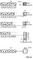
  • FIG. 6 shows the coding of a Coding switch 76, by means of which the address of each sensor 18.22 is set. The assignment is shown for a single, a double, a quadruple and one Eightfold sensor 18.22. Has proven to be particularly suitable a binary switch (mouse piano) with an address length of 1 Bytes (256 addresses) exposed as coding switch 76.
  • the first line of FIG. 6 shows the assignment of the coding switch 76 to a single sensor 18, 22 with a single rocker 78 for a switch function (ON / OFF) and / or for a dimmer function (UP / DOWN).
  • the second line shows the assignment of the coding switch 76 to a double sensor 18, 22 with two rockers, to which the address designated by x in the coding switch 0 "or 1 ".
  • the four rockers are assigned the last two addresses y and x of the coding switch 76 according to the third line.
  • the rocker halves of an eightfold sensor 18, 22 are analogous three addresses x, y, z of the coding switch 76 with those shown Binary codes assigned. It can be seen that each hatched rocker 78 in the four lines of FIG 6 each the one listed in the first line below the coding switch 76 Binary code is assigned. As in the fifth line 6, this binary code is associated with the actuator 20 Assigned switch position "OFF". The position shown of the actuator switch corresponds to the direct assignment in the first installation level. Therefore, each actuator is 20,22 an eight-way coding switch 80. In every actuator 20.22 can also be a serial non-volatile memory (EEPROM) is provided for recording the assigned address be.
  • EEPROM serial non-volatile memory

Landscapes

  • Engineering & Computer Science (AREA)
  • Automation & Control Theory (AREA)
  • Computer Networks & Wireless Communication (AREA)
  • Signal Processing (AREA)
  • Multimedia (AREA)
  • Physics & Mathematics (AREA)
  • General Physics & Mathematics (AREA)
  • Human Computer Interaction (AREA)
  • Selective Calling Equipment (AREA)
  • Small-Scale Networks (AREA)

Abstract

Die Erfindung bezieht sich auf ein Installationssystem (1), insbesondere für eine Hausinstallation, mit einem ein erstes Adernpaar (14a) und ein zweites Adernpaar (14b) aufweisenden Installationsbus (14) sowie mit einem Applikationsbaustein (10). Dieser umfaßt einen Kontaktanschluß (12) zur Spannungsversorgung und eine Anwenderschnittstelle (32) sowie einen Applikationsanschluß (16) für das zweite Adernpaar (14b), an das eine Anzahl von Installationsgeräten (18 bis 24) über jeweils einen Applikationsankoppler (26) anschließar ist. Das Installationssystem (1) kann mittels eines an den Applikationsbaustein (10) anschließbaren Steuerbaustein (30) von einer ersten in eine zweite Installationsebene und darüber hinaus mittels eines Busverbinders (38) zu einer dritten Installationsebene hochgerüstet werden. In der dritten Installationsebene ist dann eine Verknüpfung von programmierbaren Applikations-Funktionen mit Funktionen eines European-Installation-Bus (EIB) möglich. <IMAGE>

Description

Die Erfindung bezieht sich auf ein Installationssystem, insbesondere für eine Hausinstallation.
Ein Installationssystem z. B. im Hausbereich umfaßt ublicherweise ausgehend von einer mit elektrischen Sicherungen versehenen Verteilereinrichtung ein Kabel- oder Leitungssystem zur Verknüpfung einer Vielzahl von Schaltern oder Dimmern (Sensoren) mit einer weiteren Vielzahl von elektrischen Endgeräten (Aktoren), z. B. Leuchten o. dgl.. Ein solches Installationssystem ist allerdings besonders unflexibel hinsichtlich der Systemfunktionalität, zumal eine Zuordnungsänderung zwischen Sensoren und Aktoren sowie eine Nachrüstung zusätzlicher Sensoren und/oder Aktoren nur mit erheblichem Aufwand realisierbar ist. Darüber hinaus ist eine Einbindung eines solchen Installationssystems in das sogenannte European-Installation-Bus-System (instabus EIB) nicht möglich.
Der Erfindung liegt daher die Aufgabe zugrunde, ein besonders flexibles und in einfacher Weise aufrüstbares Installationssystem anzugeben. Dies soll, insbesondere als Untersystem, auch in einen
Figure 00010001
instabus EIB" integrierbar sein.
Diese Aufgabe wird erfindungsgemäß gelöst durch die Merkmale des Anspruchs 1. Vorteilhafte Ausgestaltungen und Weiterbildungen sind Gegenstand der Unteransprüche.
Die Erfindung geht dabei von der Überlegung aus, ein in einfacher und kostengünstiger Art und Weise in ein höheres oder übergeordnetes System, nämlich in das instabus EIB-System, integrierbares Installations-Untersystem zu schaffen, das im wesentlichen Grundfunktionen, wie z. B. Schalten (EIN/AUS), Dimmen (UP/DOWN) oder Jalousie (n WERTE), übernimmt.
Das Installationssystem umfaßt einen Installationsbus in Form zweier Adernpaare einer im European-Installation-Bus-System (EIB-System) genormten Busleitung, wobei das für die Spannungsversorgung (29V DC) vorgesehene zweite Adernpaar für eine räumliche und zahlenmäßige Applikations-Expansion (APX) von Grundfunktionen der Installationstechnik (Schalten, Dimmen, Jalousie) genutzt wird. Die Installation erfolgt zweckmäßigerweise in drei aufeinander aufbauenden Installationsebenen, die sich im wesentlichen hinsichtlich Komfort und Funktionalität unterscheiden. Dabei ist ein Hochrüsten von Ebene zu Ebene bis zu einer Ankopplung an den European-Installation-Bus (EIB) auch in diskreten Zwischenschritten innerhalb derselben Ebene möglich. Die steigende Wertigkeit von Ebene zu Ebene ergibt sich im wesentlichen durch eine Umorganisation von einem dezentralen zu einem zentralen System.
Wahrend die erste Ebene (level I) ein dezentrales stand-alone" System mit direkter Adressierung eines APX-Sensors zu einem APX-Aktor bildet, bilden die zweite Ebene (level II) und die dritte Ebene (level III) jeweils ein zentrales System. Diese unterscheiden sich wiederum dadurch, daß die zweite Ebene ein zentrales stand-alone" System ist, während die dritte Ebene ein zentrales Untersystem des European-Installation-Bus (EIB) ist.
Zentraler Baustein aller drei Ebenen ist ein Applikationsbaustein, an den das zweite Adernpaar des EIB-Installationsbuses als Applikationsbus zum Anschluß einer Anzahl von Installationsgeräten anschließbar ist. Der Applikationsbaustein ist mit einer die Spannungsversorgung führenden zweiten Datenschiene des Installationssystems verbunden und dient in der ersten Ebene lediglich zur Spannungsversorgung der Installationsgeräte. Die Adressierung der Installationsgeräte erfolgt daher auch unabhängig vom Applikationsbaustein, so daß in der ersten Ebene eine getrennte Gruppierung ohne Gruppenüberschneidung vorgesehen ist, z. B. für ein zentrales AUS". Bezüglich der Funktionalität innerhalb der ersten Ebene erfolgt daher eine starre Zuordnung nicht nur zwischen Sensoren und Aktoren, sondern auch innerhalb eines z. B. als Mehrfachschalter ausgebildeten Sensors.
Demgegenüber sind sowohl in der zweiten als auch in der dritten Ebene bezüglich der Funktionalität überschneidende Gruppierungen mit z. B. zentralem AUS" möglich. Zentraler Baustein in der zweiten und dritten Ebene ist ein Steuerbaustein mit einer Anwenderschnittstelle als Schaltzentrale, über den zentral die Adressierung der Sensoren und Aktoren möglich ist. Bei Mehrfachschaltern ist die Wertezuordnung von Sensortasten oder -wippen innerhalb z. B. acht festen Stufen frei wahlbar, wobei jeder Wippenhälfte auch eines Mehrfachschalters eine frei wählbare Funktion zugeordnet werden kann. Darüber hinaus kann bei einem Spannungsausfall der Status eines Aktors gespeichert werden. Die Adressierung und Programmierung der Sensoren und Aktoren erfolgt mittels eines an den Steuerbaustein anschließbaren Computers (PC).
Die dritte Ebene zeichnet sich hinsichtlich der Funktionalität durch eine Verknüpfung der programmierbaren Applikations- oder APX-Funktionen der zweiten Ebene mit EIB-Funktionen aus. Für den Datenaustausch vom und zum European-Installation-Bus ist zwischen den beiden Adernpaaren des Installationbuses ein Busverbinder vorgesehen. Wie auch in der zweiten Ebene sind in der dritten Ebene mehrfache Adressenverknüpfungen möglich, wobei innerhalb der dritten Ebene derartige Verknüpfungen über den Installationsbus auch zwischen APX- und den EIB-Komponenten möglich ist. Die erste und zweite Ebene können jeweils durch Hinzufügen von Komponenten und durch Umprogrammierung zur jeweils nächst höheren Ebene ausgebaut werden.
Der Applikationsbaustein erhalt seine Spannungsversorgung direkt von einer Datenschiene einer Verteilereinrichtung des Installationssystems. Bei Verwendung des EIB-Buskabels ist zweckmäßigerweise dessen zweites Adernpaar an einen am Applikationsbaustein oder Applikationsexpander (APX) vorgesehenen Applikationsanschluß angeschlossen und bildet den Applikationsbus für das oder jedes Installationsgerät. Der Applikationsbaustein enthalt einen Sender und einen Empfänger, die in der ersten Ebene nicht benötigt werden. Zur Aufbereitung der Spannungsversorgung enthalt der Applikationsbaustein außerdem einen Spannungswandler, der als Stromquellenschaltung ausgelegt ist. Um einen Kurzschluß einer im EIB-Bussystem üblicherweise vorgesehenen EIB-Drossel (zweite oder dritte Ebene) zu vermeiden, ist die Anwenderschnittstelle des Applikationsbausteins zweckmäßigerweise vom Applikationsanschluß galvanisch getrennt. Da in der ersten Ebene kein Steuerbaustein vorgesehen ist und somit keine Kommunikation an der Anwenderschnittstelle stattfindet, ist der Sender des Applikationsbausteins in der ersten Ebene automatisch hochohmig.
Der Applikationsankoppler jedes Installationsgerätes, d.h. jedes Sensors und jedes Aktors, umfaßt einen Mikroprozessor und zusätzlich zur Empfangsstufe eine Sendestufe. Der auch das Tastenfeld für die Sensoren und eine Aktor-Endstufe bedienende Mikroprozessor enthält zweckmäßigerweise eine Software für alle Installationsgeräte, d.h. für alle APX-Gerätetypen. Dadurch ist nur eine einzige Programmiermaske für das gesamte Installationssystem zu erstellen. Der Mikroprozessor weist vorzugsweise sowohl einen flüchtigen Speicher (RAM) als auch einen nicht-flüchtigen Speicher (EEPROM) zur Vermeidung eines Adressen- und Kodierverlustes bei einem Spannungsausfall auf.
Um auch eine Fernbedienbarkeit innerhalb des Installationssystems zu ermöglichen, ist mindestens ein mittels eines Infrarot- oder Funk-Senders ansteuerbarer Fernsteuer-Dekoder als Installationsgerät vorgesehen. Der oder jeder Dekoder arbeitet dabei vorteilhafterweise adressen- oder kommandotransparent, so daß dieser keine eigene Adresseneinstellung benötigt. Das Fernsteuersysstem kann uni- oder bidirektional ausgebildet sein, wobei adressentransparente Funk- oder Infrarotsensoren und/oder Funk- oder Infrarotaktoren am Installationsbus angeschlossen sein können. Diese sind dann von fest installierten oder mobilen Sender- bzw. Empfängergeräten ansteuerbar.
Ausführungsbeispiele der Erfindung werden anhand einer Zeichnung näher erläutert. Darin zeigen:
FIG 1
ein Installationssystem einer ersten Ebene,
FIG 2
ein Installationssystem gemäß FIG 1 in einer zweiten Ebene,
FIG 3
ein Installationssystem gemmäß den FIG 1 und 2 in einer dritten Ebene,
FIG 4
ein Blockschaltbild eines Applikationsbaustens,
FIG 5
ein Schaltbild eines Applikationsankopplers eines Sensors oder Aktors und
FIG 6
schematisch einen Kodierschalter zur Adressenzuordnung von Einfach- und Mehrfachsensoren zu einem Aktor.
Einander entsprechende Teile sind in allen Figuren mit den gleichen Bezugszeichen versehen.
FIG 1 zeigt eine erste Installationsebene eines Installationssystems 1 mit in einer Verteilereinrichtung 2 einer ersten Datenschiene 4 und einer zweiten Datenschiene 6 sowie mit einer Spannungsversorgungseinrichtung 8 und mit einem Applikationsexpander (APX) oder Applikationsbaustein 10. Die Spannungsversorgungseinrichtung 8 und der Applikationsbaustein 10 sind jeweils mit der zweiten Datenschiene 6 kontaktiert. Die Datenschienen 4 und 6 sind Teil eines Installationsbuses (Instabus EIB). Die zweite Datenschiene 6 führt eine Gleichspannung Us von 29V DC und dient zur Spannungsversorgung des Applikationsbausteins 10 über dessen Kontaktanschluß 12 zur Datenschiene 6.
Das Installationssysstem 1 umfaßt weiter eine Installationsbusleitung oder ein EIB-Buskabel 14 mit einem ersten Adernpaar 14a für den European-Installation-Bus (EIB) und einem zweiten Adernpaar 14b, das an einen Applikationsanschluß 16 des Applikationsbaustein 6 anschließbar ist. An das zweite Adernpaar 14b sind eine Anzahl von Installationsgeräten angeschlossen, von denen nur einige dargestellt sind. Dargestellt sind ein Sensor 18 und ein Aktor 20 sowie eine Sensor-Aktor-Kombination 22 und ein Fernsteuerdekoder 24. Jedes der Installationsgeräte 18 bis 24 weist einen Applikationsankoppler 26 zur Ankopplung an das zweite Adernpaar 14b des Installationsbuses 14 auf.
Das zweite Adernpaar 14b des Installationsbuses 14 bildet einen seriellen Daten- und Versorgungsbus für die Installationsgeräte 18 bis 24, wobei die Übertragung stets in Richtung vom Sensor 18 zum Aktor 20 stattfindet. Zur Datenübertragung für zu sendende Bit-Informationen wird das zweite Adernpaar 14b des Installationsbuses 14 jeweils kurzgeschlossen (FIG 4).
Bereits in der ersten Installationsebene kann ein eigenständiges Fernsteuersystem auf Hochfrequenz (HF)- und/oder Infrarot (IR)-Basis integriert sein. Dem Fernsteuer-Dekoder 24 ist dann ein mobiler oder stationärer Sender und/oder Empfänger 28 zugeordnet. Wahrend der Dekoder 24 vorzugsweise adressen- oder kommandotransparent arbeitet und demzufolge keine eigene Adresseneinstellung benötigt, werden die Adressen des Sensors 18 und des Aktors 20 sowie der Sensor-Aktor-Kombination 22 bei der Inbetriebnahme des Installationssystems 1 in der ersten Installationsebene fest eingestellt. Der oder jeder Sensor 18 kann ein Ein- oder Mehrfachsensor sein, der in bekannter Weise auf- oder unterputz installiert ist. Ebenso kann der oder jeder Aktor 20 und die oder jede Sensor-Aktor-Kombination 22 ein- oder mehrfach ausgeführt und auf- oder unterputz installiert sein.
Die Funktionalität der ersten Installationsebene entspricht im wesentlichen einem herkömmlichen Installationssystem mit u. a. dem Unterschied, daß nach erfolgter Montage die Zuordnung eines Sensors 18 zu einem Aktor 20, z. B. eines Schalters zu einem Endgerät, bei der Inbetriebnahme frei wählbar festgelegt werden kann. Auch kann der Sensor 18 zur Steuerung mehrerer Aktoren 20,22 verwendet werden, wobei lediglich eine entsprechende Adressierung des Sensors 18 und der entsprechenden Aktoren 20,22 bei der Inbetriebnahme erforderlich ist.
Das Installationssystem gemäß FIG 1 kann hochgerüstet werden auf das Installationssystem 1 gemäß FIG 2, das eine zweite Installationsebene darstellt. In der zweiten Installationsebene - die im wesentlichen der ersten Installationsebene entspricht - ist in der Verteilereinrichtung 2 zusätzlich ein Steuerbaustein 30 vorgesehen, der über eine Anwenderschnittstelle 32 mit dem Applikationsbaustein 10 verbunden ist. Der Steuerbaustein 30 enthält einen Mikroprozessor (MP) sowie damit verbunden einen flüchtigen Speicher (RAM) und einen nicht-flüchtigen Speicher (EEPROM). Der Steuerbaustein 30 ist über einen EIB-Anschluß oder EIB-Busankoppler 33 an der ersten Datenschiene 4 kontaktiert.
Bei der Installation werden der Steuerbaustein 30 und der Applikationsbaustein 10 an der Anwenderschnittstelle 32 zusammengeführt und anschließend gemeinsam auf die Datenschienen 4 und 6 aufgesteckt und dabei kontaktiert. Dabei kann der Steuerbaustein 30 bereits in der zweiten Installationsebene mit der Datenschiene 4 kontaktiert sein. Auch kann bereits in der zweiten Installationsebene eine im European-Installation-Bus (EIB) üblicherweise vorgesehene EIB-Drossel 34 installiert sein.
Im Gegensatz zur ersten Installationsebene, in der ein direkte Adressierung vom Sensor 18, 22 zum Aktor 20, 22 erfolgt, erfolgt in der zweiten Installationsebene die Adressierung der Installationsgeräte 18 bis 24 zentral über den Steuerbaustein 30, an den dazu für die entsprechende Programmierung ein Computer 36 anschließbar ist. Zur Programmierung kann auch in nicht näher dargestellter Art und Weise ein separater Baustein vorgesehen sein, an den dann der Computer 36 anschließbar ist. Bereits in der zweiten Installationsebene sind beliebige Adressenverknüpfungen möglich, wobei die Adressierung der Installationsgeräte 18 bis 24 über das zweite Adernpaar 14b des Buskabels 14 erfolgt.
Das Installationssystem gemäß FIG 2 kann wiederum hochgerüstet werden auf das Installationssystem 1 gemäß FIG 3, das eine dritte Installationsebene darstellt. Diese unterscheidet sich von der zweiten Installationsebene gemäß FIG 2 durch die Einfügung eines Busverbinders 38, der in der Verteilereinrichtung 2 auf die Datenschienen 4 und 6 aufgesetzt wird. Der Busverbinder 38 weist Anschlüsse 40 für das erste Adernpaar 14a des Buskabels 14 auf. In der dritten Installationsebene ist somit zusätzlich eine Verknüpfung von programmierten Applikationsfunktionen gemäß der zweiten Installationsebene mit Funktionen von allen EIB-Anwendungen 42 möglich.
FIG 4 zeigt ein Blockschaltbild des Applikationsbausteins 10, der in allen Installationsebenen vorgesehen ist. Der Applikationsbaustein 10 erhält seine Spannungsversorgung direkt von der zweiten Datenschiene 6. Zur Aufbereitung der Gesamtspannungsversorgung umfaßt der Applikationsbaustein 10 einen Step-down-DC/DC-Spannungswandler 44, der als Stromquellenschaltung ausgelegt ist. Dieser regelt die von der Spannungsversorgungseinrichtung gelieferte Spannung Us = 29V auf eine Spannung Uv von etwa 12V herunter, wobei dessen Begrenzungsstrom - auf den Primärkreis berechnet - etwas unter dem maximalen Strom einer EIB-Spannungsversorgung liegen sollte. Damit wird vermieden, daß diese nicht im Bit-Kurzschluß mit deren Begrenzung anspricht. Der Spannungswandler 44 weist zusätzlich einen +5V-Ausgang 45 auf.
Da der Spannungswandler 44 eine Stromquelle zur Strombegrenzung bildet, kann die Datenübertragung über das zweite Adernpaar 14b dadurch erfolgen, daß dieser für zu sendende Bit-Informationen jeweils kurzgeschlossen wird. Entsprechend ist die Spannungsversorgung in jedem Installationsgerät 18 bis 24 gepuffert, so daß im Bit-Übertragungsmoment keine Unterbrechung stattfindet. Um die Spannungsversorgung aufrecht zu erhalten, sollte der Datendurchsatz jedoch einen bestimmten Wert nicht überschreiten. Aus diesem Grund sind sehr kurze Datentelegramme vorgesehen, die jedoch die Grundfunktionen vollständig bedienen können. Die Sicherstellung der Spannungsversorgung ist mit sogenannten Sende-Zeitverzügen nach erfolgten Telegrammen zusätzlich optimierbar. Bei einem derartigen Sendeverfahren mit Zeitaufschub bei einer Busbelegung und anschließender Prioritätssteuerung über das Zufallsprinzip und/oder proportional zu dem Digitalwert der eingestellten Adresse ermöglicht eine Speicherung eines Sendesignals im Sensor 18,22 bis zur Busfreigabe.
Der Applikationsanschluß 16 zum Anschluß des zweiten Adernpaares 14b des Buskabels 14 enthält einen Sender 46 und einen Empfänger 48. Der über einen Widerstand 50 und eine Leuchtdiode 52 gegen Masse geschaltete Sender 46 und der Empfänger 48 sind über einen Reset-Schalter 54 mit dem Spannungswandler 44 verbunden. Die Anwenderschnittstelle 32 des Applikationsbausteins 10 ist mit einer galvanischen Trennung 56 versehen, um einen Kurzschluß der EIB-Drossel 34 zu verhindern. Über diese Anwenderschnittstelle 32 ist in der zweiten und dritten Installationsebene der Steuerbaustein 30 mit dem Applikationsbaustein 10 verbunden. Lediglich in der ersten Installationsebene, in der kein Steuerbaustein 30 vorgesehen ist, findet keine Kommunikation an der Anwenderschnittstelle 32 statt, so daß der Sender 46 automatisch hochohmig ist.
FIG 5 zeigt ein Schaltbild der Applikationsankopplung 26, die in jedem Installationsgerät 18 bis 24 vorgesehen ist. Über einen Busanschluß 58 für das zweite Adernpaar 14b werden sowohl Daten als auch die Spannungsversorgung Uv vom Applikationsbaustein 10 geführt. Mittels eines Linearreglers 60 wird die Versorgungsspannung Uv auf eine Spannung Up für einen Mikroprozessor 62 heruntergeregelt. Die Spannung Up sollte um etwa 1V oberhalb von +5V liegen, um einerseits Spannungsabfälle entlang einer Buslinie abzufangen, und um andererseits genügend Energie in einem Pufferkondensator C3 zu speichern. Dadurch wird vermieden, daß auch bei ungünstigen Folgen von Bit-Kurzschlüssen die Spannung Up für den Mikroprozessor 62 zusammenbricht.
Der Mikroprozessor 62 weist einen Eingang 64 für Signale vom Sensor 18,22 auf. Ein Ausgang 66 des Mikroprozessors 62 dient zum Anschluß an den Aktor 20,22. Zum Umschalten von Mehrfach-Sensoren 18,22 und Mehrfach-Aktoren 20,22 ist ein Anschluß 68 am Mikroprozessor 62 vorgesehen. Ein weiterer Ausgang 70 des Mikroprozessors 62 dient zum Anschluß an einen Adress-Kodierschalter (76 in FIG 6). Ein Empfängereingang 72 des Mikroprozessors 62 ist über einen Widerstand R1 mit dem Linearregler 60 verbunden. Der Empfängereingang 72 führt über einen Transistor T1 und eine Zenerdiode D1 sowie einen Widerstand R4 an den Busanschluß 58. Die Zenerdiode D1 ist anodenseitig über einen Widerstand R2 und kathodenseitig über einen Kondensator C2 gegen Masse geschaltet. Der Transistor T1 bildet zusammen mit der Zenerdiode D1, dem Kondensator C2 sowie den Widerständen R2 und R4 eine Empfangsstufe des Applikationsankopplers 26, wobei die Zenerdiode D1 eine die Eingangsempfindlichkeit bestimmende Triggerschwelle setzt.
Ein Senderausgang 74 des Mikroprozessors 62 ist über ein RC-Glied mit dem Kondensator C1 und dem Widerstand R1 an die Basis eines Transistors T2 angeschlossen, der kollektorseitig mit dem Busanschluß 58 verbunden ist. Ebenso wie der Empfänger-Transistor T1 ist auch der Sende-Transistor T2 emitterseitig gegen Masse geschaltet. Eine anodenseitig gegen Masse geschaltete Diode D2 und ein ebenfalls gegen Masse geschalteter Widerstand R6 sind mit der Basis des Transistors T2 verbunden. Eine anodenseitig gegen Masse geschaltete Zenerdiode D4 ist katodenseitig mit dem Kollektor des Transistors T2 vebunden. Die Zenerdiode D4 sichert den Verpolungsschutz für die aus dem Transistor T2, dem Kondensator C1, den Dioden D2 und D4 sowie den Widerständen R1 und R6 aufgebaute Sendestufe des Applikationsankopplers 26. Dieser schließt bei einer bestimmten Bit-Information während der Bit-Zeit das zweite Adernpaar 14b kurz, wobei dem Kurzschluß die 1" oder 0" zuordenbar ist. Der Kondensator C1 und die Diode D2 verhindern bei einem Außertrittgeraten des Mikroprozessors 62 einen Kurzschluß des zweiten Adernpaares 14b und damit des Installationsbuses 14. Während der Applikationsankoppler 26 beim Sensor 18,22 zur Kollisionserkennung sowohl die Sende- als auch die Empfangsstufe enthält, ist bei dem oder jedem Aktor 20,22 lediglich die Empfangsstufe erforderlich.
Der Mikroprozessor 62 des Applikationsankopplers 26 ist vorzugsweise ein maskenprogrammierbarer Standard-Mikroprozessor, der das Tasten- oder Wippenfeld für den oder jeden Sensor 18,22 und die (nicht dargestellte Endstufe) des oder jedes Aktors 20,22 direkt bedient. Der Mikroprozessor 62 kann die Software für alle bereitgestellten Typen von Installationsgeräten enthalten, so daß lediglich eine einzige Programmiermaske für das gesamte Installationssystem zu erstellen ist.
FIG 6 zeigt an einem Zuordnungsbeispiel die Kodierung eines Kodierschalters 76, mittels dem die Adresse jedes Sensors 18,22 eingestellt wird. Dargestellt ist die Zuordnung für einen Einfach-, einen Zweifach-, einen Vierfach- und einen Achtfach-Sensor 18,22. Als besonders geeignet hat sich ein Binärschalter (Mäuseklavier) mit einer Adresslänge von 1 Byte (256 Adressen) als Kodierschalter 76 herausgestellt.
Die erste Zeile der FIG 6 zeigt die Zuordnung des Kodierschalters 76 zu einem Einfach-Sensor 18,22 mit einer einzelnen Wippe 78 für eine Schalter-Funktion (EIN/AUS) und/oder für eine Dimmer-Funktion (UP/DOWN). Die zweite Zeile zeigt die Zuordnung des Kodierschalters 76 zu einem ZweifachSensor 18,22 mit zwei Wippen, denen die im Kodierschalter mit x bezeichnete Adresse 0" bzw. 1" zugeordnet ist. Analog sind bei einem Vierfach-Sensor 18,22 gemäß der dritten Zeile den vier Wippen die letzten beiden Adressen y und x des Kodierschalters 76 zugeordnet. Dabei ist den Wippenhälften der vier Wippen des Sensors 18,22 der dargestellte Binärcode (x = 0 und y = 0, x = 1 und y = 0, x = 0 und y = 1 bzw. x = 1 und y = 1) zugeordnet.
Analog sind den Wippenhälften eines Achtfach-Sensor 18,22 drei Adressen x,y,z des Kodierschalters 76 mit den dargestellten Binärcodes zugeordnet. Man erkennt, daß der jeweils schraffierten Wippe 78 in den vier Zeilen der FIG 6 jeweils der in der ersten Zeile unterhalb des Kodierschalters 76 aufgeführte Binärcode zugeordnet ist. Wie in der fünften Zeile der FIG 6 angedeutet, ist dieser Binärcode dem Aktor 20 mit Schalterstellung "AUS" zugeordnet. Die dargestellte Stellung des Aktorschalters entspricht der direkten Zuordnung in der ersten Installationsebene. Daher ist jeder Aktor 20,22 mit einem Achtfach-Kodierschalter 80 ausgerüstet. In jedem Aktor 20,22 kann auch ein serieller nicht flüchtiger Speicher (EEPROM) zur Aufnahme der zugeordneten Adresse vorgesehen sein.

Claims (9)

  1. Installationssystem mit einem Installationsbus (1) mit einem ersten Adernpaar (14a) und mit einem zweiten Adernpaar (14b) sowie mit einem Applikationsbaustein (10), der einen Kontaktanschluß (12) zur Spannungsversorgung und eine Anwenderschnittstelle (32) sowie einen Applikationsanschluß (16) für das zweite Adernpaar (14b) aufweist, an das eine Anzahl von Installationsgeräten (18 bis 24) über jeweils einen Applikationsankoppler (26) anschließbar ist.
  2. Installationssystem nach Anspruch 1, mit einem einen programmierbaren Prozessor (MP) und einen nicht-flüchtigen Speicher (EEPROM) aufweisenden Steuerbaustein (30), der an den Applikationsbaustein (10) anschließbar ist.
  3. Installationssystem nach Anspruch 2, mit einem Busverbinder (38) vom ersten Adernpaar (14a) zum zweiten Adernpaar (14b).
  4. Installationssystem nach einem der Ansprüche 1 bis 3, wobei der Applikationsbaustein (10) einen Spannungswandler (44) in Stromquellenschaltung und eine vorzugsweise galvanische Trenneinrichtung (56) zwischen der Anwenderschnittstelle (32) und dem Applikationsanschluß (16) umfaßt.
  5. Installationssystem nach einem der Ansprüche 1 bis 4, wobei der Applikationsbaustein (10) einen Sender (46) und einen Empfänger (48) umfaßt.
  6. Installationssystem nach einem der Ansprüche 1 bis 5, wobei der oder jeder Applikationsankoppler (26) einen Mikroprozessor (62) und zusätzlich zu einer Empfangsstufe (T1) eine Sendestufe (T2) umfaßt.
  7. Installationssystem nach einem der Ansprüche 1 bis 6, wobei der Applikationsankoppler (26) einen Linearregler (60) zur Spannungsreglung aufweist.
  8. Installationssystem nach einem der Ansprüche 1 bis 7, wobei mindestens ein Sensor (18,22) und mindestens ein Aktor (20,22) als Installationsgeräte vorgesehen sind.
  9. Installationssystem nach einem der Ansprüche 1 bis 8, wobei als Installationsgerät mindestens ein mittels Infrarot oder Funk ansteuerbarer Fernsteuer-Dekoder (24) vorgesehen ist.
EP97116301A 1996-09-30 1997-09-18 Installationssystem Withdrawn EP0833426A3 (de)

Applications Claiming Priority (2)

Application Number Priority Date Filing Date Title
DE19640300 1996-09-30
DE19640300A DE19640300A1 (de) 1996-09-30 1996-09-30 Installationssystem

Publications (2)

Publication Number Publication Date
EP0833426A2 true EP0833426A2 (de) 1998-04-01
EP0833426A3 EP0833426A3 (de) 1999-08-04

Family

ID=7807444

Family Applications (1)

Application Number Title Priority Date Filing Date
EP97116301A Withdrawn EP0833426A3 (de) 1996-09-30 1997-09-18 Installationssystem

Country Status (2)

Country Link
EP (1) EP0833426A3 (de)
DE (1) DE19640300A1 (de)

Cited By (10)

* Cited by examiner, † Cited by third party
Publication number Priority date Publication date Assignee Title
WO1999048186A1 (de) * 1998-03-19 1999-09-23 Robert Bosch Gmbh Netzwerkankopplungsvorrichtung und -verfahren
WO2001020748A1 (de) * 1999-09-14 2001-03-22 Siemens Aktiengesellschaft Verfahren zum betreiben eines gebäude-installationssystems
DE19945337A1 (de) * 1999-09-22 2001-03-29 Volkswagen Ag System mit busfähigen Teileinheiten
WO2001065324A1 (de) * 2000-03-01 2001-09-07 Siemens Aktiengesellschaft Verfahren und vorrichtung zum verarbeiten von daten eines automatisierungssystems für eine anlage der gebäudesystemtechnik
WO2001024451A3 (de) * 1999-09-30 2001-10-11 Siemens Ag Verfahren zur umsetzung einer fernsteuerung
WO2002014963A3 (de) * 2000-08-11 2002-08-15 Siemens Ag Verfahren sowie verarbeitungssystem zur ermittlung der räumlichen struktur eines steuerungssystems
EP0993094A3 (de) * 1998-10-06 2003-08-06 Insta Elektro GmbH Elektrisches Installationssystem
CN100373852C (zh) * 2002-09-28 2008-03-05 株式会社Kt 使用高级非对称数字用户线路的家庭自动化通信系统
EP1993040A1 (de) * 2007-05-12 2008-11-19 Abb Ag Sensoreinheit mit mehreren Bedien-oder Funktionselementen
WO2015110588A3 (de) * 2014-01-23 2015-09-17 Lingg & Janke Ohg Bussystem sowie verfahren zum betreiben eines bussystems

Families Citing this family (4)

* Cited by examiner, † Cited by third party
Publication number Priority date Publication date Assignee Title
DE10327504B4 (de) * 2003-06-17 2007-05-03 Theben Ag Multifunktionsgerät
DE102004021679B4 (de) * 2004-04-29 2007-10-11 Josef Gerhard Geier Elektroinstallationsanordnung
DE102004023201B4 (de) * 2004-05-11 2006-05-11 Siemens Ag Sensoreinrichtung zum Erfassen der Schaltstellung einer schaltbaren Kontaktstelle
DE102005002752B4 (de) * 2005-01-20 2008-03-27 Siemens Ag Spannungsversorgungsvorrichtung für ein Busgerät sowie Busgerät

Family Cites Families (3)

* Cited by examiner, † Cited by third party
Publication number Priority date Publication date Assignee Title
DE4430441C2 (de) * 1993-09-02 1996-07-18 Reinhard Reimund Vorrichtung zur Steuerung von elektrischen Verbrauchern
DE4432745C1 (de) * 1994-09-14 1996-03-21 Zangenstein Elektro Verfahren für den Betrieb einer Speicherheizgerätesteuerung
DE19501489A1 (de) * 1995-01-19 1996-07-25 Abb Patent Gmbh Verfahren und Einrichtung zur Informationsübertragung im Europäischen Installationsbussystem EIB

Non-Patent Citations (2)

* Cited by examiner, † Cited by third party
Title
RIS H.R.: "Eib- UN SYSTEME DE BUS UNIFIE POUR INSTALLATIONS ELECTRIQUES", BULLETIN SEV VSE 7 96, 29 March 1996 (1996-03-29), pages 31 - 37, XP000612698 *
RÜTIMANN P.: "Mit Bussystemen gegen den Leitungswirrwarr", BULLETIN SEV VSE 7 96, 29 March 1996 (1996-03-29), DEUTSCHLAND, pages 43 - 49, XP000615044 *

Cited By (11)

* Cited by examiner, † Cited by third party
Publication number Priority date Publication date Assignee Title
WO1999048186A1 (de) * 1998-03-19 1999-09-23 Robert Bosch Gmbh Netzwerkankopplungsvorrichtung und -verfahren
EP0993094A3 (de) * 1998-10-06 2003-08-06 Insta Elektro GmbH Elektrisches Installationssystem
WO2001020748A1 (de) * 1999-09-14 2001-03-22 Siemens Aktiengesellschaft Verfahren zum betreiben eines gebäude-installationssystems
DE19945337A1 (de) * 1999-09-22 2001-03-29 Volkswagen Ag System mit busfähigen Teileinheiten
WO2001024451A3 (de) * 1999-09-30 2001-10-11 Siemens Ag Verfahren zur umsetzung einer fernsteuerung
WO2001065324A1 (de) * 2000-03-01 2001-09-07 Siemens Aktiengesellschaft Verfahren und vorrichtung zum verarbeiten von daten eines automatisierungssystems für eine anlage der gebäudesystemtechnik
WO2002014963A3 (de) * 2000-08-11 2002-08-15 Siemens Ag Verfahren sowie verarbeitungssystem zur ermittlung der räumlichen struktur eines steuerungssystems
US7814187B2 (en) 2000-08-11 2010-10-12 Siemens Aktiengesellschaft Method and processing system for determining the spatial structure of a control system
CN100373852C (zh) * 2002-09-28 2008-03-05 株式会社Kt 使用高级非对称数字用户线路的家庭自动化通信系统
EP1993040A1 (de) * 2007-05-12 2008-11-19 Abb Ag Sensoreinheit mit mehreren Bedien-oder Funktionselementen
WO2015110588A3 (de) * 2014-01-23 2015-09-17 Lingg & Janke Ohg Bussystem sowie verfahren zum betreiben eines bussystems

Also Published As

Publication number Publication date
EP0833426A3 (de) 1999-08-04
DE19640300A1 (de) 1998-04-02

Similar Documents

Publication Publication Date Title
DE69331927T2 (de) Rechnergesteuerte schalteranordnung mit identifikationsschaltung
DE69724584T2 (de) Beleuchtungssteuerung
DE19640300A1 (de) Installationssystem
WO1999048251A1 (de) Verfahren zum inbetriebnehmen eines bussystems sowie entsprechendes bussystem
EP0790541A2 (de) Anschlusseinrichtung für ein elektrisches Installationssystem
EP0776108A2 (de) Bussystem, insbesondere zur elektrischen Installation
EP0402654B1 (de) Anschlussvorrichtung für den Anschluss elektrischer Verbraucher
DE3008450C2 (de) Sequentielles Übertragungssystem zum adressenlosen Anschließen mehrerer Teilnehmer an eine Zentrale
EP3925039A1 (de) Verfahren zum betrieb eines stromverteilers
DE19610381C2 (de) Installationsbussystem für eine Stromschienenbeleuchtung
DE19645626B4 (de) Busgerät für den Anschluss an ein Bussystem der Gebäudesystemtechnik
WO2011076387A2 (de) Elektrisches installationssystem
EP0791871B1 (de) Schalteranordnung zur An- und Abschaltung der elektrischen Energiezufuhr von elektrischen Verbrauchern
EP1993010B1 (de) Sensoreinheit
EP1289217B1 (de) Kommunikation mittels Wechselstromhalbwellen
DE4407895C2 (de) Verfahren zur Konfiguration eines Informationsdatennetzes
EP2390985A2 (de) Verfahren zum Betreiben eines elektrischen Installationssystems umfassend eine Hauptstelle und eine daran angeschlossene Nebenstelle
DE19619175B4 (de) Anordnung zur Erzeugung von Lichtszenen
WO2010048987A1 (de) Gerät für eine lampenanwendung, verfahren zur kommunikation zwischen geräten
DE10312183A1 (de) Gebäudeinstallationssystem
EP0874343A2 (de) System zur komfortablen, mobilen Bedienung, Überwachung und zum Datenaustausch
DE102007022342B4 (de) Sensoreinheit mit mehreren Bedien- oder Funktionselementen
DE19927869C1 (de) Elektroinstallationseinrichtung für Gebäude
DE102020126367B4 (de) Verfahren zum gemeinsamen Ein- und Ausschalten von elektrischen Verbrauchern sowie elektrische Installation
DE4221456A1 (de) Betaetigungsanordnung

Legal Events

Date Code Title Description
PUAI Public reference made under article 153(3) epc to a published international application that has entered the european phase

Free format text: ORIGINAL CODE: 0009012

AK Designated contracting states

Kind code of ref document: A2

Designated state(s): DE FR IT

PUAL Search report despatched

Free format text: ORIGINAL CODE: 0009013

AK Designated contracting states

Kind code of ref document: A3

Designated state(s): AT BE CH DE DK ES FI FR GB GR IE IT LI LU MC NL PT SE

17P Request for examination filed

Effective date: 20000202

AKX Designation fees paid

Free format text: DE FR IT

17Q First examination report despatched

Effective date: 20040819

STAA Information on the status of an ep patent application or granted ep patent

Free format text: STATUS: THE APPLICATION IS DEEMED TO BE WITHDRAWN

18D Application deemed to be withdrawn

Effective date: 20100401