EP0833461A1 - Dispositif de réception avec diversité de polarisation pour systèmes de communication basés sur des trames - Google Patents
Dispositif de réception avec diversité de polarisation pour systèmes de communication basés sur des trames Download PDFInfo
- Publication number
- EP0833461A1 EP0833461A1 EP96115498A EP96115498A EP0833461A1 EP 0833461 A1 EP0833461 A1 EP 0833461A1 EP 96115498 A EP96115498 A EP 96115498A EP 96115498 A EP96115498 A EP 96115498A EP 0833461 A1 EP0833461 A1 EP 0833461A1
- Authority
- EP
- European Patent Office
- Prior art keywords
- receiving
- devices
- receiving station
- station according
- antenna
- Prior art date
- Legal status (The legal status is an assumption and is not a legal conclusion. Google has not performed a legal analysis and makes no representation as to the accuracy of the status listed.)
- Granted
Links
- 230000010287 polarization Effects 0.000 title claims description 36
- 238000010295 mobile communication Methods 0.000 title claims description 13
- 238000011156 evaluation Methods 0.000 claims abstract description 5
- 230000005540 biological transmission Effects 0.000 claims description 7
- 239000000654 additive Substances 0.000 claims description 3
- 230000000996 additive effect Effects 0.000 claims description 3
- 238000012360 testing method Methods 0.000 claims description 2
- 125000004122 cyclic group Chemical group 0.000 abstract 1
- 238000000034 method Methods 0.000 description 10
- 238000004891 communication Methods 0.000 description 7
- 238000005259 measurement Methods 0.000 description 2
- 238000012935 Averaging Methods 0.000 description 1
- 230000001413 cellular effect Effects 0.000 description 1
- 238000001514 detection method Methods 0.000 description 1
- 230000006866 deterioration Effects 0.000 description 1
- 238000011161 development Methods 0.000 description 1
- 238000004519 manufacturing process Methods 0.000 description 1
- 230000028161 membrane depolarization Effects 0.000 description 1
- 238000012545 processing Methods 0.000 description 1
- 230000001681 protective effect Effects 0.000 description 1
- 230000005855 radiation Effects 0.000 description 1
- 238000000926 separation method Methods 0.000 description 1
- 230000036962 time dependent Effects 0.000 description 1
Images



Classifications
-
- H—ELECTRICITY
- H04—ELECTRIC COMMUNICATION TECHNIQUE
- H04B—TRANSMISSION
- H04B7/00—Radio transmission systems, i.e. using radiation field
- H04B7/02—Diversity systems; Multi-antenna system, i.e. transmission or reception using multiple antennas
- H04B7/10—Polarisation diversity; Directional diversity
Definitions
- the invention relates to a receiving station for frame-oriented Mobile communication systems.
- a mobile communication system sees, for example, a time division multiplex method for a radio interface, the ones to be transmitted Data in radio blocks - frames - are organized and a frame of a time slot or a plurality of time frames corresponds.
- Mobile communication systems enable communication connections to be established to mobile subscribers by providing information are transmitted via a radio interface. are multiple participants on the same carrier frequency this Radio interface separated by different time slots, there is a time division multiplex mobile communication system.
- the Time division multiplexing is also called TDMA (Time Division Multiple Access) method.
- TDMA Time Division Multiple Access
- Such a mobile communication system is for example the well-known digital GSM mobile radio system.
- the Radio interface also other methods for separating the Participants are applied.
- a frequency division multiplex is offered, It may differ in the procedures for separating the participants however, it can also be a code division multiplex (CDMA) method.
- CDMA code division multiplex
- the mobile communication system can be used as a digital one Frequency division multiplex communication system, in which the data to be transferred is in a frame-oriented Data structure are organized.
- the transmitted information on the radio interface various disorders. That from a broadcasting station sent information reaches a receiving station via different propagation paths, so that at the receiving station the signal components of different propagation paths overlay.
- shadowing can prevent the transmission of Information from a sending station to the receiving station significantly hinder. Also interference in the frequency band of the radio interface lead to a deterioration in quality of the received signals.
- the preferred direction of polarization in mobile radio is Vertical polarization.
- This polarization level is cheaper than a horizontal one, since most reflectors also have one Have vertical structure, resulting in low depolarization occurs with such a reflection.
- the horizontal Level measured up to 20 dB weaker signal becomes. That is, despite reflections in built-up areas Vertical component dominant in the received signal. In areas with Vegetation, the reflection is much more diffuse.
- Measurements in the Horizontal plane gave one under such conditions Reception level, which is only slightly lower than in the vertical plane. The basis of this measurement is a vertical one arranged antenna of the moving mobile station.
- Handheld devices are used by the Users in any hand position, sitting or standing position utilized.
- the preferred polarization level of the handheld can change during use. Consequently there is no defined preferred polarization of the mobile station. This can cause variations in the reception field strength of up to 20 dB occur.
- the polarization level of the base station antenna is usually vertical polarization.
- German patent application 196 17 140.7 it is known from German patent application 196 17 140.7, to improve reception facilities for polarization diversity to use.
- Two antennas different Polarization provide a receiving station with received signals, by the different polarization are at least partially decorrelated. The receiving station can then make a selection from the received signals. In such a configuration of a receiving station however, a high level of reception facilities for everyone possible reception branch can be operated.
- the invention is therefore based on the object of a receiving station with improved tracking of the polarization direction specify. This task is performed by the receiving station solved according to the features of claim 1. Advantageous refinements are in the subclaims remove.
- the receiving station for frame-oriented mobile communication systems has at least two, preferably three or more, antenna devices different Polarization directions, at least two with different Receiving devices connected to antenna devices for emitting processed reception signals, at least a combiner for generating a sum signal from the Receive signals, an evaluation device for evaluating the Sum signal and a control device for such Control the connection of the receiving devices with the Antenna devices that the worse quality Receiving device emitting the reception signal cyclically with other antenna devices is connected.
- Polarization scanning is carried out by this receiving station possible because a receiving device can be used to cyclically more antenna devices of different Sensing polarization, which may be a qualitative received better reception signal.
- this receiving device connected to an antenna device, and a Comparison of this received signal with the previously selected one Received signal carried out.
- the qualitatively better received signal if necessary with the addition of further reception signals processed in the combiner to generate a sum signal and fed to an evaluation device for further evaluation.
- the "Scanning" receiving device receives a receiving signal with better quality than the best receiving signal up to then, the now best receiving signal is held on this receiving device and is not further scanned with this receiving device. This in turn releases a receiving device which again shows the different polarization directions on the remaining antenna devices can scan.
- the signal / noise ratio and / or the ratio of carrier signal to interference signal is used will. This is done accordingly, for example a development of the invention in a device for Assess the quality of the received signals. This facility can be used both in the combiner and in the control unit will be realized. The signal level can also be qualitative Assessment to be evaluated.
- the combination device a selection of the qualitative better reception signals or generates the sum signal through an additive combination of at least two received signals.
- the additive linking of the received signals takes place advantageously by amount and phase.
- connection of the receiving devices with the antenna devices advantageously takes place via switching devices, which correspond to the frame structure of the mobile communication system be switched. Be further the timeslots of a time division multiplexing process than the frames viewed without restricting the generality of the invention. I.e. switching the signal path with the best quality takes place during the protective distances between two time slots, which affects the reception quality is kept low by switching faults. While The protection time between two time slots is usually set to the transmission side reduces the radiated power.
- each of the switching devices can the connection from a receiving device to manufacture each antenna device. So it is possible with a small set of antenna devices, for example get along three or four by all for example, two receiving devices can be used can.
- the cyclical scanning of the receiving device with qualitative poorer reception signal is preferably time-dependent, during the protection period between two time slots.
- the Invention becomes a statement about the quality of the received signal only after observing a certain period of time met. For example, by averaging the signal / noise ratio or by specifying the bit error rate for one Radio block is a test variable for assessing the quality of the received signal.
- a decorrelation between the antenna devices can also be achieved by spatially are separated. At least individual antenna devices therefore do not have a common geometric center, but are separated by a certain distance.
- the influence of polarization diversity is therefore a Room diversity reception possible. With the help of space diversity this advantageous embodiment may result in a negative Counteracted multi-way influence.
- the control device also to control the connection between the Transmitting devices and the antenna devices are provided is. This means that the radiation from one Radio station containing receiving station to an improved Polarization direction is adjustable.
- control device not just between several fixed ones Antenna devices of different polarization switched but that these antenna devices different polarization set electronically will.
- control device by electronically adjusting the direction of polarization an antenna device causes that with the antenna device connected receiving device receive signals different polarization directions are supplied.
- a physical antenna device can therefore have multiple antenna devices realize in the sense of the invention. In order to however, there is an increased control effort.
- the mobile communication system shown in FIG. 1 is a well-known GSM mobile radio system, which consists of a variety of Mobile switching centers MSC exists, which are networked with each other are or establish access to a landline PSTN. Furthermore, these mobile switching centers are each with MSC connected to at least one base station controller BSC. Each base station controller BSC in turn enables one Connection to at least one base station BS.
- Base station BS is a radio station that uses a radio interface a communication link to mobile stations MS can build up. Such a radio connection is an example in FIG to a mobile station MS.
- the radio interface between base station BS and mobile station MS is organized according to the time division method. For example, eight on a carrier frequency Time slots provided for different communication links and to organize the radio interface can be used. Provides a base station too several carrier frequencies available, there is also a frequency division multiplex in front.
- the communication link between base station BS and Mobile station MS is subject to multipath propagation, which through reflections, for example on buildings or plantings in addition to the direct path of propagation will. If one assumes a movement of the mobile station MS, then the multipath propagation leads along with others Faults in that at the receiving base station BS, in called another receiving station, the signal components of the different propagation paths of different polarization directions overlay over time and cause wiping is coming.
- a receiving station can according to the invention Significantly improve reception at the receiving station.
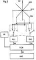
- To this receiving station consists, for example, of four antenna devices AE1 to AE4 by their shape and / or Arrangement have different directions of polarization. For example, the directions of polarization of the antenna devices AE1 to AE4 rotated by 45 degrees to each other. When choosing the polarization directions is important to ensure that with a small number of antenna devices the greatest possible decorrelation of the received signals compared to the other antenna devices remains.
- the receiving station also contains two receiving devices RX1 and RX2, each with a switch S are connected. These switches S can be the respective Receiving device RX1, RX2, each with one of the four Connect antenna devices AE1 to AE4. The switches S are controlled by a control device SE.
- the receiving devices RX1, RX2 are those of the Antenna devices AE1 to AE4 signals recorded processed. This preparation consists, for example, of that these signals are transmitted in the baseband. Consequently give the receiving devices RX1 and RX2 receive signals it off.
- These received signals are from a combiner KOM recorded and processed into a sum signal ss.
- This Processing can consist, for example, that the better quality received signal it is selected, or an addition according to the amount and phase of both received signals to the sum signal ss. It can also other commonly known methods of linking multiple signals can be applied.
- the sum signal ss evaluated what, for example, equalization and signal detection in the baseband corresponds to a GSM receiving station.
- the control device SE has a connection to the combiner KOM on, which makes it possible for the control device SE to Control switch S so that the poor quality Receiving signal it receiving device, for example RX1, cyclically with other antenna devices AE1 to AE3 is connected.
- the cycle can be constant Intervals concern or e.g. depending on the transmission conditions be adjustable.
- the second receiving device RX2 connected to the fourth antenna device AE4 and receives a signal from this antenna device AE4 that it can process it to the best quality reception signal. For example, by a facility for evaluating the Quality of the received signals in the COM combiner is established that during the cyclical Scanning the first receiving device RX1 through it qualitatively better received signal it is emitted (in FIG 2 of antenna device AE3), so during the next Guard time between two time slots, the dominant signal path can be switched to the first receiving device RX1. In As a result, the second receiving device RX2 takes over the task polarization scanning, in turn by cyclically remaining antenna devices AE1, AE2 and AE4 with this second receiving device RX2 are connected.
- the scanning switch S is switched during protection periods between two time slots.
- FIG 3 shows a receiving station opposite the receiving station was modified in accordance with FIG 2 that the Antenna devices AE1 and AE3 compared to the antenna devices AE2 and AE4 are spatially separated.
- the spatial Separation can be characterized in that the geometric centers of the antenna devices are not agree, but are separated by a distance d.
- the operation of this receiving station in relation to the Switching and evaluating the signals is equivalent to that previously described procedures.
- FIG 4 shows an exemplary base station BS which the Receiving station according to FIG 3 includes and additional transmitters TX1 and TX2 includes.
- the one described so far Receiving case is now extended to the transmission case, so that the Antenna devices AE1 to AE4 not only with the receiving devices RX1, RX2, but also with the transmitters TX1, TX2 can be connected. This connection is made via duplexers DX1 and DX2.
- the control device SE is designed in accordance with FIG. that with knowledge of those determined for the reception case cheapest polarization direction or the corresponding one Antenna device AE3, AE4, this antenna device AE3, AE4 is also used for the transmission case. For a communication link thus becomes the same antenna device AE3, AE4 both for receiving, as well used for sending.
Landscapes
- Engineering & Computer Science (AREA)
- Computer Networks & Wireless Communication (AREA)
- Signal Processing (AREA)
- Radio Transmission System (AREA)
- Mobile Radio Communication Systems (AREA)
- Radio Relay Systems (AREA)
- Radar Systems Or Details Thereof (AREA)
Priority Applications (5)
| Application Number | Priority Date | Filing Date | Title |
|---|---|---|---|
| EP96115498A EP0833461B1 (fr) | 1996-09-26 | 1996-09-26 | Dispositif de réception avec diversité de polarisation pour systèmes de communication basés sur des trames |
| AT96115498T ATE195041T1 (de) | 1996-09-26 | 1996-09-26 | Empfangseinrichtung mit polarisationsdiversity für rahmenorientierte mobilkommunikationssysteme |
| DE59605655T DE59605655D1 (de) | 1996-09-26 | 1996-09-26 | Empfangseinrichtung mit Polarisationsdiversity für rahmenorientierte Mobilkommunikationssysteme |
| CA002216342A CA2216342A1 (fr) | 1996-09-26 | 1997-09-24 | Station de reception pour systeme de communication mobile a trames. |
| IDP973279A ID18490A (id) | 1996-09-26 | 1997-09-25 | Stasiun penerima untuk sistem komunikasi berpindah terorientasi kepada bingkai |
Applications Claiming Priority (1)
| Application Number | Priority Date | Filing Date | Title |
|---|---|---|---|
| EP96115498A EP0833461B1 (fr) | 1996-09-26 | 1996-09-26 | Dispositif de réception avec diversité de polarisation pour systèmes de communication basés sur des trames |
Publications (2)
| Publication Number | Publication Date |
|---|---|
| EP0833461A1 true EP0833461A1 (fr) | 1998-04-01 |
| EP0833461B1 EP0833461B1 (fr) | 2000-07-26 |
Family
ID=8223228
Family Applications (1)
| Application Number | Title | Priority Date | Filing Date |
|---|---|---|---|
| EP96115498A Expired - Lifetime EP0833461B1 (fr) | 1996-09-26 | 1996-09-26 | Dispositif de réception avec diversité de polarisation pour systèmes de communication basés sur des trames |
Country Status (5)
| Country | Link |
|---|---|
| EP (1) | EP0833461B1 (fr) |
| AT (1) | ATE195041T1 (fr) |
| CA (1) | CA2216342A1 (fr) |
| DE (1) | DE59605655D1 (fr) |
| ID (1) | ID18490A (fr) |
Cited By (1)
| Publication number | Priority date | Publication date | Assignee | Title |
|---|---|---|---|---|
| WO2025149219A1 (fr) * | 2024-01-12 | 2025-07-17 | Friedrich-Alexander Universität Erlangen-Nürnberg, Körperschaft des öffentlichen Rechts | Procédé et récepteur |
Families Citing this family (1)
| Publication number | Priority date | Publication date | Assignee | Title |
|---|---|---|---|---|
| DE10116964A1 (de) * | 2001-04-05 | 2003-02-27 | T Mobile Deutschland Gmbh | Antennenanordnung für Polarisations-Diversity Empfang |
Citations (5)
| Publication number | Priority date | Publication date | Assignee | Title |
|---|---|---|---|---|
| JPS56158540A (en) * | 1980-05-13 | 1981-12-07 | Nissan Motor Co Ltd | Diversity receiver for car |
| EP0124319A1 (fr) * | 1983-04-25 | 1984-11-07 | AT&T Corp. | Radio-téléphones |
| JPS60226226A (ja) * | 1984-04-23 | 1985-11-11 | Matsushita Electric Ind Co Ltd | 受信感度の劣化検出方法 |
| DE3536169A1 (de) * | 1985-10-10 | 1987-04-16 | Licentia Gmbh | Verfahren zur entzerrung von kurzwellensignalen |
| JPS63158922A (ja) * | 1986-12-23 | 1988-07-01 | Nec Corp | ダイバ−シテイ−受信機 |
-
1996
- 1996-09-26 EP EP96115498A patent/EP0833461B1/fr not_active Expired - Lifetime
- 1996-09-26 DE DE59605655T patent/DE59605655D1/de not_active Expired - Fee Related
- 1996-09-26 AT AT96115498T patent/ATE195041T1/de not_active IP Right Cessation
-
1997
- 1997-09-24 CA CA002216342A patent/CA2216342A1/fr not_active Abandoned
- 1997-09-25 ID IDP973279A patent/ID18490A/id unknown
Patent Citations (5)
| Publication number | Priority date | Publication date | Assignee | Title |
|---|---|---|---|---|
| JPS56158540A (en) * | 1980-05-13 | 1981-12-07 | Nissan Motor Co Ltd | Diversity receiver for car |
| EP0124319A1 (fr) * | 1983-04-25 | 1984-11-07 | AT&T Corp. | Radio-téléphones |
| JPS60226226A (ja) * | 1984-04-23 | 1985-11-11 | Matsushita Electric Ind Co Ltd | 受信感度の劣化検出方法 |
| DE3536169A1 (de) * | 1985-10-10 | 1987-04-16 | Licentia Gmbh | Verfahren zur entzerrung von kurzwellensignalen |
| JPS63158922A (ja) * | 1986-12-23 | 1988-07-01 | Nec Corp | ダイバ−シテイ−受信機 |
Non-Patent Citations (3)
| Title |
|---|
| PATENT ABSTRACTS OF JAPAN vol. 006, no. 042 (E - 098) 16 March 1982 (1982-03-16) * |
| PATENT ABSTRACTS OF JAPAN vol. 010, no. 082 (E - 392) 2 April 1986 (1986-04-02) * |
| PATENT ABSTRACTS OF JAPAN vol. 012, no. 423 (E - 680) 9 November 1988 (1988-11-09) * |
Cited By (1)
| Publication number | Priority date | Publication date | Assignee | Title |
|---|---|---|---|---|
| WO2025149219A1 (fr) * | 2024-01-12 | 2025-07-17 | Friedrich-Alexander Universität Erlangen-Nürnberg, Körperschaft des öffentlichen Rechts | Procédé et récepteur |
Also Published As
| Publication number | Publication date |
|---|---|
| CA2216342A1 (fr) | 1998-03-26 |
| ID18490A (id) | 1998-04-16 |
| ATE195041T1 (de) | 2000-08-15 |
| EP0833461B1 (fr) | 2000-07-26 |
| DE59605655D1 (de) | 2000-08-31 |
Similar Documents
| Publication | Publication Date | Title |
|---|---|---|
| DE68922536T2 (de) | Kommunikationssystem mit hoher Bitrate zur Überwindung der Mehrwegsausbreitung. | |
| DE69712790T2 (de) | Verfahren und vorrichtung zur richtfunkübertragung | |
| DE69630616T2 (de) | Winkeldiversitätsverfahren und basisstationsvorrichtung | |
| DE69321183T2 (de) | Automatisches Leistungsregelungssystem für Mobilfunksysteme | |
| DE60306430T2 (de) | Vorrichtung und verfahren zur verwendung von strahlformung und sende-diversität mit geschlossenem regelkreis in einem mehrfachstrahl-antennensystem | |
| DE69421822T2 (de) | Verfahren und anordnung zur selektiv eingeschalteten diversitysignalisierung in einem funkkommunikationssystem | |
| DE60010882T2 (de) | Verfahren zur übertragung einer simbolfolge | |
| DE69936682T2 (de) | Basistation und Funkübertragungsverfahren mit Empfängsdiversität | |
| DE68927936T2 (de) | Antennenschaltdiversity mit Hysterese | |
| DE69014984T2 (de) | Verfahren und Einrichtung zur Informationsübertragung zwischen Funksender-Empfänger desselben nach dem Frequenzsprungverfahren arbeitenden Netzes. | |
| DE10026077A1 (de) | Strahlformungsverfahren | |
| DE60118280T2 (de) | Funkanlage, die zur Echtzeitveränderung der Antennenrichtwirkung fähig ist, und für die Funkanlage verwendete Dopplerfrequenzschätzschaltung | |
| DE69937932T2 (de) | Intelligente Teilsektorantennenumschaltung für Zeitschlitzsysteme | |
| DE10051144A1 (de) | Verfahren zur Verbesserung einer Kanalabschätzung ine inem Funk-Kommunikationssystem | |
| WO2003058272A1 (fr) | Procede de determination de position a l'aide d'un signal radio emis en rotation | |
| DE10131946B4 (de) | Verfahren zum Betreiben eines Mobilfunk-Kommunikationssystems und Stationen dafür | |
| WO1998043459A2 (fr) | Procede d'evaluation de canal a partir de signaux de reception transmis via un canal radio | |
| EP0970388B1 (fr) | Procede d'evaluation de la direction | |
| EP0833461B1 (fr) | Dispositif de réception avec diversité de polarisation pour systèmes de communication basés sur des trames | |
| WO2004002012A1 (fr) | Determination de la position d'un utilisateur dans un systeme de communication radio a diversite d'emission | |
| EP0923203B1 (fr) | Dispositif pour la transmission d'un signal radio via un réseau d'antennes à une station mobile dans un système mobile radio, et système mobile radio | |
| EP1392005A1 (fr) | Procédé d'estimation de canal et système de radiocommunication correspondant | |
| DE69633759T2 (de) | Antennenvorrichtung | |
| WO2023134939A1 (fr) | Procédé de sélection d'une méthode de transmission de données et procédé d'exploitation d'un système de communication | |
| DE10200676B4 (de) | Verfahren zur Positionsbestimmung mit Hilfe eines Funksignals mit rotierender Sendecharakteristik und Teilnehmer-Endgerät |
Legal Events
| Date | Code | Title | Description |
|---|---|---|---|
| PUAI | Public reference made under article 153(3) epc to a published international application that has entered the european phase |
Free format text: ORIGINAL CODE: 0009012 |
|
| AK | Designated contracting states |
Kind code of ref document: A1 Designated state(s): AT CH DE FI GB GR IT LI |
|
| 17P | Request for examination filed |
Effective date: 19980420 |
|
| AKX | Designation fees paid |
Free format text: AT CH DE FI GB GR IT LI |
|
| RBV | Designated contracting states (corrected) |
Designated state(s): AT CH DE FI GB GR IT LI |
|
| 17Q | First examination report despatched |
Effective date: 19990728 |
|
| GRAG | Despatch of communication of intention to grant |
Free format text: ORIGINAL CODE: EPIDOS AGRA |
|
| GRAG | Despatch of communication of intention to grant |
Free format text: ORIGINAL CODE: EPIDOS AGRA |
|
| GRAH | Despatch of communication of intention to grant a patent |
Free format text: ORIGINAL CODE: EPIDOS IGRA |
|
| GRAH | Despatch of communication of intention to grant a patent |
Free format text: ORIGINAL CODE: EPIDOS IGRA |
|
| GRAA | (expected) grant |
Free format text: ORIGINAL CODE: 0009210 |
|
| AK | Designated contracting states |
Kind code of ref document: B1 Designated state(s): AT CH DE FI GB GR IT LI |
|
| PG25 | Lapsed in a contracting state [announced via postgrant information from national office to epo] |
Ref country code: GR Free format text: LAPSE BECAUSE OF NON-PAYMENT OF DUE FEES Effective date: 20000726 |
|
| REF | Corresponds to: |
Ref document number: 195041 Country of ref document: AT Date of ref document: 20000815 Kind code of ref document: T |
|
| REG | Reference to a national code |
Ref country code: CH Ref legal event code: NV Representative=s name: SIEMENS SCHWEIZ AG Ref country code: CH Ref legal event code: EP |
|
| REF | Corresponds to: |
Ref document number: 59605655 Country of ref document: DE Date of ref document: 20000831 |
|
| ITF | It: translation for a ep patent filed | ||
| GBT | Gb: translation of ep patent filed (gb section 77(6)(a)/1977) |
Effective date: 20000928 |
|
| EN | Fr: translation not filed | ||
| PLBE | No opposition filed within time limit |
Free format text: ORIGINAL CODE: 0009261 |
|
| STAA | Information on the status of an ep patent application or granted ep patent |
Free format text: STATUS: NO OPPOSITION FILED WITHIN TIME LIMIT |
|
| 26N | No opposition filed | ||
| REG | Reference to a national code |
Ref country code: GB Ref legal event code: IF02 |
|
| PGFP | Annual fee paid to national office [announced via postgrant information from national office to epo] |
Ref country code: FI Payment date: 20020808 Year of fee payment: 7 |
|
| PGFP | Annual fee paid to national office [announced via postgrant information from national office to epo] |
Ref country code: AT Payment date: 20020814 Year of fee payment: 7 |
|
| PGFP | Annual fee paid to national office [announced via postgrant information from national office to epo] |
Ref country code: CH Payment date: 20021206 Year of fee payment: 7 |
|
| PG25 | Lapsed in a contracting state [announced via postgrant information from national office to epo] |
Ref country code: FI Free format text: LAPSE BECAUSE OF NON-PAYMENT OF DUE FEES Effective date: 20030926 Ref country code: AT Free format text: LAPSE BECAUSE OF NON-PAYMENT OF DUE FEES Effective date: 20030926 |
|
| PG25 | Lapsed in a contracting state [announced via postgrant information from national office to epo] |
Ref country code: LI Free format text: LAPSE BECAUSE OF NON-PAYMENT OF DUE FEES Effective date: 20030930 Ref country code: CH Free format text: LAPSE BECAUSE OF NON-PAYMENT OF DUE FEES Effective date: 20030930 |
|
| REG | Reference to a national code |
Ref country code: CH Ref legal event code: PL |
|
| REG | Reference to a national code |
Ref country code: GB Ref legal event code: 732E |
|
| PGFP | Annual fee paid to national office [announced via postgrant information from national office to epo] |
Ref country code: DE Payment date: 20080919 Year of fee payment: 13 |
|
| PG25 | Lapsed in a contracting state [announced via postgrant information from national office to epo] |
Ref country code: DE Free format text: LAPSE BECAUSE OF NON-PAYMENT OF DUE FEES Effective date: 20100401 |
|
| PGFP | Annual fee paid to national office [announced via postgrant information from national office to epo] |
Ref country code: GB Payment date: 20120920 Year of fee payment: 17 |
|
| PGFP | Annual fee paid to national office [announced via postgrant information from national office to epo] |
Ref country code: IT Payment date: 20120928 Year of fee payment: 17 |
|
| GBPC | Gb: european patent ceased through non-payment of renewal fee |
Effective date: 20130926 |
|
| PG25 | Lapsed in a contracting state [announced via postgrant information from national office to epo] |
Ref country code: GB Free format text: LAPSE BECAUSE OF NON-PAYMENT OF DUE FEES Effective date: 20130926 |
|
| PG25 | Lapsed in a contracting state [announced via postgrant information from national office to epo] |
Ref country code: IT Free format text: LAPSE BECAUSE OF NON-PAYMENT OF DUE FEES Effective date: 20130926 |