EP0833471B1 - Übertragungsverfahren zwischen zwei oder mehr Stationen über einen Kommunikationskanal und Sende- und Empfangsstation zur Verwendung des Verfahrens - Google Patents
Übertragungsverfahren zwischen zwei oder mehr Stationen über einen Kommunikationskanal und Sende- und Empfangsstation zur Verwendung des Verfahrens Download PDFInfo
- Publication number
- EP0833471B1 EP0833471B1 EP19960115569 EP96115569A EP0833471B1 EP 0833471 B1 EP0833471 B1 EP 0833471B1 EP 19960115569 EP19960115569 EP 19960115569 EP 96115569 A EP96115569 A EP 96115569A EP 0833471 B1 EP0833471 B1 EP 0833471B1
- Authority
- EP
- European Patent Office
- Prior art keywords
- data
- configuration message
- time slot
- assigned
- logical channels
- Prior art date
- Legal status (The legal status is an assumption and is not a legal conclusion. Google has not performed a legal analysis and makes no representation as to the accuracy of the status listed.)
- Expired - Lifetime
Links
- 238000000034 method Methods 0.000 title claims description 22
- 238000004891 communication Methods 0.000 title description 12
- 238000000638 solvent extraction Methods 0.000 claims description 34
- 239000000872 buffer Substances 0.000 description 9
- 230000015654 memory Effects 0.000 description 8
- 230000032258 transport Effects 0.000 description 8
- 230000006399 behavior Effects 0.000 description 5
- 230000008901 benefit Effects 0.000 description 5
- 230000005540 biological transmission Effects 0.000 description 4
- 230000003139 buffering effect Effects 0.000 description 3
- 230000008859 change Effects 0.000 description 3
- 230000008569 process Effects 0.000 description 3
- 230000001419 dependent effect Effects 0.000 description 2
- LIWAQLJGPBVORC-UHFFFAOYSA-N ethylmethylamine Chemical compound CCNC LIWAQLJGPBVORC-UHFFFAOYSA-N 0.000 description 2
- 230000001788 irregular Effects 0.000 description 2
- 230000004048 modification Effects 0.000 description 2
- 238000012986 modification Methods 0.000 description 2
- 238000005192 partition Methods 0.000 description 2
- 230000009471 action Effects 0.000 description 1
- 230000006978 adaptation Effects 0.000 description 1
- 238000004458 analytical method Methods 0.000 description 1
- 230000001174 ascending effect Effects 0.000 description 1
- 230000003247 decreasing effect Effects 0.000 description 1
- 238000001514 detection method Methods 0.000 description 1
- 238000010586 diagram Methods 0.000 description 1
- 230000007774 longterm Effects 0.000 description 1
- 230000007246 mechanism Effects 0.000 description 1
- 230000011664 signaling Effects 0.000 description 1
- 238000002834 transmittance Methods 0.000 description 1
Images


Classifications
-
- H—ELECTRICITY
- H04—ELECTRIC COMMUNICATION TECHNIQUE
- H04J—MULTIPLEX COMMUNICATION
- H04J3/00—Time-division multiplex systems
- H04J3/16—Time-division multiplex systems in which the time allocation to individual channels within a transmission cycle is variable, e.g. to accommodate varying complexity of signals, to vary number of channels transmitted
- H04J3/1682—Allocation of channels according to the instantaneous demands of the users, e.g. concentrated multiplexers, statistical multiplexers
Definitions
- the present invention relates to a method for data transfer between two or more stations via a communication channel and respective transmitting and receiving stations for the use in this method.
- multiplex table entries is done via configuration messages which are sent from a multiplexing device to a respective demultiplexing device.
- the format of these messages is defined in ITU-T recommendation H.245.
- the communication channel usually is a single data line for communication between two single stations (Point-to-Point-communication).
- the transmitter may then set up the multiplex by transmitting configuration messages with some multiplex table entry definitions that specify the partitioning of the multiplex packet payload adapted to the bandwidth requirements of the data to be put into the various logical channels during this specific transmission. Examples of some payload partitionings are shown in Fig. 2. According to ITU-T recommendation H.223, an amount of 65536 different logical channels are allowed. In Fig. 2 only a few of them are shown. In general, more than four different logical channels could be contained in the payload data field of a multiplex data packet.
- the explained scheme allows for a highly dynamical adaptation of the packet partitioning to the instantaneous bandwidth needs of the data sources that use the transmission link.
- this scheme it is not easily possible to assign portions of the multiplex packet payload permanently to one or more given logical channels that have constant bandwidth requirements.
- the only way to achieve this in the current scheme would be to repeat the definition of the partitions for the logical channels which have constant bandwidth requirements with every definition of a multiplex table entry. Since the size of the configuration messages which define new multiplex table entries increases, if more partitions have to be described, this is a serious disadvantage especially, if it can be foreseen that various multiplex table entries need to be frequently redefined during the transmission because of varying bandwidth needs of the other data sources.
- At least three different types of information can be carried on the channels, and the bandwidth of each channel is dynamically adjustable so that it can be changed according to a determinable scheme.
- An integrated communications link sends error control information with a message that informs the receiver how the bandwidth is to be allocated.
- the object of the invention is achieved by the method disclosed in claim 1. It is a further object of the invention to disclose a transmitting apparatus which utilises the inventive method. This object is achieved by the apparatus disclosed in claim 9.
- one or more fixed time slots are defined by one or more appropriate configuration messages which assign a determined time slot to a respective logical channel. So, a number of Bits/Bytes are allocated to a given logical channel independent of the multiplex code.
- new partitionings of respective data packets can be signalled via configuration messages which are similar to those that are defined in the H.223 recommendation.
- no additional information has to be transmitted. Therefore, a certain amount of transportation capacity is spared. The size of the multiplex table entry definition messages can thus be distinctly decreased.
- the fixed time slots may be valid for data packets of different types, irrespective of an assigned multiplex code, which defines the said data packet type.
- the advantage of this embodiment is that with only one configuration message fixed data slots are defined for various different data packet types. Therefore, there is not much overhead for defining fixed slots in the system.
- the fixed time slot may be valid for a single type of data packets. This measure allows the solution of the following problem. Sometimes data sources exist that have fixed bit rate behaviour, if they are active but only become active at irregular intervals. In these cases globally fixed slots are not adequate, since buffering would be needed to equalise the bursty nature of the incoming data rate. However, buffering increases the delay which would not be acceptable in all applications.
- the measure to assign a numerical label to one or more fixed time slots of the time division multiplex has the advantage, that it is possible to unambiguously reference this slot in subsequent messages. Thereby, not much bits are necessary to refer to this fixed time slot.
- the value of the numerical label indicates the position of the assigned slot in the multiplex packet payload. Slots will be positioned in ascending order of their numerical label.
- a simple configuration message is sent to the receiving station (s) which simply carries the numerical label of this fixed time slot without further defining information items.
- the measure that not only one time slot but a sequence of time slots assigned to different logical channels may be defined as a fixed time slot has the advantage that these time slots can only be modified or deleted jointly. Depending on the application and the number of logical channels, this may be necessary.
- the receiver will not be able to process the contents of the whole multiplex payload, if it has wrong assumptions about the partitioning of the payload.
- the configuration messages for the definition of the multiplex table entry will be sent in an acknowledged way that this situation will not occur.
- this is not possible.
- the demultiplexing device at least knows that it will not be able to process a multiplex packet payload and may trigger necessary action of the user of the transmitted data. Also the re-transmittance of each configuration message periodically will remedy this situation.
- An advantageous embodiment of the inventive transmitting station is resulting from claim 9.
- An advantageous embodiment of the inventive receiving station results from claim 10.
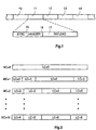
- Fig. 1 shows a section of a time division multiplex data stream which is sent via one communication channel.
- Reference numbers 10 to 14 refer to succeeding data packets. The structure of these data packets is for every data packet identical. For data packet 11, the structure is shown with more details.
- Reference number 15 refers to a first data field which is suited to carry the synchronisation information SYNC for the data packet.
- the second data field 16 carries the HEADER information of the data packet.
- the third data field 17 carries the PAYLOAD of the data packet.
- FIG. 2 different kinds of partitionings of data field 17 of a data packet are shown.
- the multiplex code can have the values 0 to 15.
- a logical channel will carry all data for a certain data source. Examples for this are video data from a video source, audio data for different audio channels, teletext data, control data, telephone data, telefax data, electronic-mail data, etc..
- a multiplex code MC is included in the header of each data packet.
- This multiplex code signals to the receiving end which kind of partitioning is used for this data packet. All used partitionings have to be predefined with previous configuration messages, so that the receiving station of a data packet is capable of analysing the payload of the respective data field.
- a so-called multiplex table is set in each receiving station for this purpose.
- the multiplex table has an entry for each possible partitioning of the data field of a data packet. Therefore, there are 16 different table entries in our above-mentioned example. For defining a multiplex table entry a so-called MultiplexEntrySent-message is used.
- Fig. 7 shows a simplified structure of such a MultiplexEntrySent-message.
- Reference number 70 shows a data field for a start flag STRT. This start flag will be in the bit stream a sequence of bits which have an unmistakable sequence. Bit-stuffing can be used for this purpose.
- Reference number 71 refers to a data field which carries an information item that identifies the configuration message MultiplexEntrySent. This information item is abbreviated with MES. After data field 71 an optional data field 72 follows. Data field 72 carries a so-called sequence number SN. The sequence number is used to differentiate the different configuration messages in case where several configuration messages are sent one after another. The next data field 73 carries the multiplex code MC. In the fifth data field 74, a logical channel number LC is inserted.
- Data field 75 follows and carries the number of bytes which are assigned to the logical channel which is referred to in data field 74.
- the data fields 76 and 77 are optional. Here, more logical channels numbers LC and respective Byte numbers BN can be inserted.
- the MultiplexEntrySent-message ends with a data field for a closing flag END.
- the closing flag can also be an unmistakable sequence of bits in the bit stream.
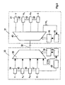
- Reference number 30 stands for a transmitting station and reference number 31 stands for a receiving station. Both stations which communicate with each other via a communication channel 32.
- the example is, therefore, a Point-to-Point-communication.
- Reference number 33 marks a multiplexing device.
- the inputs of the multiplexing device 33 are connected to respective buffer memories 34 to 37.
- Buffer memory 34 stores all data coming from a video source like a video recorder which is not shown in detail.
- Buffer memory 35 stores all data coming from an audio source like the left audio channel of a stereo signal also coming from a video recording device (not shown).
- Buffer memory 36 stores all data of a second audio source like the right channel of a stereo signal coming also from the video recording device (not shown).
- Buffer memory 37 is provided for storing of all teletext data coming from a teletext decoding device which is also not shown but may be included in the video recording device.
- Reference number 49 refers to a analysing unit for the connected buffer memories 34 to 37. Analysing unit 49 calculates the data transport capacity needs for each logical channel which is connected to the multiplexing device 33. Due to different behaviours of data sources, these data transport capacity needs may vary from time to time. When the analysing unit 49 detects that one or more of the buffers 34 to 37 are filled-up more rapidly or more slowly than the time period before, it gives respective data to control unit 38.
- Control unit 38 generates a configuration message which redefines the partitioning of the data field of one or more data packets. This process will be explained more in detail with respect to Fig. 8.
- the configuration message will be,fed to the multiplexing device 33 via the data line CTRL.
- a programming device 39 is provided in the transmitting station. This programming device 39 is responsible for controlling the multiplexing device 33 as defined by control unit 38 which is connected to programming device 39. Therefore, the programming device 39 holds the actual mulitplex table for controlling the multiplexing device 33 for partitioning purposes.
- Reference number 40 refers to a demultiplexing device in the receiving station 31.
- the communication channel 32 is connected.
- the outputs of the demultiplexing device 40 are connected to respective buffer memories 41 to 44.
- a second control unit 45 and a second programming device 46 are also provided.
- Control unit 45 is adapted to analyse all incoming configuration messages via the respective CTRL output of the demultiplexing device 44.
- the actual multiplex table is stored in programming device 46. It is actualized by means of newly received configuration messages as already mentioned before. This actualisation takes place via the connection between control unit 45 and programming device 46.
- Buffer memories 41 to 44 are provided for storing all data of the respective logical channel which transports the video data, the audio data for the left channel of a stereo signal, and for the right audio channel of a respective stereo signal, and all videotext data.
- logical channels are needed to transport all data from the four data sources and the additional control data.
- a new partitioning must be defined via a certain configuration message.
- Fig. 8 There a so-called MultiplexFixedSlotSend-message is shown in a simplified way. All data fields of this message having the same reference number as shown in Fig. 7, define similar data fields and will not be describes once more.
- configuration-message-identification-field 80 a so-called MultiplexFixedSlotSend-code MFSS is inserted.
- data field 81 a numeric label NL is inserted which carries the number of the fixed time slot. If this number is identical to 1, this means, that the first fixed time slot is defined in this message.
- FIG. 5 A second example for defining fixed time slots is given in Fig. 5.
- the configuration message for defining the fixed time slot 50 has also the structure of the message shown in Fig. 8.
- changing a fixed time slot corresponds to sending a new MultiplexFixedSlotSend-message for an already assigned MultiplexFixedSlotNumber NL.
- Fig. 9 a simplified example of a MultiplexFixedSlotSend-message is given that signals that a defined fixed time slot should be deleted. It is apparent from this Fig. that this message does not contain a data field 74 and 75 for an assigned logical channel. This is the command for deleting the fixed time slot.
- Fig. 6 Another example of defining fixed time slots is given in Fig. 6.
- a message identification information item NMEA is inserted in the new data field 82 .
- This information item NMEA defines, that a fixed time slot is to be created for only a single data packet type. Which data packet type should be used is given in data field 73. Therein the multiplex code MC is located, which defines which data packet type is meant. Most of the other data fields are already shown in Fig. 7, so that no further explanation for these data fields is necessary.
- a new data field 83 is included in this NewMultiplexEntrySend-message. This field carries a number NOFS which gives the amount of multiplex elements in the data packet, which are fixed by this message. The assignment of more than one logical channel to a fixed time slot is here not provided.
- All examples of configuration messages given in Fig. 7 to 10 are examples and may be subject of modification. Appropriate acknowledged messages can be defined for each type of the given configuration messages. A new definition of a multiplex table MP will then be valid only after acknowledgment from the receiving station. Furthermore, it is pointed out, that the transmitting station can be modified in such a manner that it also can act as a receiving station and the other way round. This would be necessary for example for videophone applications.
- toggle-flag TOG For error detection purposes in configuration messages and also for the purpose of declaring a new multiplex table entry as valid a toggle-flag TOG is used.
- This toggle-flag is additionally put in each multiplex packet header. It shall change its state each time when a changed multiplex table entry definition is first used or if a fixed time slot is added, modified or deleted.
- the structure of a data packet including a toggle-flag is shown in Fig. 11.
- the toggle-flag is included in the data field for the header of the data packet.
- the data field for the toggle-flag is marked with reference number 19.
- Data field 18 is used for carrying the multiplex code MC. A way to recover a lost configuration message or to randomly access into an ongoing transmission is to periodically re-transmit all configuration messages.
Landscapes
- Engineering & Computer Science (AREA)
- Computer Networks & Wireless Communication (AREA)
- Signal Processing (AREA)
- Time-Division Multiplex Systems (AREA)
- Data Exchanges In Wide-Area Networks (AREA)
Claims (10)
- Verfahren zur Übertragung von Daten unter Verwendung von Zeit-Multiplex, bei dem die Daten in Datenpaketen (10 bis 14) angeordnet sind, wobei die Datenpakete Datenfelder (17) haben, die in Zeitschlitze unterteilt sind, die verschiedenen logischen Kanälen (LC=0 bis LC=6) zugeordnet sind, wobei eine erste Konfigurations-Nachricht erzeugt wird, die eine dynamische Unterteilung der Datenfelder (17) spezifiziert, die an die Bandbreiten-Erfordernisse der Daten angepasst ist, die in die verschiedenen logischen Kanäle eingegeben werden sollen, dadurch gekennzeichnet, dass eine zweite Konfigurations-Nachricht erzeugt wird, die einen Zeitschlitz (47, 48, 50, 60) einem logischen Kanal (LC=0 bis LC=3) auf einer permanenten Basis unabhängig von der dynamischen Unterteilung der Datenfelder (17) gemäß der ersten Konfigurations-Nachricht zuordnet.
- Verfahren nach Anspruch 1, bei dem die permanente Zuordnung des Zeitschlitzes (47, 48, 50, 60) zu dem logischen Kanal (LC=0 bis LC=3) gültig ist, bis eine neue zweite Konfigurations-Nachricht gesendet worden ist, die die Zuordnung modifiziert oder löscht.
- Verfahren nach Anspruch 1 oder 2, bei dem der permanent zugeordnete Zeitschlitz (47, 48, 50, 60) am Beginn des Datenfeldes (17) positioniert wird.
- Verfahren nach einem der Ansprüche 1 bis 3, bei dem ein numerisches Label (81) dem permanent zugeordneten Zeitschlitz (47, 48, 50, 60) zugeordnet wird, wobei das numerische Label (81) die Position des zugeordneten Zeitschlitzes in dem Datenfeld (17) anzeigt.
- Verfahren nach Anspruch 4, bei dem der permanent zugeordnete Zeitschlitz (47, 48, 50 60) durch Senden einer zweiten Konfigurations-Nachricht gelöscht wird, die nur das numerische Label (81) trägt, das dem permanent zugeordneten Zeitschlitz (47, 48, 50, 60) zugeordnet ist, aber keine weiteren Daten.
- Verfahren nach Anspruch 5, bei dem das numerische Label (81) eines gelöschten permanent zugeordneten Zeitschlitzes (47, 48, 50, 60) unbenutzt bleibt, bis in einer weiteren zweiten Konfigurations-Nachricht ein permanent zugeordneter Zeitschlitz (47, 48, 50, 60) mit diesem numerischen Label (81) wieder geöffnet wird.
- Verfahren nach einem der Ansprüche 1 bis 6, bei dem ein Umschalt-Kennzeichen-Feld (19) in dem Header eines Datenpakets (10 bis 14) eingefügt wird und jedes Mal, wenn eine zweite Konfigurations-Nachricht gesendet wird, der Zustand des Umschalt-Kennzeichens (19) in dem Datenpaket (10 bis 14) geändert wird, wo die neue Konfiguration zuerst verwendet wird.
- Verfahren zum Empfangen von Daten unter Verwendung von Zeit-Multiplex, bei dem die Daten in Paketen (10 bis 14) angeordnet sind, wobei die Datenpakete Datenfelder (17) haben, die in Zeitschlitze unterteilt sind, die verschiedenen logischen Kanälen (LC=0 bis LC=6) zugeordnet sind, wobei eine erste Konfigurations-Nachricht analysiert wird, die eine dynamische Unterteilung der Datenfelder (17) spezifiziert, die an die Bandbreiten-Erfordernisse der Daten angepasst ist, die in die verschiedenen logischen Kanäle eingegeben werden sollen, dadurch gekennzeichnet, dass eine zweite Konfigurations-Nachricht analysiert wird, die einen Zeitschlitz (47, 48, 50, 60) einem logischen Kanal (LC=0 bis LC=3) auf einer permanenten Basis unabhängig von der dynamischen Unterteilung der Datenfelder (17) gemäß der ersten Konfigurations-Nachricht zuordnet.
- Sender zum Übertragen von Daten unter Verwendung von Zeit-Multiplex, umfassend:Multiplex-Mittel (33) zum Zeit-Multiplexen von Datenpaketen (10 bis 14) ;Mittel (39) zum Unterteilen von Datenfeldern (17) der Datenpakete (10 bis 14) in Zeitschlitze und zum Zuordnen verschiedener logischer Kanäle (LC=0 bis LC=6) zu den Zeitschlitzen;Einen Konfigurations-Nachrichten-Generator (38) zum Erzeugen von ersten und zweiten Konfigurations-Nachrichten, wobei die erste Konfigurations-Nachricht eine dynamische Unterteilung der Datenfelder (17) spezifiziert, die an die Bandbreiten-Erfordernisse der Daten angepasst sind, die in die verschiedenen logischen Kanäle eingegeben werden sollen, und wobei die zweite Konfigurations-Nachricht einen Zeitschlitz (47, 48, 50, 60) einem logischen Kanal (LC=0 bis LC=3) auf einer pernamenten Basis unabhängig von der dynamischen Unterteilung der Datenfelder (17) gemäß der ersten Konfigurations-Nachricht zuordnet.
- Empfänger zum Empfang von Zeit-Multiplex-Daten umfassend:einen Konfigurations-Nachrichten-Analysierer (45) zum Analysieren einer ersten und einer zweiten Konfigurations-Nachricht, wobei die erste Konfigurations-Nachricht die dynamische Unterteilung von Datenfeldern (17) von empfangenen Datenpaketen (10 bis 14) spezifiziert, die an die Bandbreiten-Erfordernisse der Daten angepasst sind, die in verschiedene logische Kanäle eingegeben werden sollen, und wobei die zweite Konfigurations-Nachricht einen Zeitschlitz (47, 48, 50, 60) einem logischen Kanal (LC=0 bis LC=3) auf einer permanenten Basis unabhängig von der dynamischen Unterteilung der Datenfelder (17) gemäß der ersten Konfigurations-Nachricht zuordnet;Mittel (46) zum Steuern von Demultiplex-Mitteln (40) auf der Basis der analysierten ersten und zweiten Konfigurations-Nachricht;Demultiplex-Mittel (40) zum Zeit-Demultiplexen der logischen Kanäle (LC=0 bis LC=6), die den Zeitschlitzen in den Datenfeldern (17) der empfangenen Datenpakete zugeordnet sind.
Priority Applications (2)
| Application Number | Priority Date | Filing Date | Title |
|---|---|---|---|
| DE69628650T DE69628650T2 (de) | 1996-09-27 | 1996-09-27 | Übertragungsverfahren zwischen zwei oder mehr Stationen über einen Kommunikationskanal und Sende- und Empfangsstation zur Verwendung des Verfahrens |
| EP19960115569 EP0833471B1 (de) | 1996-09-27 | 1996-09-27 | Übertragungsverfahren zwischen zwei oder mehr Stationen über einen Kommunikationskanal und Sende- und Empfangsstation zur Verwendung des Verfahrens |
Applications Claiming Priority (1)
| Application Number | Priority Date | Filing Date | Title |
|---|---|---|---|
| EP19960115569 EP0833471B1 (de) | 1996-09-27 | 1996-09-27 | Übertragungsverfahren zwischen zwei oder mehr Stationen über einen Kommunikationskanal und Sende- und Empfangsstation zur Verwendung des Verfahrens |
Publications (2)
| Publication Number | Publication Date |
|---|---|
| EP0833471A1 EP0833471A1 (de) | 1998-04-01 |
| EP0833471B1 true EP0833471B1 (de) | 2003-06-11 |
Family
ID=8223230
Family Applications (1)
| Application Number | Title | Priority Date | Filing Date |
|---|---|---|---|
| EP19960115569 Expired - Lifetime EP0833471B1 (de) | 1996-09-27 | 1996-09-27 | Übertragungsverfahren zwischen zwei oder mehr Stationen über einen Kommunikationskanal und Sende- und Empfangsstation zur Verwendung des Verfahrens |
Country Status (2)
| Country | Link |
|---|---|
| EP (1) | EP0833471B1 (de) |
| DE (1) | DE69628650T2 (de) |
Families Citing this family (6)
| Publication number | Priority date | Publication date | Assignee | Title |
|---|---|---|---|---|
| JP3938824B2 (ja) * | 1999-10-29 | 2007-06-27 | 松下電器産業株式会社 | 通信装置および通信方法 |
| WO2001078279A1 (en) * | 2000-04-10 | 2001-10-18 | Appian Communications, Inc. | Network interface |
| KR100677378B1 (ko) | 2004-11-02 | 2007-02-02 | 엘지전자 주식회사 | Wcdma 단말기의 영상 통화 데이터 인코딩 방법 |
| JP4596135B2 (ja) * | 2005-01-11 | 2010-12-08 | 日本電気株式会社 | 多重化装置およびそのデータ処理方法 |
| US7835383B2 (en) | 2005-09-30 | 2010-11-16 | Robert Bosch Gmbh | Method and system for providing a modified timed division multiple access (TDMA) for reduced delay |
| CN107566074B (zh) | 2016-06-30 | 2019-06-11 | 华为技术有限公司 | 光传送网中传送客户信号的方法及传送设备 |
Family Cites Families (3)
| Publication number | Priority date | Publication date | Assignee | Title |
|---|---|---|---|---|
| AU627953B2 (en) * | 1989-11-15 | 1992-09-03 | Digital Equipment Corporation | Integrated communications link having dynamically allocatable bandwidth and a protocol for transmission or allocation information over the link |
| FR2670969B1 (fr) * | 1990-12-19 | 1993-04-16 | France Etat | Systeme de transmission de donnees par repartition dans l'espace temps-frequence, avec structuration en canaux. |
| US5229992A (en) * | 1991-03-28 | 1993-07-20 | Sprint International Communications Corp. | Fixed interval composite framing in integrated services networks |
-
1996
- 1996-09-27 EP EP19960115569 patent/EP0833471B1/de not_active Expired - Lifetime
- 1996-09-27 DE DE69628650T patent/DE69628650T2/de not_active Expired - Lifetime
Also Published As
| Publication number | Publication date |
|---|---|
| DE69628650T2 (de) | 2004-02-05 |
| EP0833471A1 (de) | 1998-04-01 |
| DE69628650D1 (de) | 2003-07-17 |
Similar Documents
| Publication | Publication Date | Title |
|---|---|---|
| EP0740431B1 (de) | Verfahren zur TDMA Verwaltung, Zentralstation, Teilnehmerstation und Netzwerk zur Ausführung des Verfahrens | |
| EP0119105B1 (de) | Integriertes Leitung/Paket Vermittlungssystem | |
| US5005171A (en) | Telecommunication transmission format suited for network-independent timing environments | |
| US4700341A (en) | Stochastic time division multiplexing | |
| US5537393A (en) | BLSR network having path-AIS generation function | |
| EP0617866B1 (de) | Vorrichtung und verfahren zur formatierung von datenpaketen variabler länge für ein übertragungsnetz | |
| EP0444207B1 (de) | Vielfachzugriffssystem für ein übertragungsnetz | |
| JPH09507991A (ja) | 情報通信方法および端末 | |
| US6188697B1 (en) | ATM cell transport system for wireless communications | |
| US6414967B2 (en) | Transmission system with flexible frame structure | |
| US10841674B2 (en) | Timeslot management method, a related network terminator, a related line terminator and an upstream signal frame structure for a time division multiple access system | |
| EP0833471B1 (de) | Übertragungsverfahren zwischen zwei oder mehr Stationen über einen Kommunikationskanal und Sende- und Empfangsstation zur Verwendung des Verfahrens | |
| KR100480186B1 (ko) | 전송시스템,전송방법,수신방법,전송기및수신기 | |
| US5430710A (en) | Order preserving transmission of data streams | |
| US6504840B1 (en) | Method, system and apparatus for transferring information between nodes in a circuit switched time division multiplexed method | |
| KR20010102399A (ko) | 데이터 통신 | |
| EP0522611B1 (de) | Verfahren zur paketierung kontinuierlicher daten und paketdaten in rahmen | |
| CA2064581C (en) | Data transmission on optical networks | |
| US5475706A (en) | Bulk data transmission system | |
| US4477899A (en) | Digital data transmission system with time division/packet transformation function | |
| US20020141411A1 (en) | Apparatus for line-concentrating and distributing PPP frame data | |
| JPH0544212B2 (de) | ||
| US7190697B2 (en) | Multiplexing of selection from among streams and parsed-out time synchronization information | |
| US20080273530A1 (en) | Transmission of digital information in a frame switched data network | |
| EP0698322B1 (de) | Verfahren zur steuerung bedingter verbindungen in einem fernmeldesystem |
Legal Events
| Date | Code | Title | Description |
|---|---|---|---|
| PUAI | Public reference made under article 153(3) epc to a published international application that has entered the european phase |
Free format text: ORIGINAL CODE: 0009012 |
|
| AK | Designated contracting states |
Kind code of ref document: A1 Designated state(s): DE FR GB IT |
|
| 17P | Request for examination filed |
Effective date: 19980924 |
|
| AKX | Designation fees paid |
Free format text: DE FR GB IT |
|
| RBV | Designated contracting states (corrected) |
Designated state(s): DE FR GB IT |
|
| 17Q | First examination report despatched |
Effective date: 20011203 |
|
| GRAH | Despatch of communication of intention to grant a patent |
Free format text: ORIGINAL CODE: EPIDOS IGRA |
|
| GRAH | Despatch of communication of intention to grant a patent |
Free format text: ORIGINAL CODE: EPIDOS IGRA |
|
| GRAA | (expected) grant |
Free format text: ORIGINAL CODE: 0009210 |
|
| AK | Designated contracting states |
Designated state(s): DE FR GB IT |
|
| REG | Reference to a national code |
Ref country code: GB Ref legal event code: FG4D |
|
| REG | Reference to a national code |
Ref country code: GB Ref legal event code: 746 Effective date: 20030624 |
|
| REF | Corresponds to: |
Ref document number: 69628650 Country of ref document: DE Date of ref document: 20030717 Kind code of ref document: P |
|
| ET | Fr: translation filed | ||
| PLBE | No opposition filed within time limit |
Free format text: ORIGINAL CODE: 0009261 |
|
| STAA | Information on the status of an ep patent application or granted ep patent |
Free format text: STATUS: NO OPPOSITION FILED WITHIN TIME LIMIT |
|
| REG | Reference to a national code |
Ref country code: FR Ref legal event code: D6 |
|
| 26N | No opposition filed |
Effective date: 20040312 |
|
| PGFP | Annual fee paid to national office [announced via postgrant information from national office to epo] |
Ref country code: DE Payment date: 20130924 Year of fee payment: 18 |
|
| PGFP | Annual fee paid to national office [announced via postgrant information from national office to epo] |
Ref country code: GB Payment date: 20130926 Year of fee payment: 18 Ref country code: FR Payment date: 20130918 Year of fee payment: 18 |
|
| PGFP | Annual fee paid to national office [announced via postgrant information from national office to epo] |
Ref country code: IT Payment date: 20130916 Year of fee payment: 18 |
|
| REG | Reference to a national code |
Ref country code: DE Ref legal event code: R119 Ref document number: 69628650 Country of ref document: DE |
|
| GBPC | Gb: european patent ceased through non-payment of renewal fee |
Effective date: 20140927 |
|
| REG | Reference to a national code |
Ref country code: FR Ref legal event code: ST Effective date: 20150529 |
|
| PG25 | Lapsed in a contracting state [announced via postgrant information from national office to epo] |
Ref country code: DE Free format text: LAPSE BECAUSE OF NON-PAYMENT OF DUE FEES Effective date: 20150401 Ref country code: GB Free format text: LAPSE BECAUSE OF NON-PAYMENT OF DUE FEES Effective date: 20140927 |
|
| PG25 | Lapsed in a contracting state [announced via postgrant information from national office to epo] |
Ref country code: IT Free format text: LAPSE BECAUSE OF NON-PAYMENT OF DUE FEES Effective date: 20140927 Ref country code: FR Free format text: LAPSE BECAUSE OF NON-PAYMENT OF DUE FEES Effective date: 20140930 |