EP0833542A2 - Lokales Netzwerk mit Sende- und Empfangsvorrichtung - Google Patents
Lokales Netzwerk mit Sende- und Empfangsvorrichtung Download PDFInfo
- Publication number
- EP0833542A2 EP0833542A2 EP97202892A EP97202892A EP0833542A2 EP 0833542 A2 EP0833542 A2 EP 0833542A2 EP 97202892 A EP97202892 A EP 97202892A EP 97202892 A EP97202892 A EP 97202892A EP 0833542 A2 EP0833542 A2 EP 0833542A2
- Authority
- EP
- European Patent Office
- Prior art keywords
- buffer memory
- cells
- cell
- terminal
- transmitting
- Prior art date
- Legal status (The legal status is an assumption and is not a legal conclusion. Google has not performed a legal analysis and makes no representation as to the accuracy of the status listed.)
- Granted
Links
- 230000015654 memory Effects 0.000 claims abstract description 99
- 239000000872 buffer Substances 0.000 claims abstract description 97
- 230000005540 biological transmission Effects 0.000 claims abstract description 55
- 238000012790 confirmation Methods 0.000 claims abstract description 10
- 230000008878 coupling Effects 0.000 claims description 18
- 238000010168 coupling process Methods 0.000 claims description 18
- 238000005859 coupling reaction Methods 0.000 claims description 18
- 230000003139 buffering effect Effects 0.000 claims description 16
- 238000012546 transfer Methods 0.000 claims description 14
- 238000004364 calculation method Methods 0.000 claims description 5
- 238000000034 method Methods 0.000 description 23
- 238000011156 evaluation Methods 0.000 description 17
- 230000006870 function Effects 0.000 description 16
- 239000011159 matrix material Substances 0.000 description 16
- 230000011664 signaling Effects 0.000 description 10
- 238000005457 optimization Methods 0.000 description 2
- 238000012545 processing Methods 0.000 description 2
- 230000006978 adaptation Effects 0.000 description 1
- 230000015572 biosynthetic process Effects 0.000 description 1
- 230000000903 blocking effect Effects 0.000 description 1
- 238000004891 communication Methods 0.000 description 1
- 238000010276 construction Methods 0.000 description 1
- 230000001419 dependent effect Effects 0.000 description 1
- 238000010586 diagram Methods 0.000 description 1
- 230000002093 peripheral effect Effects 0.000 description 1
- 230000001960 triggered effect Effects 0.000 description 1
- 238000002604 ultrasonography Methods 0.000 description 1
- 208000037820 vascular cognitive impairment Diseases 0.000 description 1
Images


Classifications
-
- H—ELECTRICITY
- H04—ELECTRIC COMMUNICATION TECHNIQUE
- H04L—TRANSMISSION OF DIGITAL INFORMATION, e.g. TELEGRAPHIC COMMUNICATION
- H04L12/00—Data switching networks
- H04L12/28—Data switching networks characterised by path configuration, e.g. LAN [Local Area Networks] or WAN [Wide Area Networks]
-
- H—ELECTRICITY
- H04—ELECTRIC COMMUNICATION TECHNIQUE
- H04Q—SELECTING
- H04Q11/00—Selecting arrangements for multiplex systems
- H04Q11/04—Selecting arrangements for multiplex systems for time-division multiplexing
- H04Q11/0428—Integrated services digital network, i.e. systems for transmission of different types of digitised signals, e.g. speech, data, telecentral, television signals
- H04Q11/0478—Provisions for broadband connections
-
- H—ELECTRICITY
- H04—ELECTRIC COMMUNICATION TECHNIQUE
- H04L—TRANSMISSION OF DIGITAL INFORMATION, e.g. TELEGRAPHIC COMMUNICATION
- H04L12/00—Data switching networks
- H04L12/54—Store-and-forward switching systems
- H04L12/56—Packet switching systems
- H04L12/5601—Transfer mode dependent, e.g. ATM
- H04L2012/5603—Access techniques
- H04L2012/5604—Medium of transmission, e.g. fibre, cable, radio
- H04L2012/5607—Radio
-
- H—ELECTRICITY
- H04—ELECTRIC COMMUNICATION TECHNIQUE
- H04L—TRANSMISSION OF DIGITAL INFORMATION, e.g. TELEGRAPHIC COMMUNICATION
- H04L12/00—Data switching networks
- H04L12/54—Store-and-forward switching systems
- H04L12/56—Packet switching systems
- H04L12/5601—Transfer mode dependent, e.g. ATM
- H04L2012/5603—Access techniques
- H04L2012/5609—Topology
- H04L2012/5612—Ring
-
- H—ELECTRICITY
- H04—ELECTRIC COMMUNICATION TECHNIQUE
- H04L—TRANSMISSION OF DIGITAL INFORMATION, e.g. TELEGRAPHIC COMMUNICATION
- H04L12/00—Data switching networks
- H04L12/54—Store-and-forward switching systems
- H04L12/56—Packet switching systems
- H04L12/5601—Transfer mode dependent, e.g. ATM
- H04L2012/5614—User Network Interface
- H04L2012/5615—Network termination, e.g. NT1, NT2, PBX
Definitions
- the invention relates to a local, after the asynchronous transfer mode working network with a first transmitting and receiving device, the one Radio device for transmitting cells to several other transmitters and Contains receivers.
- a local area network (LAN) that uses the asynchronous transfer mode works is known from EP 0 660 567 A2.
- This network contains Network interfaces with a radio device for the transmission of cells between the individual network interfaces.
- the cells are transferred according to a ring principle.
- a network interface always transmits cells the ring, i.e. always to a neighboring network interface. Possibly the cells must reach their destination via several other network interfaces are given.
- a circuit element is provided which Assigns time slots to network interfaces.
- the invention has for its object to provide a local network which enables a different service request in the radio device becomes.
- the transmitting and receiving device can each be a terminal, which is a station and a network interface form (adhoc wireless ATM-LAN).
- the station can be, for example Videophone, a personal computer, a workstation or a remote speaker be.
- a network interface contains at least one for establishing a connection provided control arrangement and a coupling device for switching Cells between radio device, station and control arrangement.
- the terminals exchange their data directly with another terminal.
- the first transmitting and receiving device is a network interface coupled with several other network interfaces connected in a ring is (basestation oriented wireless ATM-LAN).
- a network interface a control arrangement provided at least for establishing a connection and a Coupling device for switching cells between ring connections, Radio device and control arrangement.
- the other sending and receiving devices each form a terminal, which is used to exchange data with a Network interface is provided.
- the latter terminals do not contain any Network interface.
- a first buffer memory stores all of an assigned one Network interface cells coming to the sending and receiving device to be transmitted, the relevant first buffer memory assigned.
- Sending and receiving devices are prevented from blocking repeated cell transmission occurs when a particular transmit and Receiving device cannot receive cells because e.g. is broken.
- Continue can adapt to different transmission speeds between the first and other transmitting and receiving devices by different Readout speeds from the first buffer memories can be set. Herewith among other things accomplishes different service requests using different Buffer memory can be realized in the radio device.
- Radio transmission means that data is transmitted over the wire (e.g. Radio transmission, infrared transmission, ultrasound transmission).
- the radio device contains a first control circuit which is used to delete a Cell in a first buffer memory after confirmation of proper Receiving an associated receiving device is provided.
- a sorting process can also be carried out with the first control circuit.
- first control circuit for sorting the cells in the relevant first Buffer storage provided after the remaining lifetime.
- the first control circuit calculates the remaining lifespan of a cell by subtracting the time of the cell Calculation and addition of the storage time from the specified maximum Dwell time and gives out the cell with the least remaining lifespan first buffer memory for reading free.
- the control circuit does not sort those cells in which after reading from a first buffer memory no confirmation of receipt has been received within a buffering period or the waiting time for a confirmation has not yet expired.
- the Buffering time indicates the time in which a cell is still for the reading process can be used and depends on the respective application. At a Voice transmission, the buffering time is usually zero.
- the cells read from the first buffer memories are merged and buffered in a second buffer memory.
- a second control circuit leads also a sorting process of the cells buffered in the second buffer memory remaining lifetime through.
- the second control circuit is for counting the number of transmitters and receivers cells to be sent and forwarded to a control device intended.
- the control device can only be made up of terminals with one Network interface existing local network can be a selected terminal. In the case of the network interfaces connected via a ring, devices form the control device of the respective network interfaces.
- the control device is used to assign the number of cells that are Transmitting and receiving device to another transmitting and receiving device are to be transferred.
- the invention further relates to a radio device of a first transmitting and Receiving device in a local, after the asynchronous transfer mode working network for the transmission of cells to several transmitters and Receiving devices.
- the radio device each contains a different transceiver assigned first buffer memory.
- a first buffer memory is intended for storing a cell, the destination of which is another transmit and Receiving device, which is the relevant first buffer memory assigned.
- the local network can also have one or contain several more rings. When using two rings, the Flow of information about the rings can be in opposite directions.
- a network interface 1 through 8 and one Terminals 9 to 21 each contain a radio device for transferring information or messages via the radio transmission paths.
- the network interface 1 is the terminals 9, 10 and 11, the network interface 2, the terminals 12 and 13, the network interface 3 the terminal 14, the network interface 4 the terminal 15, the network interface 5 the terminals 16 and 17, the network interface 6 the terminal 18, the Network interface 7, the terminals 19 and 20 and the network interface 8 that Assigned to Terminal 21.
- a terminal 9 to 21 contains, for example, one Videophone, a personal computer, a workstation or one Telephone.
- the ring there are messages or information between the network interfaces 1 to 8 using the asynchronous transfer mode (ATM) transferred from cells.
- ATM asynchronous transfer mode
- One or more cells are included for the Radio control necessary additional control and additional information (overhead) Mistake.
- a cell contains a header field with 5 bytes, for example, and an information field with for example 48 bytes.
- the information contained in the header of the cell are used in particular for addressing and for performing switching functions.
- the network interface 1 is also coupled to a database 22, via which For example, data can be taken for a connection establishment, the via the resources of the respective terminals 9 to 21 or via the network topology Can provide information.
- the network interface 1 is additional still for the administration of data and for the control of the connection establishment and dismantling provided.
- the network interfaces (1 to 8) and the assigned terminals (9 to 21) can each be different Carrier frequencies can be assigned.
- the assignment of a time slot for one Connection is e.g. while connecting from the network interface 1 and / or per time period (frame) depending on the Requirements of the terminals concerned. It is also possible only that Apply TDMA procedure for the entire local network. Here is each a period (subframe) of a superframe of a network interface assigned.
- a network interface 1 to 8 of FIG. 1, each part of two opposite rings and is indicated below with the reference numeral 23 is shown in more detail in FIG.
- the network interface 23 contains a coupling device 24, the buffer memory 25 to 28 with ring connections 29 to 32 and one Radio device 33 is coupled and mediates the cell current.
- the Funkvor direction 33 is via the connections 38 and 39 with the coupling device 24 coupled.
- the buffer memory 25 is on the one hand with the receiving ring connection 29 of the first Rings and on the other hand with a connection 34, which leads to the coupling device 24, coupled.
- the buffer memory 25 also receives a first receive clock signal, which is derived from the cell current of the reception ring connection 29, and a internal clock signal from a clock generator of the network interface 23.
- the buffer memory 26 is coupled to the coupling device 24 via a connection 35 and supplies a cell current to the transmit ring terminal 30 of the first ring.
- the Buffer memory 26 provides the internal clock signal and a first transmit clock signal which is derived, for example, from the internal clock signal.
- the buffer memory 27 receives a cell current from the reception ring terminal 31 a second ring and supplies a cell current via a connection 36 to Coupling device 24. Receives from a connection 37 of the coupling device 24 the buffer memory 28 cells connected to the transmit ring port 32 of the second ring to get redirected.
- the buffer memory 27 receives a second receive clock signal, which is derived from the cell current of the reception ring connection 31, and the internal clock signal.
- the buffer clock 28 becomes the internal clock signal and second transmit clock signal supplied, which for example from the internal clock signal is derived.
- buffer memories 25 to 28 there is an adaptation of the cell current a clock signal instead. Deriving the various clock signals from the cell stream and the generation of the internal clock signal in the clock generator are not here shown in more detail.
- control arrangement 40 included, for example for establishing a connection and dismantling serves.
- the control arrangement 40 which can be implemented as a microprocessor can, maintains and also generates cells.
- Switching matrix 41 three path storage arrangements 42, 43 and 44 and three receiving circuits 45, 46 and 47 included.
- receiving circuits 45, 46 and 47 are the header fields of incoming via connections 29, 31 and 39 Cells evaluated.
- Address information contained in the header field is used for control various tables for those with the receiving circuits 45, 46 and 47 connected path storage arrangements 42, 43 and 44 used.
- the in the Tabled data are received by the receiving circuits 45, 46 and 47 used to organize the further processing and forwarding of the cell.
- the receiving circuit 45 can copy the cell and with provide new address information.
- the original cell is e.g. B. about that Switching matrix 41 to radio device 33 and the copied cell via the switching matrix 41 given to the buffer memory 26. There is still a possibility that the Switching matrix 41 performs functions such as this copying function.
- the receiving circuit 45 is connected to the buffer memory 25 via the connection 34 coupled and forwards received cells to switching matrix 41.
- the path storage arrangement 42 is connected to the receiving circuit 45.
- the Receive circuit 46 which is connected to the path storage arrangement 43, receives Cells from the buffer memory 27 and forwards cells to the switching matrix 41.
- the receiving circuit 47 is between the switching matrix 41 and the connection 39 arranged, which is connected to the path storage arrangement 44.
- VCI virtual channel identifier
- VPI virtual path identifier
- the VPI and the VCI together denote one virtual connection between at least two users by a number and are defined during the connection establishment. Under one user is e.g. a user of a program in a terminal, another program, stored data (terminal as database) or even a telephone subscriber understand.
- the VPI also specifies a bundle of virtual connections. When establishing a connection, certain attributes, which are defined by VPI and VCI marked connections are assigned in the tables of the routing storage arrangements 42 to 44 saved. An attribute indicates, for example, the type of connection a virtual connection.
- a connection type is a single connection (unicast connection), one Multiple connection (multicast connection) or a distribution connection (broadcast connection) to understand.
- a single connection or end-to-end connection there is a virtual connection of a user of a first one Terminals with a user of a second terminal.
- a multiple connection or point-to-multipoint connection are multiple users of Terminals connected to a sending terminal.
- a distribution connection delivers a transmission terminal to all other terminals with the same content in the cell Information field.
- a terminal 9 to 21 can, for example, from a personal computer 48 and a radio device 49, as shown in FIG. 3.
- the personal computer 48 exchanges cells with the radio device 49, which for radio transmission with the assigned network interface (1 to 8) is responsible.
- the radio device 33 in the network interface 23 and the radio device 49 in a terminal (9 to 21) contain an antenna 50, a radio frequency circuit 51, a modem 52 and a protocol device 53 (Fig. 4). Except for the Protocol device 53 require the other switching elements 50 to 52 of FIG Radio 33 and 49 no further explanation as this is from others Radio devices are known circuit elements.
- the protocol device 53 forms packet units from the received ATM cell stream, each of which contain and at least one ATM cell and control information here the ones suitable for multiple access in a radio transmission medium and error reducing protocols. These protocols refer to the OSI layer model.
- the data link layer is the OSI layer model relevant. This contains at least two further sub-layers: LLC and MAC layer.
- the MAC layer controls the multiple access of the terminals Transmission medium (radio transmission medium).
- LLC Logical Link Control
- MAC and LLC layer performs flow and error control.
- MAC and LLC layer can further, for example, the book "Computer Networks” by Andrew S. Tanenbaum, Second Edition, Prentice-Hall International, Inc., 1988, Pages 117 to 131, 196 to 212 and 262 to 265. Circuits, which functions of the MAC and LLC layers are described below explained.
- the network interfaces 1 to 8 and the assigned Terminals 9 to 21 each transmit data on a different one Carrier frequency (FDMA).
- FDMA Carrier frequency
- For the transfer of data between one Network interface and an assigned terminal are assigned Time slots used (TDMA).
- a frame contains a collision Channel or time slot (hereinafter referred to as registration channel), several collision-free MAC signaling channels or time slots for each terminal and Transport channels or time slots for useful information. On the registration channel can access any terminal, causing collisions with other terminals can arise.
- a terminal can be accessed via the registration channel Switch on when registering with the assigned network interface.
- a MAC signaling channel is permanently assigned to a terminal and serves the MAC control information between the terminal and the network interface exchange.
- the MAC control information comes from the MAC layer associated protocol and serve e.g. for dynamic reservation of the Transport time slots for the payload.
- the respective terminal shares the network interface with how many cells each in a buffer for Transfer ready.
- the network interface e.g. depending on the Buffer fill level of cells pending for transmission in the entire radio coverage area terminals, the transport channels of the individual terminals to.
- the assignment is usually renewed before each new time frame.
- the assignment for the entire transport channels can also be made dynamically.
- a terminal After commissioning a terminal, it sends it to the assigned network interface (e.g. network interface 5) a registration request with the Terminal-assigned identification number (ID number) via the registration channel.
- the registration request is received in the radio device 33 from the coupling device 24 after querying the path storage arrangement 44 for Control arrangement 40 sent.
- the registration request of the terminal is made with Help from a control cell from the control arrangement 40 of the network interface 5 sent via the ring to network interface 1, which contains the identification number of the terminal in the database 22.
- the reception in the Network interface 1 is connected to the control arrangement 40 Network interface 5 sent control cell acknowledged and then another Acknowledgment message sent back to the terminal. Except for the acknowledgment message the terminal also receives information about the assigned MAC signaling channel communicated.
- the control arrangement 40 of a network interface controls the connection establishment and dismantling between users of terminals. There will be similar ones Control processes, such as those used in the European patent application EP 0 641 105 A2 are described.
- connection between two users of terminals will be described as an example.
- the terminal 18 assigned to the network interface 6 with a user A 1 would like to establish a connection with a user A 2 of the terminal 12 assigned to the network interface 2.
- the control arrangement 40 of the network interface 1 receives Control cells with a connection request and then checks whether there is one Connection is possible (e.g. it is checked whether Terminal 12 is registered). If the Connection is allowed, this virtual connection becomes a logical number assigned. This logical number can be used for the ring and the radio links each have different VPIs and VCIs.
- a network interface (1 to 8) carries out this implementation.
- the network interface 1 divides by means of control cells the control arrangements 40 of the network interfaces 2 and 6 with that a virtual Connection between the terminals 12 and 18 is established.
- the respective Control arrangements 40 of the network interfaces 2 and 6 still have to check whether sufficient for the virtual connection to the respective terminal 12 or 18 Transmission capacity is available over the radio link. It must be for the The radio link has a sufficient transmission capacity for a connection Average are available. However, this can vary from frame to frame vary. Circuit arrangements could be responsible for the dynamic time slot allocation the MAC layer or the control arrangement 40.
- the Network interfaces 2 and 6 share their terminals 12 and 18 via the Radio link the VPI and VCI you have provided for the radio link for connection with. So it can be used for the radio link and the ring different but corresponding VPI and VCI are assigned.
- the network interface 6 routes one sent out by the terminal 18 and forward the received cell to its corresponding transmit ring port.
- the the actual switching process is carried out by the coupling device 24 of the network interface 6, which after evaluation of the table in the path storage arrangement 44 the cell current received by the terminal 18, for example, to the send ring connection 30 of the network interface 6 forwards.
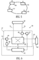
- FIG. 5 shows an exemplary embodiment of a further local network with 4 Terminals 54 to 57 are shown, each exchanging data via radio links.
- the ellipse shown in FIG. 5 and comprising the terminals 54 to 57 is said to be specify the radio range in which between two terminals (54 to 57) problem-free radio transmission is possible.
- the station 58 can, for example, an image telephone, a personal computer, be a workstation or a telephone.
- the network interface 59 contains a control arrangement 61 and a coupling device 62, which via a transmit port 63 and a receive port 64 with the radio 60 is coupled and mediates cells generated according to the asynchronous transfer mode.
- Cells can be generated by either control arrangement 61 or station 58 are received by the radio device 60 via the radio link.
- the control arrangement 61 which can be implemented as a microprocessor, serves, for example for setting up and clearing down virtual connections, e.g. B. between two Users of different terminals.
- the coupling device 62 there is also a switching matrix 65, two path storage arrangements 66 and 67 and two receiving circuits 68 and 69 included.
- the Receive circuit 68 is connected to the receive terminal 64, with an input of the Switching matrix 65 and connected to the path storage arrangement 66.
- An exit of the switching matrix 65 is connected to the transmission connection 63.
- the receiving circuit 69 is arranged, which with the Path storage arrangement 67 is coupled.
- An input port 71 of station 58 is still connected to another output of switching matrix 65.
- the header fields are the over the Receive port 64 and the output port 70 incoming cells evaluated. Address information contained in the header field is used for control various tables for those connected to receiving circuits 68 and 69 Path storage arrangements 66 and 67 are used. The ones stored in the tables Data is used by the receiving circuits 68 and 69, respectively, to transmit the organize further processing and forwarding of the cell. For example receive circuit 69 can copy a cell and add new address information Mistake. The original cell is e.g. over the switching network 65 to the Radio device 60 and the copied cell via switching matrix 65 to station 58 returned. There is still the possibility that the switching matrix 65 such Performs functions like this copy function. The receiving circuit 68 conducts cells received by the radio device 60 to the switching matrix 65.
- the radio device 60 in a terminal 54 to 57 is made of the same circuit elements constructed like the radio devices 33 and 49 and contains antenna 50, Radio frequency circuit 51, modem 52 and protocol device 53 (Fig. 3).
- TDMA Time Division Multiplex Access
- FDMA Frequency Division Multiplex Access
- CDMA Code Division Multiplex access
- the methods can also, if necessary be combined.
- a time slot is a frame after TDMA procedure assigned to a terminal for a specific connection.
- the duration of a time slot could be the duration of one or a multiple of a cell and additional control and necessary for radio transmission Additional information corresponds.
- the assignment of a time slot for one Connection is e.g. before transferring a frame depending on the Requirements of the terminals concerned.
- TDMA Time division multiplex method
- a frame contains like in the local network according to FIG. 1, a collision-prone channel or time slot (hereinafter referred to as registration channel), several collision-free MAC signaling channels or time slots and transport channels or time slots for Useful information. Every terminal can access the registration channel which can cause collisions with other terminals.
- registration channel On the Registration channel leaves a terminal after switching on at the terminal register, which performs the management function for the local network.
- This terminal whose control arrangement 61 is responsible for management, is referred to below as a controller.
- a MAC signaling channel is permanently assigned to a terminal and is used to the MAC control information between the terminal and the controller exchange.
- the MAC control information comes from the MAC layer associated protocol and serve e.g. for dynamic reservation of the Transport time slots for the payload.
- the respective terminal shares the controller with how many cells each in a buffer for transmission stand by.
- the controller e.g. depending on the buffer level of for transmission of pending cells in the entire radio range
- the Allocation is usually renewed before each new time frame. Also the assignment can be done dynamically for the entire transport channels.
- terminal 54 is the controller.
- the controller can be used during a frame e.g. Terminal 55 a first transport time slot or channel for the Transfer of data to Terminal 56, the second transport channel Terminal 56 for the transmission of data to Terminal 55, the third transport channel Terminal 56 again for the transmission of data to Terminal 54 fourth transport channel to terminal 54 for the transmission of data to Terminal 57, the fifth transport channel to Terminal 57 for the transmission of Provide data for Terminal 55 etc.
- the controller can Receive all MAC signaling information an optimization process in order to average each terminal an optimal number of transport channels to provide.
- the controller also serves to establish and clear a connection. Before a connection can be established, a terminal must be connected to the Controller can be registered. Here, a terminal sends after commissioning the controller a registration request with that assigned to the terminal Identification number (ID number) via the registration channel. Of the Registration request is received in the radio device 60 of the controller from the coupling device 62 after querying the path storage arrangement 66 for Control arrangement 61 sent. The controller sets the identification number of the Terminals in e.g. in a database coupled to the control arrangement. Of the Receipt in the controller is via an acknowledgment message sent to the terminal approved. In addition to the acknowledgment message, the terminal also receives the Information about the assigned MAC signaling channel communicated.
- ID number Terminal Identification number
- the controller sets the identification number of the Terminals in e.g. in a database coupled to the control arrangement. Of the Receipt in the controller is via an acknowledgment message sent to the terminal approved. In addition to the acknowledgment message, the terminal also receives the Information about the assigned MAC
- Terminal 55 with user A 3 wants to establish a connection with user A 4 of terminal 57.
- the controller is the terminal 54.
- the MAC signaling is used to implement the exchange of ATM cells (user and control cells) over the direct radio link between two terminals.
- the circuit arrangements of the MAC layer enable the above-mentioned dynamic time slot allocation regardless of the content of the ATM cells.
- the control arrangement 61 of the controller receives control cells with a connection request and then checks whether there is one Connection is possible (e.g. it is checked whether Terminal 57 is registered). If the Connection is allowed, this virtual connection becomes a logical number in Formed by VPI and VCI.
- the controller divides the by means of control cells Control arrangements 61 of the terminals 55 and 57 with that a virtual connection is constructed.
- the control arrangement 61 of the controller has previously checked whether for the virtual connection sufficient transmission capacity over the radio link is available. There must be a connection for the radio link sufficient transmission capacity is available on average. This can however vary from frame to frame during radio transmission.
- Control arrangement 61 of the controller or circuits of the MAC layer responsible for the dynamic time slot allocation during radio transmission is the Control arrangement 61 of the controller or circuits of the MAC layer. While of the connection establishment are also those for a specific transmission section in the network (e.g. radio link) and a circuit section (Connections 70 and 71) in the terminal the intended VPI and VCI for the Connection communicated.
- the network interface 59 of a terminal routes the one from an assigned one Station 58 sent cell to its corresponding transmit port 63 further.
- the actual switching process is carried out by the switching matrix 65 Coupling device 62 through, after evaluation of the table in the path memory arrangement 67 forwards the received cell current accordingly.
- circuits that operate in the protocol device 53 (FIG. 4) radio 33 (FIG. 2) or 60 (FIG. 6) are included, functions of MAC and LLC layer.
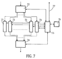
- One intended for the function of the LLC layer Circuit, hereinafter referred to as LLC circuit is in FIG. 7 shown.
- This contains an evaluation circuit 72 and a plurality of buffer memories 73 (first buffer memory), an intermediate memory 74, one for controlling the LLC control circuit provided for various circuit elements of the LLC circuit 75 (first control circuit) and a table memory 76.
- Die Evaluation circuit 72 receives ATM cells from the network interface 23 (FIG. 2) or 59 (FIG. 6) and evaluates, for example, the header field of the incoming cell for forwarding the cell.
- additional information from the Cell added in the evaluation circuit 72 for forwarding is evaluated. Depending on the evaluation of the cell, this is in one or more specific buffer memories 73 are written.
- Control information that the evaluation circuit 72 of the LLC control circuit 75 provides one or more specific buffers 73 through the LLC control circuit 75 approved for registration.
- the function of the buffer memory 73 can be a RAM (Random Access Memory) under appropriate Control of the LLC control circuit 75 can be realized.
- n Buffer memories are therefore for one Single or unicast connection or a multiple or multicast connection intended.
- a multicast connection one in the evaluation circuit 72 incoming cell according to the number of through the multicast connection predetermined connections and copied into the corresponding buffer memory registered.
- Another buffer is for a distribution or cells Broadcast connection provided.
- the LLC circuit which is located in a radio device 49 of a terminal 9 to 21 has a buffer memory because of the connection to other terminals in the radio coverage area of the assigned network interface (1 to 8) and to Terminals of other network interfaces (1 to 8) via the assigned network interface is handled. Otherwise, the LLC circuit of a terminal 9 to 21 shows the same circuit elements and functions as the LLC circuit 7.
- n is equal to the number of terminals in the 5 (n-1) buffer memories are used for buffering cells for a single or unicast connection or Multiple or multicast connection to (n - 1) other terminals.
- n is equal to the number of terminals in the 5 (n-1) buffer memories are used for buffering cells for a single or unicast connection or Multiple or multicast connection to (n - 1) other terminals.
- At a multicast connection is one that arrives in the evaluation circuit 72 Cell corresponding to the number of those specified by the multicast connection Connections copied and written into the corresponding buffer memory.
- For Buffering cells for a distribution or broadcast connection is another Buffer memory determined.
- the reading of the cells from the respective buffer memories 73 of FIG of the LLC control circuit 75 The read cells are in the Buffer 74 temporarily stored. There is no buffering of cells made, but overwrite the newly registered cells possibly still existing cells. However, a copy of the cell remains in a buffer memory 73 until the proper reception of which the cell receiving radio device (e.g. 49) has been confirmed.
- One in one Buffer memory 73 cell is deleted by the LLC control circuit 75, when proper receipt has been confirmed. Another delete process is performed when a cell's stay a predetermined buffering time (timeout) exceeds. If the confirmation of receipt of a cell not within a waiting time adapted to the transmission speed or the cell is received as improper within the Buffering time has been confirmed, the transmission of the cell is repeated.
- the LLC control circuit 75 carries out a sorting of the cells in a respective buffer memory 73, specifically when a cell has been supplied by the evaluation circuit 72.
- Cells in a buffer memory can belong to different virtual connections and therefore have different, maximum permitted buffering times.
- a buffering time for a voice connection is usually much less (or zero) than a buffering time for a data connection, for example between two personal computers.
- the variable RL corresponds to the remaining lifetime
- the variable ML corresponds to the maximum delay
- the variable CT the time of the Calculation (current time)
- the maximum dwell time is always longer than the buffering time.
- the Sorting is carried out according to the remaining lifetime, i.e. the cell with the Least remaining life is the cell that then comes from a buffer memory 73 is read out first. If a cell from a buffer memory 73 before the sorting has been read out and a confirmation of the correct Reception has not yet arrived or the specified waiting time for the confirmation has not yet expired, this cell will not be in the Sorting process is included and is the cell, which is then first read out again becomes.
- Each cell are under the logical number of the virtual connection (Combination of VPI and VCI) further parameters assigned, such as a Destination, a buffering time and a maximum stay.
- these parameters can be used to control the LLC 75 via a further connection 77, which is an interface between a Network interface 23 or 59 and the LLC circuit indicates, or by means of Control cells are transferred. If the evaluation circuit 72 such Control cells recognizes, these are passed directly to the LLC control circuit 75.
- the parameters received by the LLC control circuit 75 are under the corresponding logical number of the virtual connection in the Table memory 76 stores. It is also possible to set these parameters for each one Append cell in the respective buffer memories 73 as additional information. In In this case, the table memory 76 can then be omitted.
- the parameters assigned to the cell, maximum dwell time, buffering time and Storage time can be stored with, in order to have faster access to the to enable corresponding data. It is also possible to save the time in the table memory or another associated with the LLC control circuit 75 Store memory. It should be noted that the LLC control circuit 75 as Micro or signal processor designed with appropriate peripheral elements can be.
- the cells from the buffer memories 73 each become uniform read out.
- several buffer memories can be preferred during the reading will.
- the LLC circuit is therefore intended to carry out a flow and error control.
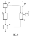
- a circuit which is coupled to the LLC circuit and is intended for the function of the MAC layer and is referred to below as the MAC circuit is shown in FIG. 8.
- the MAC circuit enables collision-free multiple access to the radio transmission medium.
- the cells emitted by the buffer memory 74 of the LLC circuit are fed to a further evaluation circuit 78 of the MAC circuit, which also has a further buffer memory 79 (second buffer memory), a further buffer memory 80, a MAC provided for controlling the various circuit elements of the MAC circuit.
- Control circuit 81 (second control circuit) and a further table memory 82.
- the cells received by the evaluation circuit 78 are written into the buffer memory 79 after the evaluation.
- the MAC control circuit 81 controls the writing process into the buffer memory 79.
- the MAC control circuit 81 carries out a sorting according to the remaining lifetime.
- variable RL corresponds to the remaining lifetime
- variable ML the maximum delay
- CT the time of the Calculation (current time)
- AT the storage time (arrival time).
- a cell that is about to be transferred is in the sorting process not included.
- the MAC circuit does not repeat the Cell transmission through.
- the second buffer memory 79 is used only for buffering of cells until a MAC control device releases the broadcast allowed certain cells.
- the MAC-MAC control device can at Use of the MAC circuit in a network interface of the local 1 either the control arrangement 40 or the MAC control circuit Be 81.
- the MAC control device is either the control arrangement 61 or the MAC control circuit 81. In the latter case, the terminal is the controller.
- the MAC circuit which is in a radio device 49 of a terminal 9 to 21 is also has a second buffer memory.
- the connection to other terminals in the radio coverage area of the assigned network interface (1 to 8) and to terminals of other network interfaces (1 to 8) can via the assigned network interface is processed.
- the MAC circuit of one Terminals 9 to 21 are constructed in exactly the same way as the MAC circuit according to FIG. 8 MAC circuitry of a radio 49 receives a time slot assignment from the MAC control device of the assigned network interface.
- a terminal of the local network according to Fig. 5, which is not the controller forms a time slot allocation from the MAC-MAC controller of the assigned controller.
- the MAC-MAC control device 1 and the controller 5 is of course also for the time slot allocation to the assigned (own) MAC circuit responsible, if this intends cells to send out yourself.
- the table memory 82 there are one under the logical number (VPI and VCI) two parameters stored in the virtual connection. That is the destination of the Cell and the maximum permissible length of stay.
- the parameters are stored in the table memory 82.
- the parameters can also as additional information together with the assigned cell via the Evaluation circuit 78 are supplied and buffered in the buffer memory 79. In this case, the table memory 82 can be omitted.
- the Buffer memory 79 further parameters, such as the time of storage as Additional information can be stored.
- Dynamic time slot allocation is carried out in the MAC circuit.
- the MAC control circuit 81 shares the assigned MAC control device with how many cells for which destination in the second buffer memory 79 are saved.
- the MAC control device performs an optimization regarding the cells to be transmitted that are desired by the various terminals and then assigns time slots to the terminals to a specific frame. After the allocation of at least one time slot becomes the number of time slots and cells corresponding to the duration of a time slot to the allocated one The time of the frame is read out of the buffer memory 79 and sent to the Modern 52 delivered.
Landscapes
- Engineering & Computer Science (AREA)
- Computer Networks & Wireless Communication (AREA)
- Signal Processing (AREA)
- Mobile Radio Communication Systems (AREA)
- Data Exchanges In Wide-Area Networks (AREA)
- Small-Scale Networks (AREA)
Abstract
Description
- Fig. 1
- ein lokales Netzwerk,
- Fig. 2
- eine in dem lokalen Netzwerk nach Fig. 1 verwendbare Netzwerkschnittstelle,
- Fig. 3
- ein mit einer Netzwerkschnittstelle nach Fig. 2 über eine Funkstrecke gekoppeltes Terminal,
- Fig. 4
- eine in einer Netzwerkschnittstelle nach Fig. 2 oder einem Terminal nach Fig. 3 enthaltenen Funkvorrichtung,
- Fig. 5
- ein weiters lokales Netzwerk,
- Fig. 6
- ein Blockschaltbild eines im lokalen Netzwerk nach Fig. 5 verwendbaren Terminals,
- Fig. 7
- eine in der Funkvorrichtung nach Fig. 4 enthaltene, für die Funktion der LLC-Schicht vorgesehene Schaltung und
- Fig. 8
- eine in der Funkvorrichtung nach Fig. 4 enthaltene, für die Funktion der MAC-Schicht vorgesehene Schaltung.
Claims (9)
- Lokales, nach dem asynchronen Transfermodus arbeitendes Netzwerk mit einer ersten Sende- und Empfangsvorrichtung (1 bis 8, 54 bis 57), die eine Funkvorrichtung (33,60) zur Übertragung von Zellen an mehrere andere Sende- und Empfangsvorrichtungen (1 bis 21, 54 bis 57) enthält,
dadurch gekennzeichnet,daß die Funkvorrichtung (49, 60) jeweils einer anderen Sende- und Empfangsvorrichtung (1 bis 21, 54 bis 57) zugeordnete erste Pufferspeicher (73) enthält unddaß ein erster Pufferspeicher (73) zur Speicherung einer Zelle vorgesehen ist, deren Bestimmungsort eine andere Sende- und Empfangsvorrichtung (1 bis 21, 54 bis 57) ist, welche dem betreffenden ersten Pufferspeicher (73) zugeordnet ist. - Lokales Netzwerk nach Anspruch 1,
dadurch gekennzeichnet,daß die Funkvorrichtung (49, 60) eine erste Steuerschaltung (75) enthält, die zur Löschung einer Zelle in einem ersten Pufferspeicher (73) nach einer Bestätigung eines ordnungsgemäßen Empfangs einer zugeordneten Empfangsvorrichtung vorgesehen (1 bis 21, 54 bis 57) ist. - Lokales Netzwerk nach Anspruch 2,
dadurch gekennzeichnet,daß nach dem Einschreiben einer Zelle in einem ersten Pufferspeicher (73) die erste Steuerschaltung (75) zur Sortierung der Zellen in dem betreffenden ersten Pufferspeicher (73) nach der restlichen Lebenszeit vorgesehen ist,daß die erste Steuerschaltung (75) zur Berechnung der restliche Lebenszeit einer Zelle durch Subtraktion des Zeitpunktes der Berechnung und Addition des Speicher zeitpunktes von der vorgegebenen maximalen Verweildauer vorgesehen ist unddäß die erste Steuerschaltung (75) zur Freigabe der Auslesung der Zelle mit der geringsten restlichen Lebenszeit aus einem ersten Pufferspeicher (73) vorgesehen ist. - Lokales Netzwerk nach Anspruch 3,
dadurch gekennzeichnet,daß die erste Steuerschaltung (75) nicht zur Sortierung solcher Zellen vorgesehen ist, bei denen nach einer Auslesung aus einem ersten Pufferspeicher (73) noch nicht eine Bestätigung über den Empfang innerhalb einer Pufferungszeit eingetroffen ist oder die Wartezeit für eine Bestätigung noch nicht abgelaufen ist. - Lokales Netzwerk nach Anspruch 4,
dadurch gekennzeichnet,daß ein zweiter Pufferspeicher (79) zum Empfang einer aus einem ersten Pufferspeicher (73) ausgelesenen Zelle vorgesehen ist unddaß eine zweite Steuerschaltung (81) zur Sortierung der im zweiten Pufferspeicher (79) gepufferten Zellen nach der restlichen Lebenszeit vorgesehen ist. - Lokales Netzwerk nach Anspruch 5,
dadurch gekennzeichnet,daß die zweite Steuerschaltung (81) zur Zählung der zu einer Sende- und Empfangsvorrichtung (1 bis 21, 54 bis 57) zu sendenden Zellen und zur Weitergabe an eine Kontrollvorrichtung (1 bis 8, 54 bis 57) vorgesehen ist unddaß die Kontrollvorrichtung (1 bis 8, 54 bis 57) zur Zuweisung der Anzahl von Zellen vorgesehen ist, welche zu einer bestimmten Sende- und Empfangsvorrichtung (1 bis 21, 54 bis 57) zu übertragen sind. - Lokales Netzwerk nach einem der Ansprüche 1 bis 6,
dadurch gekennzeichnet,daß die Sende- und Empfangsvorrichtungen (54 bis 57) jeweils ein Terminal mit einer Station (58) und einer Netzwerkschnittstelle (59) bilden, die eine wenigstens zum Verbindungsaufbau vorgesehene Steueranordnung (61) und eine Koppelvorrichtung (62) zur Vermittlung von Zellen zwischen Funkvorrichtung (60), Station (58) und Steueranordnung (61) enthält, unddaß die Terminals (54 bis 57) jeweils zum direkten Datenaustausch mit einem anderen Terminal (54 bis 57) vorgesehen sind. - Lokales Netzwerk nach einem der Ansprüche 1 bis 6,
dadurch gekennzeichnet,daß die erste Sende- und Empfangsvorrichtungen als Netzwerkschnittstelle (1 bis 8) ausgebildet ist, die mit mehreren anderen in einem Ring geschalteten Netzwerkschnittstellen (1 bis 8) gekoppelt ist,daß eine Netzwerkschnittstelle (1 bis 8, 23) eine wenigstens zum Verbindungsaufbau vorgesehene Steueranordnung (40) und eine Koppelvorrichtung (24) zur Vermittlung von Zellen zwischen Ringanschlüssen (29 bis 32), Funkvorrichtung (33) und Steueranordnung (40) enthält unddaß andere Sende- und Empfangsvorrichtungen (9 bis 21) jeweils ein Terminal bilden, welche jeweils zum Austausch von Daten mit einer Netzwerkschnittstelle (1 bis 8) vorgesehen ist. - Funkvorrichtung (33, 60) einer ersten Sende- und Empfangsvorrichtung (1 bis 8, 54 bis 57) in einem lokalen, nach dem asynchronen Transfermodus arbeitenden Netzwerk zur Übertragung von Zellen an mehrere andere Sende- und Empfangsvorrichtungen (1 bis 21, 54 bis 57),
dadurch gekennzeichnet,däß die Funkvorrichtung (49, 60) jeweils einer anderen Sende- und Empfangsvorrichtung (1 bis 21, 54 bis 57) zugeordnete erste Pufferspeicher (73) enthält unddaß ein erster Pufferspeicher (73) zur Speicherung einer Zelle vorgesehen ist, deren Bestimmungsort eine andere Sende- und Empfangsvorrichtung (1 bis 21, 54 bis 57) ist, welche dem betreffenden ersten Pufferspeicher (73) zugeordnet ist.
Applications Claiming Priority (2)
| Application Number | Priority Date | Filing Date | Title |
|---|---|---|---|
| DE19639845A DE19639845C1 (de) | 1996-09-27 | 1996-09-27 | Lokales Netzwerk mit Sende- und Empfangsvorrichtung |
| DE19639845 | 1996-09-27 |
Publications (3)
| Publication Number | Publication Date |
|---|---|
| EP0833542A2 true EP0833542A2 (de) | 1998-04-01 |
| EP0833542A3 EP0833542A3 (de) | 1999-10-06 |
| EP0833542B1 EP0833542B1 (de) | 2006-12-13 |
Family
ID=7807137
Family Applications (1)
| Application Number | Title | Priority Date | Filing Date |
|---|---|---|---|
| EP97202892A Expired - Lifetime EP0833542B1 (de) | 1996-09-27 | 1997-09-22 | Lokales Netzwerk mit Sende- und Empfangsvorrichtung |
Country Status (5)
| Country | Link |
|---|---|
| US (1) | US6088346A (de) |
| EP (1) | EP0833542B1 (de) |
| JP (1) | JPH10190708A (de) |
| KR (1) | KR100596946B1 (de) |
| DE (2) | DE19639845C1 (de) |
Families Citing this family (22)
| Publication number | Priority date | Publication date | Assignee | Title |
|---|---|---|---|---|
| US6711140B1 (en) * | 1997-07-15 | 2004-03-23 | Comsat Corporation | Method and apparatus for fast acquisition and synchronization of transmission frames |
| JP4112020B2 (ja) * | 1998-01-16 | 2008-07-02 | シンボル テクノロジーズ インコーポレイテッド | 無線lan用インフラストラクチャ |
| JP3711432B2 (ja) * | 1998-04-15 | 2005-11-02 | セイコーエプソン株式会社 | 周辺処理装置およびその制御方法 |
| FR2783382B1 (fr) * | 1998-09-11 | 2000-10-20 | France Telecom | Reseau d'acces pour des terminaux mobiles |
| DE19848340A1 (de) * | 1998-10-21 | 2000-04-27 | Philips Corp Intellectual Pty | Lokales Netzwerk mit Brücken-Terminal zur Übertragung von Daten zwischen mehreren Sub-Netzwerken |
| US6560652B1 (en) * | 1998-11-20 | 2003-05-06 | Legerity, Inc. | Method and apparatus for accessing variable sized blocks of data |
| JP2000347980A (ja) * | 1999-03-29 | 2000-12-15 | Canon Inc | 周辺装置、周辺装置の制御方法、記憶媒体、及び、情報処理システム |
| US6545993B1 (en) * | 1999-06-28 | 2003-04-08 | Legerity, Inc. | Method and apparatus for managing data transfer and acknowledgements |
| US7173923B2 (en) * | 2000-03-17 | 2007-02-06 | Symbol Technologies, Inc. | Security in multiple wireless local area networks |
| US7173922B2 (en) * | 2000-03-17 | 2007-02-06 | Symbol Technologies, Inc. | Multiple wireless local area networks occupying overlapping physical spaces |
| KR20020026657A (ko) * | 2000-10-02 | 2002-04-12 | 유태로 | 패킷 라우터를 사용하는 근거리 통신망과의 통신 선로를제공하는 차세대 이동통신망에서의 기지국 |
| US7627887B2 (en) * | 2001-04-30 | 2009-12-01 | Scientific- Atlanta, Inc. | System and method for multicasting packets in a subscriber network |
| US7197024B2 (en) * | 2001-06-27 | 2007-03-27 | Lucent Technologies Inc. | Telecommunications system having layered protocol with delimiter of payload |
| EP1276262A1 (de) * | 2001-07-10 | 2003-01-15 | Lucent Technologies Inc. | Kommunikationsringnetzwerk mit Datentrennung in den Knoten |
| US7500261B1 (en) * | 2001-10-30 | 2009-03-03 | Sprint Communications Company L.P. | Multi-point multi-channel data distribution system |
| US6798761B2 (en) * | 2002-01-10 | 2004-09-28 | Harris Corporation | Method and device for establishing communication links and handling SP slot connection collisions in a communication system |
| JP2003338837A (ja) * | 2002-05-22 | 2003-11-28 | Fujitsu Ltd | パケット通信システムにおける通信品質保証方法及び転送遅延保証機能付きパケット通信装置 |
| TW579158U (en) * | 2002-10-16 | 2004-03-01 | Lite On Technology Corp | Module for increasing range of IR emission and reception |
| WO2004107174A1 (en) * | 2003-05-28 | 2004-12-09 | Symbol Technologies, Inc. | Backup cell controller |
| WO2004107638A2 (en) * | 2003-05-28 | 2004-12-09 | Symbol Technologies, Inc. | Improved wireless network cell controller |
| WO2005114443A2 (en) * | 2004-04-23 | 2005-12-01 | Thomson Licensing S.A. | Infrared data association object network storage device |
| US7760695B2 (en) * | 2006-09-29 | 2010-07-20 | Symbol Technologies, Inc. | Methods and systems for centralized cluster management in wireless switch architecture |
Family Cites Families (5)
| Publication number | Priority date | Publication date | Assignee | Title |
|---|---|---|---|---|
| DE4329048A1 (de) * | 1993-08-28 | 1995-03-02 | Philips Patentverwaltung | Lokales, nach dem asynchronen Transfermodus (ATM) arbeitendes Netzwerk |
| DE4343839A1 (de) * | 1993-12-22 | 1995-06-29 | Philips Patentverwaltung | Lokales Netzwerk mit einem Datenaustausch über Funkübertragungswege |
| US5640384A (en) * | 1994-06-13 | 1997-06-17 | U.S. Philips Corporation | Reconfigurable communication network |
| US5623495A (en) * | 1995-06-15 | 1997-04-22 | Lucent Technologies Inc. | Portable base station architecture for an AD-HOC ATM lan |
| US5787080A (en) * | 1996-06-03 | 1998-07-28 | Philips Electronics North America Corporation | Method and apparatus for reservation-based wireless-ATM local area network |
-
1996
- 1996-09-27 DE DE19639845A patent/DE19639845C1/de not_active Expired - Fee Related
-
1997
- 1997-09-22 EP EP97202892A patent/EP0833542B1/de not_active Expired - Lifetime
- 1997-09-22 US US08/937,313 patent/US6088346A/en not_active Expired - Lifetime
- 1997-09-22 DE DE59712778T patent/DE59712778D1/de not_active Expired - Fee Related
- 1997-09-25 JP JP26041197A patent/JPH10190708A/ja not_active Ceased
- 1997-09-27 KR KR1019970051125A patent/KR100596946B1/ko not_active Expired - Fee Related
Non-Patent Citations (4)
| Title |
|---|
| AYANOGLU E ET AL: "MOBILE INFORMATION INFRASTRUCTURE" AT & T TECHNICAL JOURNAL, Bd. 1, Nr. 2, 21. September 1996 (1996-09-21), Seiten 143-164, XP000656011 ISSN: 8756-2324 * |
| ENG K Y ET AL: "A WIRELESS BROADBAND AD-HOC ATM LOCAL-AREA NETWORK" WIRELESS NETWORKS, Bd. 1, Nr. 2, 1. Juli 1995 (1995-07-01), Seiten 161-173, XP000524640 ISSN: 1022-0038 * |
| PETRAS D ET AL: "PERFORMANCE EVALUATION OF THE ASR-ARQ PROTOCOL FOR WIRELESS ATM" IEEE 1995 WIRELESS COMMUNICATIONS SYSTEMS SYMPOSIUM PROCEEDINGS, 27. November 1995 (1995-11-27), Seiten 71-77 77, XP002085780 ISSN: 0022-538X * |
| RAYCHAUDHURI D ET AL: "WATMNET: A PROTOTYPE WIRELESS ATM SYSTEM FOR MULTIMEDIA PERSONAL COMMUNICATION" 1996 IEEE INTERNATIONAL CONFERENCE ON COMMUNICATIONS (ICC), CONVERGING TECHNOLOGIES FOR TOMORROW'S APPLICATIONS DALLAS, JUNE 23 - 27, 1996, Bd. 1, 23. Juni 1996 (1996-06-23), Seiten 469-477, XP000625717 INSTITUTE OF ELECTRICAL & ELECTRONICS ENGINEERSISBN: 0-7803-3251-2 * |
Also Published As
| Publication number | Publication date |
|---|---|
| US6088346A (en) | 2000-07-11 |
| KR19980025180A (ko) | 1998-07-06 |
| DE19639845C1 (de) | 1998-04-02 |
| EP0833542B1 (de) | 2006-12-13 |
| DE59712778D1 (de) | 2007-01-25 |
| KR100596946B1 (ko) | 2006-10-04 |
| EP0833542A3 (de) | 1999-10-06 |
| JPH10190708A (ja) | 1998-07-21 |
Similar Documents
| Publication | Publication Date | Title |
|---|---|---|
| DE19639845C1 (de) | Lokales Netzwerk mit Sende- und Empfangsvorrichtung | |
| EP0996257B1 (de) | Netzwerk mit Brücken-Terminal zur Übertragung von Daten zwischen mehreren Sub-Netzwerken | |
| DE69835809T2 (de) | Kommunikationssteuereinheit und Kommunikationssteuerungsverfahren angewendet für ein Mehrfachsende-unterstützendes LAN | |
| DE19848993B4 (de) | ATM-Kommunikationsnetz, ATM-Kommunikationsschalter und Verfahren zum Lenken eines Stroms von ATM-Zellen | |
| DE4329048A1 (de) | Lokales, nach dem asynchronen Transfermodus (ATM) arbeitendes Netzwerk | |
| EP0920233A2 (de) | Drahtloses lokales Netzwerk mit Controller und wenigstens einem als Controller einsetzbaren Terminal | |
| EP0660567B1 (de) | Lokales Netzwerk | |
| EP0831620A2 (de) | Lokales Netzwerk mit zur Funkübertragung vorgesehenen Terminals | |
| EP0996258A2 (de) | Lokales Netzwerk mit einem Brücken-Terminal zur Übertragung von Daten zwischen mehreren Sub-Netzwerken und zur Schleifendetektion | |
| DE19708182C2 (de) | System zur leitungsungebundenen Übertragung eines rahmensynchronisierten Signals zwischen einer Feststation und wenigstens einem mobilen Terminal | |
| DE19636394A1 (de) | Lokales, nach dem asynchronen Transfermodus arbeitendes Netzwerk in Ringstruktur mit drahtlosen Terminals | |
| WO2003055258A1 (de) | Verfahren zum paketvermittelten datenübertragung bei funkzellenwechsel | |
| DE69431859T2 (de) | Burst-Server-Vermittlungssystem und -verfahren | |
| EP2028895A1 (de) | Verfahren und Kommunikationssystem für Multihoming durch einem mobilen Router mit Lastverteilung | |
| EP1049294B1 (de) | Netzwerk mit mehreren Netzwerk-clustern zur drahtlosen Übertragung von Paketen | |
| EP1187397A2 (de) | Neukonfigurierung eines Adhoc-Netzwerks | |
| EP0996259B1 (de) | Automatische Konfigurierung eines Brücken-Terminals zur Uebertragung von Daten zwischen mehreren Sub-Netzwerken in einem lokalen Netzwerk | |
| DE19618950C2 (de) | Verfahren zum Suchen eines Paketübertragungspfads in einem Breitbandinformations- und -kommunikationssystem | |
| DE19715799A1 (de) | Lokales Netzwerk mit Umsetzmitteln | |
| DE19532421C1 (de) | Lokales, nach dem asynchronen Transfermodus (ATM) arbeitendes Netzwerk zur Erzeugung von priorisierten Zellen | |
| EP1139607B1 (de) | Drahtloses Netzwerk mit einem Zeitschlitzsortiermechanismus | |
| EP0913984A2 (de) | Digitales Telekommunikations-System mit DECT-Interface für Fax- und Datenanwendungen | |
| EP0889669B1 (de) | Kommunikationssystem mit Sonderkanal | |
| EP1535435B1 (de) | Verfahren und vorrichtung zum übertragen von dienstgüte- und adressinformationen in einem kommunikationssystem bei bidirektionaler kommunikation | |
| WO2000002412A1 (de) | Verfahren zum einrichten eines leitweges über ein kommunikationsnetz |
Legal Events
| Date | Code | Title | Description |
|---|---|---|---|
| PUAI | Public reference made under article 153(3) epc to a published international application that has entered the european phase |
Free format text: ORIGINAL CODE: 0009012 |
|
| AK | Designated contracting states |
Kind code of ref document: A2 Designated state(s): DE FR GB |
|
| PUAL | Search report despatched |
Free format text: ORIGINAL CODE: 0009013 |
|
| AK | Designated contracting states |
Kind code of ref document: A3 Designated state(s): AT BE CH DE DK ES FI FR GB GR IE IT LI LU MC NL PT SE |
|
| RAP3 | Party data changed (applicant data changed or rights of an application transferred) |
Owner name: KONINKLIJKE PHILIPS ELECTRONICS N.V. Owner name: PHILIPS CORPORATE INTELLECTUAL PROPERTY GMBH |
|
| 17P | Request for examination filed |
Effective date: 20000406 |
|
| AKX | Designation fees paid |
Free format text: DE FR GB |
|
| RAP1 | Party data changed (applicant data changed or rights of an application transferred) |
Owner name: KONINKLIJKE PHILIPS ELECTRONICS N.V. Owner name: PHILIPS CORPORATE INTELLECTUAL PROPERTY GMBH |
|
| RAP1 | Party data changed (applicant data changed or rights of an application transferred) |
Owner name: KONINKLIJKE PHILIPS ELECTRONICS N.V. Owner name: PHILIPS INTELLECTUAL PROPERTY & STANDARDS GMBH |
|
| GRAC | Information related to communication of intention to grant a patent modified |
Free format text: ORIGINAL CODE: EPIDOSCIGR1 |
|
| GRAP | Despatch of communication of intention to grant a patent |
Free format text: ORIGINAL CODE: EPIDOSNIGR1 |
|
| GRAS | Grant fee paid |
Free format text: ORIGINAL CODE: EPIDOSNIGR3 |
|
| GRAA | (expected) grant |
Free format text: ORIGINAL CODE: 0009210 |
|
| AK | Designated contracting states |
Kind code of ref document: B1 Designated state(s): DE FR GB |
|
| REG | Reference to a national code |
Ref country code: GB Ref legal event code: FG4D Free format text: NOT ENGLISH |
|
| REF | Corresponds to: |
Ref document number: 59712778 Country of ref document: DE Date of ref document: 20070125 Kind code of ref document: P |
|
| GBT | Gb: translation of ep patent filed (gb section 77(6)(a)/1977) |
Effective date: 20070208 |
|
| ET | Fr: translation filed | ||
| PLBE | No opposition filed within time limit |
Free format text: ORIGINAL CODE: 0009261 |
|
| STAA | Information on the status of an ep patent application or granted ep patent |
Free format text: STATUS: NO OPPOSITION FILED WITHIN TIME LIMIT |
|
| 26N | No opposition filed |
Effective date: 20070914 |
|
| GBPC | Gb: european patent ceased through non-payment of renewal fee |
Effective date: 20070922 |
|
| PG25 | Lapsed in a contracting state [announced via postgrant information from national office to epo] |
Ref country code: DE Free format text: LAPSE BECAUSE OF NON-PAYMENT OF DUE FEES Effective date: 20080401 |
|
| REG | Reference to a national code |
Ref country code: FR Ref legal event code: ST Effective date: 20080531 |
|
| PG25 | Lapsed in a contracting state [announced via postgrant information from national office to epo] |
Ref country code: FR Free format text: LAPSE BECAUSE OF NON-PAYMENT OF DUE FEES Effective date: 20071001 |
|
| PG25 | Lapsed in a contracting state [announced via postgrant information from national office to epo] |
Ref country code: GB Free format text: LAPSE BECAUSE OF NON-PAYMENT OF DUE FEES Effective date: 20070922 |