EP0833727B1 - Verfahren zur herstellung von abstandshalter aus beton und formwerkzeug zu ihrer herstellung - Google Patents
Verfahren zur herstellung von abstandshalter aus beton und formwerkzeug zu ihrer herstellung Download PDFInfo
- Publication number
- EP0833727B1 EP0833727B1 EP95921174A EP95921174A EP0833727B1 EP 0833727 B1 EP0833727 B1 EP 0833727B1 EP 95921174 A EP95921174 A EP 95921174A EP 95921174 A EP95921174 A EP 95921174A EP 0833727 B1 EP0833727 B1 EP 0833727B1
- Authority
- EP
- European Patent Office
- Prior art keywords
- mould
- reinforcement
- production
- spacers
- reinforcement spacers
- Prior art date
- Legal status (The legal status is an assumption and is not a legal conclusion. Google has not performed a legal analysis and makes no representation as to the accuracy of the status listed.)
- Expired - Lifetime
Links
- 230000002787 reinforcement Effects 0.000 title claims description 51
- 125000006850 spacer group Chemical group 0.000 title claims description 51
- 238000004519 manufacturing process Methods 0.000 title claims description 24
- 238000005266 casting Methods 0.000 claims description 13
- 239000011505 plaster Substances 0.000 claims description 9
- 238000000034 method Methods 0.000 claims description 5
- 238000005452 bending Methods 0.000 claims description 3
- 239000000463 material Substances 0.000 claims description 3
- 239000002184 metal Substances 0.000 claims description 3
- 239000013013 elastic material Substances 0.000 claims description 2
- 229910001294 Reinforcing steel Inorganic materials 0.000 description 3
- XLYOFNOQVPJJNP-UHFFFAOYSA-N water Substances O XLYOFNOQVPJJNP-UHFFFAOYSA-N 0.000 description 2
- 239000004809 Teflon Substances 0.000 description 1
- 229920006362 Teflon® Polymers 0.000 description 1
- 230000007797 corrosion Effects 0.000 description 1
- 238000005260 corrosion Methods 0.000 description 1
- -1 e.g. Substances 0.000 description 1
- 238000009415 formwork Methods 0.000 description 1
- 239000011810 insulating material Substances 0.000 description 1
- 239000000203 mixture Substances 0.000 description 1
- 238000000465 moulding Methods 0.000 description 1
- 230000035515 penetration Effects 0.000 description 1
- 230000000704 physical effect Effects 0.000 description 1
- 239000004033 plastic Substances 0.000 description 1
- 239000002023 wood Substances 0.000 description 1
Images

Classifications
-
- B—PERFORMING OPERATIONS; TRANSPORTING
- B28—WORKING CEMENT, CLAY, OR STONE
- B28B—SHAPING CLAY OR OTHER CERAMIC COMPOSITIONS; SHAPING SLAG; SHAPING MIXTURES CONTAINING CEMENTITIOUS MATERIAL, e.g. PLASTER
- B28B7/00—Moulds; Cores; Mandrels
- B28B7/34—Moulds, cores, or mandrels of special material, e.g. destructible materials
- B28B7/348—Moulds, cores, or mandrels of special material, e.g. destructible materials of plastic material or rubber
-
- B—PERFORMING OPERATIONS; TRANSPORTING
- B28—WORKING CEMENT, CLAY, OR STONE
- B28B—SHAPING CLAY OR OTHER CERAMIC COMPOSITIONS; SHAPING SLAG; SHAPING MIXTURES CONTAINING CEMENTITIOUS MATERIAL, e.g. PLASTER
- B28B7/00—Moulds; Cores; Mandrels
- B28B7/0064—Moulds characterised by special surfaces for producing a desired surface of a moulded article, e.g. profiled or polished moulding surfaces
-
- B—PERFORMING OPERATIONS; TRANSPORTING
- B28—WORKING CEMENT, CLAY, OR STONE
- B28B—SHAPING CLAY OR OTHER CERAMIC COMPOSITIONS; SHAPING SLAG; SHAPING MIXTURES CONTAINING CEMENTITIOUS MATERIAL, e.g. PLASTER
- B28B7/00—Moulds; Cores; Mandrels
- B28B7/16—Moulds for making shaped articles with cavities or holes open to the surface, e.g. with blind holes
- B28B7/18—Moulds for making shaped articles with cavities or holes open to the surface, e.g. with blind holes the holes passing completely through the article
-
- B—PERFORMING OPERATIONS; TRANSPORTING
- B28—WORKING CEMENT, CLAY, OR STONE
- B28B—SHAPING CLAY OR OTHER CERAMIC COMPOSITIONS; SHAPING SLAG; SHAPING MIXTURES CONTAINING CEMENTITIOUS MATERIAL, e.g. PLASTER
- B28B7/00—Moulds; Cores; Mandrels
- B28B7/34—Moulds, cores, or mandrels of special material, e.g. destructible materials
- B28B7/346—Manufacture of moulds
-
- E—FIXED CONSTRUCTIONS
- E04—BUILDING
- E04C—STRUCTURAL ELEMENTS; BUILDING MATERIALS
- E04C5/00—Reinforcing elements, e.g. for concrete; Auxiliary elements therefor
- E04C5/16—Auxiliary parts for reinforcements, e.g. connectors, spacers, stirrups
- E04C5/20—Auxiliary parts for reinforcements, e.g. connectors, spacers, stirrups of material other than metal or with only additional metal parts, e.g. concrete or plastics spacers with metal binding wires
Definitions
- the present invention concerns a method for production of reinforcement spacers in concrete for use in steel-armoured concrete structures, together with a mould for use in production of the reinforcement spacers (see f.i. document DE-A-2 522 018).
- Reinforcement spacers are used in order to position reinforcement steel which is provided in casting moulds, both before and during filling of the casting moulds with concrete.
- the reinforcement spacers can be made of various materials, such as, e.g., plastic, extruded concrete.
- the problems involved in using known reinforcement spacers can be divided into the following two categories:
- the object of the present invention is to provide a method for production of reinforcement spacers which avoids the above-mentioned disadvantages, and a mould for use in connection with the method.
- the design according to the invention increases the contact surface between concrete and reinforcement spacer, and by means of cut-outs and through-going holes the reinforcement spacer is secured against sliding out of the completed concrete structure.
- the principle of the invention consists in the fact that the method for production of reinforcement spacers for use in steel-armoured concrete structures and the casting mould for use in the production of the reinforcement spacers is designed in such a manner that completed reinforcement spacers both with cut-outs and holes can be removed without having to destroy the casting mould.
- Fig. 1 illustrates a reinforcement spacer 1 which consists of a base part 2 to abut against the foundation and which in a first upper surface 3, opposite the base part 2, is provided with a cut-out or recess to abut against a reinforcement steel (not shown), and where in a second upper surface, opposite the base part 2, there is provided a through-going hole 4 for mounting it on to the foundation, e.g. by means of nails.
- a through-going hole 5 in the area of the cut-out 3, for mounting the reinforcement spacer 1 by means of binding wire to the reinforcement bar.
- the reinforcement spacer 1 is also provided with further cut-outs or grooves 6 and recesses 7 in order to increase the contact surface between reinforcement spacer and concrete and thereby provide maximum binding power to the surrounding concrete.
- one of the largest side surfaces is completely flat.
- the base part 2 is designed with least possible contact with the formwork in order to reduce the surface of the part of the reinforcement spacer which will be aligned with the completed concrete, and thereby reduce the penetration of moisture between reinforcement spacer and the surrounding concrete.
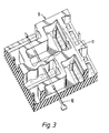
- Fig. 3 is a partial section of a casting mould 9 for the production of reinforcement spacers in concrete.
- step 1 With respect to steps 1 to 6, these apply to production of the actual rubber mould 9, while step 7 concerns the actual production of reinforcement spacers in concrete for use in steel-armoured concrete structures.
- reinforcement spacers are cast in moulds made of two-component rubber mass, which makes the casting moulds very flexible, it is thereby possible to produce reinforcement spacers supplied with cut-outs 6, recesses 7 and through-going holes 4,5, while at the same time the nature of the rubber moulds as opposed to known designs permits the moulds to be re-used.
- the strength of the reinforcement spacers is particularly due to the fact that they are cast in moulds of heat-insulating materials, and thus maintain a stable temperature during the hardening process.
Landscapes
- Engineering & Computer Science (AREA)
- Manufacturing & Machinery (AREA)
- Chemical & Material Sciences (AREA)
- Ceramic Engineering (AREA)
- Mechanical Engineering (AREA)
- Architecture (AREA)
- Civil Engineering (AREA)
- Structural Engineering (AREA)
- Manufacturing Of Tubular Articles Or Embedded Moulded Articles (AREA)
- Reinforcement Elements For Buildings (AREA)
- Forms Removed On Construction Sites Or Auxiliary Members Thereof (AREA)
Claims (5)
- Verfahren zur Herstellung von Verstärkungs-Abstandshaltern aus Beton zur Verwendung in stahlbewehrten Betonstrukturen, dadurch gekennzeichnet, daß die Verstärkungs-Abstandshalter in einer Form aus einem Material gegossen werden, das elastisch, vorzugsweise eine Zwei-Komponenten-Gummimasse ist und daß nach dem Härten die Verstärkungs-Abstandshalter durch elastisches Biegen der Wandteile der Form entfernt werden.
- Verfahren nach Anspruch 1, dadurch gekennzeichnet, daß die Verstärkungs-Abstandshalter in einer Form gegossen werden, die ausgebildet wird durch Gießen der Wände der Form in einem Kasten bzw. Rahmen, in dem ein oder mehrere Modelle, beispielsweise Gipsmodelle der Verstärkungs-Abstandshalter vorhanden sind.
- Form zur Verwendung bei der Herstellung von Verstärkungs-Abstandshaltern nach Anspruch 1, wobei die Form Wände hat, die angepaßt sind an die Form der Verstärkungs-Abstandshalter, dadurch gekennzeichnet, daß sie aus einem elastischen Material, insbesondere einer Zwei-Komponenten-Gummimasse hergestellt ist.
- Form nach Anspruch 3, dadurch gekennzeichnet, daß eine entfernbare Metallstange senkrecht durch die Wandteile der Form vorgesehen ist, zur Herstellung durchgehender Montagelöcher in dem Verstärkungs-Abstandshalter.
- Form nach Anspruch 3, dadurch gekennzeichnet, daß sie derart ausgestaltet ist, daß mit ihr mehrere Verstärkungs-Abstandshalter gleichzeitig gießbar sind.
Applications Claiming Priority (3)
| Application Number | Priority Date | Filing Date | Title |
|---|---|---|---|
| NO940755A NO179291C (no) | 1994-03-04 | 1994-03-04 | Armeringsstoler i formstöpt betong |
| PCT/NO1995/000082 WO1996037351A1 (en) | 1994-03-04 | 1995-05-26 | A method for production of reinforcement chairs and a mould for use in the production |
| CA002219825A CA2219825C (en) | 1994-03-04 | 1995-05-26 | A method for production of reinforcement chairs and a mould for use in the production |
Publications (2)
| Publication Number | Publication Date |
|---|---|
| EP0833727A1 EP0833727A1 (de) | 1998-04-08 |
| EP0833727B1 true EP0833727B1 (de) | 2000-10-04 |
Family
ID=27170507
Family Applications (1)
| Application Number | Title | Priority Date | Filing Date |
|---|---|---|---|
| EP95921174A Expired - Lifetime EP0833727B1 (de) | 1994-03-04 | 1995-05-26 | Verfahren zur herstellung von abstandshalter aus beton und formwerkzeug zu ihrer herstellung |
Country Status (5)
| Country | Link |
|---|---|
| EP (1) | EP0833727B1 (de) |
| CA (1) | CA2219825C (de) |
| FI (1) | FI974324A7 (de) |
| NO (1) | NO179291C (de) |
| WO (1) | WO1996037351A1 (de) |
Family Cites Families (3)
| Publication number | Priority date | Publication date | Assignee | Title |
|---|---|---|---|---|
| DE2522018A1 (de) * | 1975-05-17 | 1976-12-02 | Paech Peter | Abstandshalter fuer armierungselemente im betonbau oder in betonfertigteilen |
| DE2540065A1 (de) * | 1975-09-09 | 1977-03-17 | Fritz Koehlmann | Verfahren und vorrichtung zum verlegen von stahlgewebearmierungen unter verwendung von betonduebeln |
| DE2846391A1 (de) * | 1978-10-25 | 1980-05-08 | Dasag Deutsche Naturasphalt Gm | Ruettelform, insbesondere fuer betonstein-formmaschinen |
-
1994
- 1994-03-04 NO NO940755A patent/NO179291C/no unknown
-
1995
- 1995-05-26 WO PCT/NO1995/000082 patent/WO1996037351A1/en not_active Ceased
- 1995-05-26 CA CA002219825A patent/CA2219825C/en not_active Expired - Fee Related
- 1995-05-26 EP EP95921174A patent/EP0833727B1/de not_active Expired - Lifetime
-
1997
- 1997-11-25 FI FI974324A patent/FI974324A7/fi unknown
Also Published As
| Publication number | Publication date |
|---|---|
| NO940755D0 (no) | 1994-03-04 |
| FI974324A0 (fi) | 1997-11-25 |
| FI974324A7 (fi) | 1997-11-25 |
| EP0833727A1 (de) | 1998-04-08 |
| CA2219825C (en) | 2001-05-22 |
| WO1996037351A1 (en) | 1996-11-28 |
| CA2219825A1 (en) | 1996-11-28 |
| NO179291C (no) | 1996-09-11 |
| NO179291B (no) | 1996-06-03 |
| NO940755L (no) | 1995-09-05 |
Similar Documents
| Publication | Publication Date | Title |
|---|---|---|
| FI87677B (fi) | Isolerad vaegg | |
| CN101356317A (zh) | 具有使用钢管的连接结构的预制混凝土墩砌块的构造方法 | |
| CA2219825C (en) | A method for production of reinforcement chairs and a mould for use in the production | |
| US20090255211A1 (en) | Method and means for producing a concrete block | |
| AU706603B2 (en) | A method for production of reinforcement chairs and a mould for use in the production | |
| JP2974605B2 (ja) | トンネル覆工用セグメントの製造方法 | |
| RU88603U1 (ru) | Форма для производства фигурного стенового блока | |
| ATE135072T1 (de) | Verfahren zur herstellung eines wärmegedämpften/wärmedämpfbaren verstärkten betonbauelementes | |
| JPS60236707A (ja) | 形材 | |
| JP3079016B2 (ja) | 溝模様付コンクリート部材の成形方法及び溝模様形成具 | |
| JP3497118B2 (ja) | 窯業系建築板用型及び該型を用いた窯業系建築板の製造方法 | |
| JP2556952B2 (ja) | 筒状コンクリート製品の製造方法 | |
| JP4169253B2 (ja) | コンクリートブロックの製造方法 | |
| JP2004181736A (ja) | 打ち放し仕上げ調面を有するプレキャストコンクリート板の製造方法及びそれに用いる型材 | |
| KR20180033749A (ko) | 콘크리트 요철판를 이용한 타설 시기를 달리하는 콘크리트 연결면 시공방법 | |
| JPH07238615A (ja) | 鉄筋ユニットと鉄筋内蔵型プレキャスト型枠と鉄筋内蔵型プレキャスト型枠の製造方法 | |
| JPH048514A (ja) | 透水性側溝蓋の製造方法 | |
| JP2539942B2 (ja) | 折曲げ可能なpc型枠およびその製造方法 | |
| JPH0752134A (ja) | コンクリート製品用型枠 | |
| JPS60250910A (ja) | 複合コンクリ−ト製品の製法及び製造装置 | |
| JPS60214907A (ja) | 造形物 | |
| JPS61254302A (ja) | タイル埋込みコンクリ−ト板の製造法 | |
| JPS62268610A (ja) | コンクリ−トブロツクおよびその製造方法 | |
| JPS6337902A (ja) | コンクリ−ト製品の製造方法 | |
| JPH07137023A (ja) | 筒状コンクリート製品の製造方法 |
Legal Events
| Date | Code | Title | Description |
|---|---|---|---|
| PUAI | Public reference made under article 153(3) epc to a published international application that has entered the european phase |
Free format text: ORIGINAL CODE: 0009012 |
|
| 17P | Request for examination filed |
Effective date: 19971223 |
|
| AK | Designated contracting states |
Kind code of ref document: A1 Designated state(s): AT BE CH DE DK ES FR GB GR IE IT LI LU MC NL PT SE |
|
| AX | Request for extension of the european patent |
Free format text: LT PAYMENT 971223;LV PAYMENT 971223 |
|
| RTI1 | Title (correction) |
Free format text: A METHOD FOR PRODUCTION OF REINFORCEMENT SPACERS AND A MOULD FOR USE IN THE PRODUCTION |
|
| GRAG | Despatch of communication of intention to grant |
Free format text: ORIGINAL CODE: EPIDOS AGRA |
|
| 17Q | First examination report despatched |
Effective date: 19990713 |
|
| GRAG | Despatch of communication of intention to grant |
Free format text: ORIGINAL CODE: EPIDOS AGRA |
|
| GRAH | Despatch of communication of intention to grant a patent |
Free format text: ORIGINAL CODE: EPIDOS IGRA |
|
| GRAH | Despatch of communication of intention to grant a patent |
Free format text: ORIGINAL CODE: EPIDOS IGRA |
|
| GRAA | (expected) grant |
Free format text: ORIGINAL CODE: 0009210 |
|
| AK | Designated contracting states |
Kind code of ref document: B1 Designated state(s): AT BE CH DE DK ES FR GB GR IE IT LI LU MC NL PT SE |
|
| AX | Request for extension of the european patent |
Free format text: LT PAYMENT 19971223;LV PAYMENT 19971223 |
|
| LTIE | Lt: invalidation of european patent or patent extension | ||
| PG25 | Lapsed in a contracting state [announced via postgrant information from national office to epo] |
Ref country code: NL Free format text: LAPSE BECAUSE OF FAILURE TO SUBMIT A TRANSLATION OF THE DESCRIPTION OR TO PAY THE FEE WITHIN THE PRESCRIBED TIME-LIMIT Effective date: 20001004 Ref country code: LI Free format text: LAPSE BECAUSE OF FAILURE TO SUBMIT A TRANSLATION OF THE DESCRIPTION OR TO PAY THE FEE WITHIN THE PRESCRIBED TIME-LIMIT Effective date: 20001004 Ref country code: IT Free format text: LAPSE BECAUSE OF FAILURE TO SUBMIT A TRANSLATION OF THE DESCRIPTION OR TO PAY THE FEE WITHIN THE PRESCRIBED TIME-LIMIT;WARNING: LAPSES OF ITALIAN PATENTS WITH EFFECTIVE DATE BEFORE 2007 MAY HAVE OCCURRED AT ANY TIME BEFORE 2007. THE CORRECT EFFECTIVE DATE MAY BE DIFFERENT FROM THE ONE RECORDED. Effective date: 20001004 Ref country code: IE Free format text: LAPSE BECAUSE OF NON-PAYMENT OF DUE FEES Effective date: 20001004 Ref country code: FR Free format text: LAPSE BECAUSE OF FAILURE TO SUBMIT A TRANSLATION OF THE DESCRIPTION OR TO PAY THE FEE WITHIN THE PRESCRIBED TIME-LIMIT Effective date: 20001004 Ref country code: ES Free format text: THE PATENT HAS BEEN ANNULLED BY A DECISION OF A NATIONAL AUTHORITY Effective date: 20001004 Ref country code: CH Free format text: LAPSE BECAUSE OF FAILURE TO SUBMIT A TRANSLATION OF THE DESCRIPTION OR TO PAY THE FEE WITHIN THE PRESCRIBED TIME-LIMIT Effective date: 20001004 Ref country code: BE Free format text: LAPSE BECAUSE OF FAILURE TO SUBMIT A TRANSLATION OF THE DESCRIPTION OR TO PAY THE FEE WITHIN THE PRESCRIBED TIME-LIMIT Effective date: 20001004 Ref country code: AT Free format text: LAPSE BECAUSE OF FAILURE TO SUBMIT A TRANSLATION OF THE DESCRIPTION OR TO PAY THE FEE WITHIN THE PRESCRIBED TIME-LIMIT Effective date: 20001004 |
|
| REF | Corresponds to: |
Ref document number: 196750 Country of ref document: AT Date of ref document: 20001015 Kind code of ref document: T |
|
| REG | Reference to a national code |
Ref country code: CH Ref legal event code: EP |
|
| REG | Reference to a national code |
Ref country code: IE Ref legal event code: FG4D Free format text: GERMAN |
|
| REF | Corresponds to: |
Ref document number: 69519042 Country of ref document: DE Date of ref document: 20001109 |
|
| PG25 | Lapsed in a contracting state [announced via postgrant information from national office to epo] |
Ref country code: SE Free format text: LAPSE BECAUSE OF FAILURE TO SUBMIT A TRANSLATION OF THE DESCRIPTION OR TO PAY THE FEE WITHIN THE PRESCRIBED TIME-LIMIT Effective date: 20010104 Ref country code: PT Free format text: LAPSE BECAUSE OF FAILURE TO SUBMIT A TRANSLATION OF THE DESCRIPTION OR TO PAY THE FEE WITHIN THE PRESCRIBED TIME-LIMIT Effective date: 20010104 Ref country code: DK Free format text: LAPSE BECAUSE OF FAILURE TO SUBMIT A TRANSLATION OF THE DESCRIPTION OR TO PAY THE FEE WITHIN THE PRESCRIBED TIME-LIMIT Effective date: 20010104 |
|
| PG25 | Lapsed in a contracting state [announced via postgrant information from national office to epo] |
Ref country code: GR Free format text: LAPSE BECAUSE OF FAILURE TO SUBMIT A TRANSLATION OF THE DESCRIPTION OR TO PAY THE FEE WITHIN THE PRESCRIBED TIME-LIMIT Effective date: 20010105 Ref country code: DE Free format text: LAPSE BECAUSE OF FAILURE TO SUBMIT A TRANSLATION OF THE DESCRIPTION OR TO PAY THE FEE WITHIN THE PRESCRIBED TIME-LIMIT Effective date: 20010105 |
|
| NLV1 | Nl: lapsed or annulled due to failure to fulfill the requirements of art. 29p and 29m of the patents act | ||
| EN | Fr: translation not filed | ||
| REG | Reference to a national code |
Ref country code: CH Ref legal event code: PL |
|
| PG25 | Lapsed in a contracting state [announced via postgrant information from national office to epo] |
Ref country code: LU Free format text: LAPSE BECAUSE OF NON-PAYMENT OF DUE FEES Effective date: 20010526 Ref country code: GB Free format text: LAPSE BECAUSE OF NON-PAYMENT OF DUE FEES Effective date: 20010526 |
|
| PG25 | Lapsed in a contracting state [announced via postgrant information from national office to epo] |
Ref country code: MC Free format text: LAPSE BECAUSE OF NON-PAYMENT OF DUE FEES Effective date: 20010531 |
|
| PLBE | No opposition filed within time limit |
Free format text: ORIGINAL CODE: 0009261 |
|
| STAA | Information on the status of an ep patent application or granted ep patent |
Free format text: STATUS: NO OPPOSITION FILED WITHIN TIME LIMIT |
|
| REG | Reference to a national code |
Ref country code: IE Ref legal event code: FD4D |
|
| 26N | No opposition filed | ||
| GBPC | Gb: european patent ceased through non-payment of renewal fee |
Effective date: 20010526 |