EP0834018B1 - Mehrstufiger schraubenspindelverdichter - Google Patents
Mehrstufiger schraubenspindelverdichter Download PDFInfo
- Publication number
- EP0834018B1 EP0834018B1 EP96922831A EP96922831A EP0834018B1 EP 0834018 B1 EP0834018 B1 EP 0834018B1 EP 96922831 A EP96922831 A EP 96922831A EP 96922831 A EP96922831 A EP 96922831A EP 0834018 B1 EP0834018 B1 EP 0834018B1
- Authority
- EP
- European Patent Office
- Prior art keywords
- rotor
- compressor according
- rotors
- bearing tube
- opposite
- Prior art date
- Legal status (The legal status is an assumption and is not a legal conclusion. Google has not performed a legal analysis and makes no representation as to the accuracy of the status listed.)
- Expired - Lifetime
Links
- 238000001816 cooling Methods 0.000 claims abstract description 33
- 239000007788 liquid Substances 0.000 claims description 26
- 238000004140 cleaning Methods 0.000 claims description 13
- 230000002093 peripheral effect Effects 0.000 claims description 11
- 238000006073 displacement reaction Methods 0.000 claims description 6
- 230000005855 radiation Effects 0.000 claims description 4
- 238000010521 absorption reaction Methods 0.000 claims description 3
- 239000000110 cooling liquid Substances 0.000 claims description 3
- 238000005406 washing Methods 0.000 claims description 3
- 238000000034 method Methods 0.000 claims description 2
- 239000011796 hollow space material Substances 0.000 claims 1
- 230000000694 effects Effects 0.000 description 13
- 238000007789 sealing Methods 0.000 description 10
- 238000003860 storage Methods 0.000 description 7
- 230000006835 compression Effects 0.000 description 6
- 238000007906 compression Methods 0.000 description 6
- 230000001737 promoting effect Effects 0.000 description 6
- 239000000126 substance Substances 0.000 description 5
- 230000009467 reduction Effects 0.000 description 4
- 239000000498 cooling water Substances 0.000 description 3
- 230000001419 dependent effect Effects 0.000 description 3
- 238000012423 maintenance Methods 0.000 description 3
- 230000035515 penetration Effects 0.000 description 3
- 238000011109 contamination Methods 0.000 description 2
- 239000002826 coolant Substances 0.000 description 2
- 238000005516 engineering process Methods 0.000 description 2
- 230000005484 gravity Effects 0.000 description 2
- 239000004519 grease Substances 0.000 description 2
- 230000006872 improvement Effects 0.000 description 2
- 238000002347 injection Methods 0.000 description 2
- 239000007924 injection Substances 0.000 description 2
- 230000033001 locomotion Effects 0.000 description 2
- 239000002245 particle Substances 0.000 description 2
- 238000005086 pumping Methods 0.000 description 2
- 239000007787 solid Substances 0.000 description 2
- 239000000243 solution Substances 0.000 description 2
- 230000009471 action Effects 0.000 description 1
- 230000000712 assembly Effects 0.000 description 1
- 238000000429 assembly Methods 0.000 description 1
- 230000008901 benefit Effects 0.000 description 1
- 230000000903 blocking effect Effects 0.000 description 1
- 239000011248 coating agent Substances 0.000 description 1
- 238000000576 coating method Methods 0.000 description 1
- 238000010276 construction Methods 0.000 description 1
- 239000000356 contaminant Substances 0.000 description 1
- 230000010006 flight Effects 0.000 description 1
- 239000012530 fluid Substances 0.000 description 1
- 230000017525 heat dissipation Effects 0.000 description 1
- 230000020169 heat generation Effects 0.000 description 1
- 239000012535 impurity Substances 0.000 description 1
- 230000003993 interaction Effects 0.000 description 1
- 239000010687 lubricating oil Substances 0.000 description 1
- 238000005461 lubrication Methods 0.000 description 1
- 230000000149 penetrating effect Effects 0.000 description 1
- 238000007639 printing Methods 0.000 description 1
- 238000010926 purge Methods 0.000 description 1
- 230000001105 regulatory effect Effects 0.000 description 1
- 238000005096 rolling process Methods 0.000 description 1
- 239000007921 spray Substances 0.000 description 1
- 238000005494 tarnishing Methods 0.000 description 1
Images
Classifications
-
- F—MECHANICAL ENGINEERING; LIGHTING; HEATING; WEAPONS; BLASTING
- F04—POSITIVE - DISPLACEMENT MACHINES FOR LIQUIDS; PUMPS FOR LIQUIDS OR ELASTIC FLUIDS
- F04C—ROTARY-PISTON, OR OSCILLATING-PISTON, POSITIVE-DISPLACEMENT MACHINES FOR LIQUIDS; ROTARY-PISTON, OR OSCILLATING-PISTON, POSITIVE-DISPLACEMENT PUMPS
- F04C18/00—Rotary-piston pumps specially adapted for elastic fluids
- F04C18/08—Rotary-piston pumps specially adapted for elastic fluids of intermeshing-engagement type, i.e. with engagement of co-operating members similar to that of toothed gearing
- F04C18/12—Rotary-piston pumps specially adapted for elastic fluids of intermeshing-engagement type, i.e. with engagement of co-operating members similar to that of toothed gearing of other than internal-axis type
- F04C18/14—Rotary-piston pumps specially adapted for elastic fluids of intermeshing-engagement type, i.e. with engagement of co-operating members similar to that of toothed gearing of other than internal-axis type with toothed rotary pistons
- F04C18/16—Rotary-piston pumps specially adapted for elastic fluids of intermeshing-engagement type, i.e. with engagement of co-operating members similar to that of toothed gearing of other than internal-axis type with toothed rotary pistons with helical teeth, e.g. chevron-shaped, screw type
-
- F—MECHANICAL ENGINEERING; LIGHTING; HEATING; WEAPONS; BLASTING
- F01—MACHINES OR ENGINES IN GENERAL; ENGINE PLANTS IN GENERAL; STEAM ENGINES
- F01C—ROTARY-PISTON OR OSCILLATING-PISTON MACHINES OR ENGINES
- F01C21/00—Component parts, details or accessories not provided for in groups F01C1/00 - F01C20/00
- F01C21/02—Arrangements of bearings
-
- F—MECHANICAL ENGINEERING; LIGHTING; HEATING; WEAPONS; BLASTING
- F04—POSITIVE - DISPLACEMENT MACHINES FOR LIQUIDS; PUMPS FOR LIQUIDS OR ELASTIC FLUIDS
- F04C—ROTARY-PISTON, OR OSCILLATING-PISTON, POSITIVE-DISPLACEMENT MACHINES FOR LIQUIDS; ROTARY-PISTON, OR OSCILLATING-PISTON, POSITIVE-DISPLACEMENT PUMPS
- F04C29/00—Component parts, details or accessories of pumps or pumping installations, not provided for in groups F04C18/00 - F04C28/00
- F04C29/04—Heating; Cooling; Heat insulation
-
- F—MECHANICAL ENGINEERING; LIGHTING; HEATING; WEAPONS; BLASTING
- F04—POSITIVE - DISPLACEMENT MACHINES FOR LIQUIDS; PUMPS FOR LIQUIDS OR ELASTIC FLUIDS
- F04C—ROTARY-PISTON, OR OSCILLATING-PISTON, POSITIVE-DISPLACEMENT MACHINES FOR LIQUIDS; ROTARY-PISTON, OR OSCILLATING-PISTON, POSITIVE-DISPLACEMENT PUMPS
- F04C2240/00—Components
- F04C2240/40—Electric motor
- F04C2240/402—Plurality of electronically synchronised motors
-
- F—MECHANICAL ENGINEERING; LIGHTING; HEATING; WEAPONS; BLASTING
- F04—POSITIVE - DISPLACEMENT MACHINES FOR LIQUIDS; PUMPS FOR LIQUIDS OR ELASTIC FLUIDS
- F04C—ROTARY-PISTON, OR OSCILLATING-PISTON, POSITIVE-DISPLACEMENT MACHINES FOR LIQUIDS; ROTARY-PISTON, OR OSCILLATING-PISTON, POSITIVE-DISPLACEMENT PUMPS
- F04C2240/00—Components
- F04C2240/50—Bearings
- F04C2240/51—Bearings for cantilever assemblies
Definitions
- the invention is therefore based on the object.
- the rotors are independent be cooled by the pumped medium in such a way that good conditions for a slight play between the rotors among themselves and between the rotors and the pump chamber housing can be created without causing susceptible seals requirement.
- the solution according to claim 1 is composed of two components, namely firstly the characteristic. that the displacement rotors are cooled more on the pressure side than on the suction side and secondly, a cooling technology that uses the special design of the rotor bearing.
- Multi-stage rotors are understood to mean those whose screw flights forming the compression chambers revolve the rotor several times. so that several are separated from each other on the suction and pressure side over the rotor length Compression chambers are formed.
- the Screws the associated rotor three times each.
- the number of stages can be accordingly the respective printing area. Preferably at least five levels.
- the invention makes use of a special type of cooling adapted to the type of cooling Technology.
- This type of construction assumes that each displacement rotor is flying on the rotor shaft and at least one bearing surrounding the rotor and projecting into the rotor, stationary bearing tube is stored. Only this is cooled immediately. while the Cooling of the rotor takes place indirectly. that the opposing Circumferential surfaces of the rotor and the bearing body are arranged to be heat-exchangeable are. The bearings and the rotor shaft are cooled particularly well, since the are inside the bearing tube.
- the heat transfer between the opposing surfaces of the rotor and to improve the bearing body these can improve the heat exchange Properties are equipped. So that the convective heat exchange is intensified by mediating the air layer between the surfaces, the gap should not be connected to the suction side but to the pressure side stand.
- the surfaces can also be provided with elevations and depressions, which improve the heat transfer coefficient to the medium in between. Of the the mutual distance between the two surfaces should be as small as possible.
- such a treatment of the surfaces can be provided for the radiation exchange be that they have a high absorption number in the area of heat radiation.
- the heat transfer to the opposing surfaces of the rotor and the Bearing body can also be improved in that the gas located between them is set in flow motion.
- the space can be filled with a Gas source can be contacted.
- the gas flow can be correspondingly lower Choice of gas temperature (cooling if necessary) can also be used for heat dissipation.
- he may have a locking function to protect the storage and drive area Exercise before accessing the medium or substances contained in the medium.
- the gas used is expediently fed to the pressure side of the machine.
- the interacting surfaces of the rotor and Bearing body must be equipped with conveyor elements. This can make it unnecessary to provide an external compressed gas source. This also applies if the gas supplied primarily not for cooling but for locking purposes.
- the promotional effect of the areas can be caused in particular by the fact that they are one-sided or both-sided be equipped with conveyor thread. Instead, or in addition, they can too be conical so that the centrifugal force is used to promote. Such means promoting the movement of the gas in the intermediate space are also for Improvement of the heat transfer makes sense if no additional gas supply is provided is.
- the part of the bearing body protruding into the rotor cavity is expediently equipped with channels through which coolant flows, preferably near the the circumferential surface of the bearing body opposite the rotor are arranged.
- the housing may be cooled intensively or at least at a predetermined temperature are kept without the risk of tarnishing due to thermal play consumption of the rotor on the housing. Due to the exerted on the medium in this way Cooling effect can increase the efficiency of the pump.
- the cooling of the bearing body at least in the area in which it is located located in the heat influence of the rotor has the great advantage that roller bearings are used can be. which are permanently lubricated with grease and are therefore particularly low-maintenance are and do not pose a risk of contamination for the scooping area.
- the interacting surfaces of the rotor and bearing body to equip with funding bodies. can be used the storage area to protect against foreign substances that could come from the scooping area.
- the interacting conveying elements with leading out of the rotor cavity Direction of conveyance trained are the interacting conveying elements with leading out of the rotor cavity Direction of conveyance trained.
- the interaction is carried out Areas as funding bodies in that at least one of them with a Conveying thread is provided. Both can also be provided with conveyor threads. The direction of the thread or threads is chosen so that the desired Direction of funding results.
- the opposite circumferential surfaces of the rotor and the bearing body conical with an increasing diameter in the conveying direction, so that the centrifugal force about penetrating substances in the direction of the increasing diameter, that is to the creative space, drifting back.
- This effect is achieved by connecting the rotor cavity to a purging or sealing gas source increased. Thanks to the promotional effect, this source does not need to be under pressure to stand; however, this is not out of the question.
- the gas can also be used for cooling purposes.
- a particularly important consequence of the invention is security against intrusion of liquid in the storage and drive area. This will not only make the pump insensitive to liquid surge in terms of the sealing effect, but rather can also be rinsed specifically, especially for cleaning.
- you can special devices for inlet of a washing liquid may be provided, for example serves to remove contaminants deposited on the rotor or housing surfaces to solve and wash out. If the operating speed during this can not be held, the rotors should be at an appropriately reduced speed are driven. Appropriate control or regulating devices can be used for this be provided. It is particularly simple and advantageous for the speed to be torque-dependent to regulate, because then the speed reduction results automatically. The speed reduction can be small if only relative to the gas flow small amounts of liquid are sprayed.
- the invention can provide security against the passage of liquid both in the operating state as well as in the idle state. They work in both states Gravity and the pressure difference, in addition the conveying elements in the operating state.
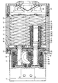
- the motor housing 2 rests on the foot part 1, with the flange-like base plate at the top 3 is optionally connected in one piece, on which the scoop chamber 4 is built. This is closed at the top by a cover 5 which contains a suction opening 6.
- the flange plates 50 of the bearing body in a manner to be explained later 7 attached, each serving to support a rotor 8, the circumference of which is preferred two-helically arranged displacer projections 9 carries in the type of tooth engagement in the conveying cavities 10 between the displacer projections 9 of the adjacent rotor.
- the displacement projections also have an effect 9 together on the circumference with the inner surface of the scoop housing part 4.
- the Rotors 8 are connected to the suction chamber 11 at the top and to the pressure chamber 12 at the bottom.
- the pressure chamber 12 is connected to a pressure outlet, not shown. These parts are provided at the lower end of the vertical scoop chamber.
- Each rotor 8 is non-rotatably connected to a shaft 20 which passes through the bottom of the bearing body 7 a permanently lubricated roller bearing 21 is mounted.
- a second, also permanently lubricated Rolling bearing 22 is located at the upper end of a tubular part 23 of the Bearing body 7, in a downward, ie pressure side, open, concentric bore 24 of the rotor 8 protrudes.
- This bearing 22 is preferably located above the Center of the rotor 8.
- the tubular part 23 of the bearing body preferably extends by the greater part of the length of the rotor 8.
- the end of the tubular part 23 is in a vertical arrangement of the pump much higher than the pressure outlet 17. This is helpful for protecting the bearing and drive region from the ingress of liquid or other heavy impurities from the scooping area.
- Cooling channels 25 are provided in the tubular part 23 of the bearing body. the across channels 26 with a cooling water source and via corresponding channels shown in the drawing non-appearance. connected to a cooling water drain.
- the cooling channels 25 are preferably formed by helical recesses through a sleeve are tightly covered.
- the cooling of the rotor bearings extends the service life or the Maintenance intervals of these bearings if they are permanently lubricated with grease.
- the peripheral surface of the tubular part 23 of the bearing body kept at low temperature. This peripheral surface is the inner peripheral surface of the cavity 24 of the rotor with a small distance opposite.
- these areas are like this trained that they are capable of good heat exchange and thus heat from the Rotor indirectly via the tubular part 23 of the bearing body and its cooling devices 25 can be dissipated.
- these can be configured in a suitable manner. For example they can be treated or burnished so that the radiation exchange is favored by high absorption coefficients.
- An area or both can be used for this purpose be rough or with heat exchange fins or threads or the like.
- Suitable sealing and / or locking devices are provided.
- the equipment of the opposing surfaces of the bearing body is advantageous 23 and the inner surfaces of the rotor cavity 24 on one side or on both Sides with a feed thread, not shown, that have a feed effect from the rotor cavity 24 exercises towards the pressure chamber 12.
- This promotional effect works because of it higher density primarily on solid or liquid particles and thereby prevents their penetration into the bearing and drive area.
- the conveyor thread is expedient designed so that this effect even at significantly reduced speed is effective.
- the promotional effect can also be brought about by this. That the gap between the rotor and bearing body widens conically towards the pressure chamber.
- the gap width (distance of the Surface of the bearing body from the surface of the rotor) remains essentially constant.
- the surfaces facing each other can also be used in this case be provided with a conveyor thread on one or both sides; required but it is not.
- the cleaning operation is not carried out continuously. but periodically when cleaning is required (e.g. due to an increase in drive torque) is detected. Thanks to the pump's insensitivity to liquids relatively large amounts of liquid can then also be used. If the operating speed due to the amount or type of cleaning fluid used cannot be held. the speed can be reduced accordingly.
- the speed can be dependent controlled by the drive torque, which with increased power requirements automatically to a corresponding reduction in speed compared to the operating speed leads.
- the continuous rotation of the rotors even during the cleaning phase not only serves to seal the rotor bearing, but also promotes the action the cleaning liquid on the soiled surfaces.
- the promotional effect in the gap between the rotor and bearing body can also be used to promote Seal gas can be used independently of an external compressed gas source. In general but is the effect of such a pressurized gas source to promote the sealing gas prefer to be independent of the rotor speed in the sealing gas supply.
- the scoop chamber 4 can contain a chamber 30, the whole or over a Much of the circumference rotates and circulates through the cooling water to the housing to keep at a predetermined temperature. Cooling of the housing jacket is not in required in all cases. However, it is advantageous in the context of the invention possible because the rotors 8 are cooled and therefore their thermal expansion is limited. There is no need to fear that the rotors are only due to this Housing start up because it is stretching while the housing is at a lower temperature is held.
- the pump according to the invention can be equipped with pre-inlet. It means that Channels 31 in the areas of high, possibly even medium compression in the housing are provided. due to the gas in the pumping chamber of higher pressure than the compression stage corresponds to this area of the scooping space, is let in to effect cooling and / or noise reduction according to known principles.
- the pre-inlet gas can be directly the Pressure side of the pump can be removed by placing it in the cooler pockets 30 of the scoop jacket 4 is cooled. For this purpose, it can be passed through heat exchanger tubes 32 become.
- roller bearings 21, 22 in the example shown are angular contact ball bearings, which are set against each other by a spring 29.
- Each shaft 20 carries below the Bearing 21 preferably immediately. i.e. without an intermediate clutch, the rotor 35 of the drive motor, the stator 36 is arranged in the motor housing 2.
- the Motor housing can be equipped with cooling channels 38.
- the flange plates 50 which in the example shown with the bearing bodies 7 from one Pieces are made with their outer edges 51, which are essentially the circumference follow the scoop chamber 4, and their abutting inner edges 52 the top of the base plate 3 placed.
- the flange plates 50 are opposite Base plate 3 sealed. Also the end faces following a secant in radial section 53, on which they lie against each other, are equipped with a sealing insert.
- a recess is provided under the flange plates 50, between the edges 51, 52, which includes a space 39 with the top of the base plate 3, which is for receiving of synchronization gears 40, which rotates with known means on the Shafts 20 are arranged between the bearings 21 and the motor rotors. So that they Can comb the area of the inner edges 52 of the flange plates 50 together. point the inner edges at a corresponding point on a cutout through which the gears reach through. Below this section there is a bridge on each side 1 the reference line of the reference number 52, which generally designates the inner edge points.
- This web is not only advantageous for reasons of stability, but also because it is a circumferential seal on the one hand against the base plate 3 and on the other hand allows between the flattened secant surfaces of the flange plates 50.
- the recesses 39 in the flange plates 50 have a diameter that is larger than the diameter of the synchronization gears 40. They are in relation to the Inner edges 52 arranged a little eccentrically so that the synchronization gears 40 when assembling the rotor assemblies despite the presence of the sealing web can be used at 52.
- the synchronization gears 40 can also serve as pulse generator disks or be supplemented by additional pulse generator disks. that are sensed by sensors 42 1, one of which is shown in FIG. These sensors 42 are with a control device in connection, which the respective rotational position of the rotors relative to one Setpoint is monitored and corrected via the drive. It is a synchronization of the rotors electronically, which is known as such and therefore no further explanation is required here.
- the game between the teeth of the synchronization gears 40 is slightly less than the backlash between the projections 9 of the rotors 8. However, it is larger than the synchronization tolerance of the electronic ones Synchronization device.
- the performance data of the pump are determined by the drive power and speed by the displacement or delivery volume formed on the rotors and thus by the Length of the rotors determined.
- the funding data can therefore be changed in that the length of the pump part containing the rotors is changed.
- a range of Pumps with different performance data are therefore characterized by this from that the individual pumps of this series differ by grading the length distinguish between these parts, the scoop chamber, the rotors and possibly the tubular. parts of the bearing bodies protruding into the rotors.
- each rotor with the associated bearing and drive devices forms an independently mountable unit which, in addition to the rotor, consists of the bearings 21, 22, the bearing body 7, the cooling devices provided therein, the shaft 20, the synchronization gear 40, the associated sensor 42 and the motor rotor 35.
- These units are completely pre-assembled in the pump. You can go after the removal of the scoop chamber easily removed from the base plate 3 or be used. Your replacement can therefore be left to the user. while the manufacturer takes care of the maintenance of the sensitive units as such.
- the pump is preferably of an isochoric design to handle larger quantities of liquid to be able to support without harm.
Landscapes
- Engineering & Computer Science (AREA)
- Mechanical Engineering (AREA)
- General Engineering & Computer Science (AREA)
- Applications Or Details Of Rotary Compressors (AREA)
- Structures Of Non-Positive Displacement Pumps (AREA)
- Rotary Pumps (AREA)
Description
Claims (14)
- Mehrstufiger Schraubenspindelverdichter, dessen Verdrängerrotoren (8) druckseitig fliegend gelagert sind an einem die Rotorwelle (20) und wenigstens ein rotorseitiges Lager (22) einschließenden, jeweils in den Rotor (8) hineinragenden, stationären Lagerrohr (23), dadurch gekennzeichnet, daß die Rotoren (8) druckseitig stärker als saugseitig gekühlt werden, indem der jeweils in einen Rotor hineinragende Teil des Lagerrohrs (23) gekühlt ist und die einander gegenüberstehenden Umfangsflächen des Rotors (8) und des Lagerrohrs (23) wärmeaustauschfähig zueinander angeordnet sind.
- Verdichter nach Anspruch 1, dadurch gekennzeichnet, daß der Zwischenraum zwischen den einander gegenüberstehenden Oberflächen des Rotors (8) und des Lagerrohrs (23) mit der Druckseite (12) in Verbindung steht.
- Verdichter nach Anspruch 1 oder 2, dadurch gekennzeichnet, daß wenigstens eine der genannten Umfangsflächen mit den Wärmeaustausch mit dem dazwischen befindlichen Medium verbessemden Erhöhungen und Vertiefungen versehen sind.
- Verdichter nach einem der Ansprüche 1 bis 3, dadurch gekennzeichnet, daß die genannten Umfangsflächen mit einer hohen Absorptionszahl für Wärmestrahlung ausgestattet sind.
- Verdichter nach einem der Ansprüche 1 bis 4, dadurch gekennzeichnet, daß mindestens der in den Rotor (8) hineinragende Teil des Lagerrohrs (23) von Kühlflüssigkeit durchströmte Kanäle (25) enthält.
- Verdichter nach Anspruch 5, dadurch gekennzeichnet, daß die Kühlkanäle (25) nahe der dem Rotor (8) gegenüberliegenden Umfangsfläche des Lagerrohrs (23) angeordnet sind.
- Verdichter nach einem der Ansprüche 1 bis 6, dadurch gekennzeichnet, daß die einander mit geringem Spiel gegenüberstehenden Umfangsflächen des Rotors (8) und des Lagerrohrs ( 23) als berührungsfrei zusammenwirkende Förderorgane mit aus dem Rotor (8) hinausführender Förderrichtung ausgebildet sind.
- Verdichter nach Anspruch 7, dadurch gekennzeichnet. daß er im wesentlichen vertikal mit geodätisch tief gelegener Auslaßöffnung angeordnet ist.
- Verdichter nach Anspruch 7, dadurch gekennzeichnet, daß wenigstens eine der beiden einander gegenüberstehenden Umfangsflächen mit einem Fördergewinde (28) versehen ist.
- Verdichter nach Anspruch 7, dadurch gekennzeichnet, daß die einander gegenüberstehenden Umfangsflächen konisch mit einem in Förderrichtung sich vergrößernden Durchmesser ausgebildet sind.
- Verdichter nach einem der Ansprüche 1 bis 10, dadurch gekennzeichnet. daß der Rotorhohlraum (24) mit einer Sperrgasquelle verbunden ist.
- Verdichter nach einem der Ansprüche 7 bis 11, dadurch gekennzeichnet, daß Einrichtungen zum drehmomentabhängigen Steuern/Regeln des Rotorantriebs vorgesehen sind.
- Verdichter nach Anspruch 12, dadurch gekennzeichnet, daß Einrichtungen (27) zum Einlaß einer Waschflüssigkeit in den Schöpfraum vorgesehen sind.
- Verfahren zum Reinigen eines Verdichters nach einem der Ansprüche 1 bis 13, dadurch gekennzeichnet, daß Waschflüssigkeit in den Schöpfraum gegeben und die Rotoren drehmomentabhängig angetrieben werden.
Applications Claiming Priority (5)
| Application Number | Priority Date | Filing Date | Title |
|---|---|---|---|
| DE1995122557 DE19522557A1 (de) | 1995-06-21 | 1995-06-21 | Drehkolbenverdichter, insbesondere Vakuumpumpe |
| DE19522557 | 1995-06-21 | ||
| DE1995122559 DE19522559A1 (de) | 1995-06-21 | 1995-06-21 | Verdichter mit axialer Förderrichtung, insbesondere in Schraubenspindel-Bauweise |
| DE19522559 | 1995-06-21 | ||
| PCT/EP1996/002631 WO1997001038A1 (de) | 1995-06-21 | 1996-06-18 | Mehrstufiger schraubenspindelverdichter |
Publications (3)
| Publication Number | Publication Date |
|---|---|
| EP0834018A1 EP0834018A1 (de) | 1998-04-08 |
| EP0834018B1 true EP0834018B1 (de) | 1999-12-08 |
| EP0834018B2 EP0834018B2 (de) | 2006-10-25 |
Family
ID=26016151
Family Applications (1)
| Application Number | Title | Priority Date | Filing Date |
|---|---|---|---|
| EP96922831A Expired - Lifetime EP0834018B2 (de) | 1995-06-21 | 1996-06-18 | Verfahren zum Kühlen eines mehrstufigen Schraubenspindelverdichters |
Country Status (12)
| Country | Link |
|---|---|
| US (1) | US5924855A (de) |
| EP (1) | EP0834018B2 (de) |
| JP (1) | JP3965507B2 (de) |
| KR (1) | KR100424386B1 (de) |
| AT (1) | ATE187528T1 (de) |
| DE (1) | DE59603870D1 (de) |
| DK (1) | DK0834018T4 (de) |
| ES (1) | ES2141515T5 (de) |
| GR (1) | GR3032683T3 (de) |
| PT (1) | PT834018E (de) |
| TW (1) | TW377384B (de) |
| WO (1) | WO1997001038A1 (de) |
Families Citing this family (27)
| Publication number | Priority date | Publication date | Assignee | Title |
|---|---|---|---|---|
| DE19724643A1 (de) * | 1997-06-11 | 1998-12-17 | Sihi Gmbh & Co Kg | Schraubenverdichter und Verfahren zum Betrieb desselben |
| DE19745616A1 (de) | 1997-10-10 | 1999-04-15 | Leybold Vakuum Gmbh | Gekühlte Schraubenvakuumpumpe |
| DE19800825A1 (de) * | 1998-01-02 | 1999-07-08 | Schacht Friedrich | Trockenverdichtende Schraubenspindelpumpe |
| US6045343A (en) * | 1998-01-15 | 2000-04-04 | Sunny King Machinery Co., Ltd. | Internally cooling rotary compression equipment |
| DE19926891C2 (de) * | 1999-06-12 | 2002-06-13 | Diro Konstruktions Gmbh & Co K | Verfahren zum Betreiben einer Turbomaschine und Turbomaschine |
| GB9913969D0 (en) * | 1999-06-16 | 1999-08-18 | Boc Group Plc | Improvements in screw pumps |
| DE19963171A1 (de) * | 1999-12-27 | 2001-06-28 | Leybold Vakuum Gmbh | Gekühlte Schraubenvakuumpumpe |
| DE19963172A1 (de) | 1999-12-27 | 2001-06-28 | Leybold Vakuum Gmbh | Schraubenpumpe mit einem Kühlmittelkreislauf |
| US6394777B2 (en) | 2000-01-07 | 2002-05-28 | The Nash Engineering Company | Cooling gas in a rotary screw type pump |
| DE10039006A1 (de) * | 2000-08-10 | 2002-02-21 | Leybold Vakuum Gmbh | Zweiwellenvakuumpumpe |
| GB2370320A (en) * | 2000-12-21 | 2002-06-26 | Ingersoll Rand Europ Sales Ltd | Compressor and driving motor assembly |
| WO2002065366A1 (en) * | 2001-02-13 | 2002-08-22 | Yonet.Co., Ltd. | Method and system for ticket purchasing and issuing using ic card |
| JP4403670B2 (ja) * | 2001-05-16 | 2010-01-27 | 株式会社デンソー | コンプレッサ |
| GB0223767D0 (en) * | 2002-10-14 | 2002-11-20 | Boc Group Plc | Pump cleaning |
| AU2003269250A1 (en) * | 2002-10-14 | 2004-05-04 | The Boc Group Plc | Rotary piston vacuum pump with washing installation |
| DE20302989U1 (de) * | 2003-02-24 | 2004-07-08 | Werner Rietschle Gmbh + Co. Kg | Drehkolbenpumpe |
| JP4558349B2 (ja) * | 2004-03-02 | 2010-10-06 | 財団法人国際科学振興財団 | 真空ポンプ |
| EP1784576B2 (de) * | 2004-09-02 | 2016-01-13 | Edwards Limited | Kühlen von pumprotoren |
| JP2007170341A (ja) * | 2005-12-26 | 2007-07-05 | Toyota Industries Corp | スクリュー式流体機械 |
| US8007264B2 (en) * | 2006-08-08 | 2011-08-30 | Spx Corporation | Positive displacement pump apparatus and method |
| US20080121497A1 (en) * | 2006-11-27 | 2008-05-29 | Christopher Esterson | Heated/cool screw conveyor |
| EP2233748B1 (de) * | 2009-03-10 | 2017-05-24 | Grundfos Management A/S | Mehrstufige Kreiselpumpe |
| CN102410219A (zh) * | 2011-11-24 | 2012-04-11 | 威海智德真空科技有限公司 | 一种立式干式螺杆真空泵 |
| EP3568572A1 (de) * | 2017-01-11 | 2019-11-20 | Carrier Corporation | Strömungsmaschine mit schraubenförmigen gelappten rotoren |
| CN212086044U (zh) * | 2017-03-21 | 2020-12-04 | 创科(澳门离岸商业服务)有限公司 | 无刷电动机 |
| CN113544384B (zh) * | 2019-03-14 | 2023-09-08 | 阿特利耶博世股份有限公司 | 干式气体泵和多个干式气体泵的组 |
| DE102020103384B4 (de) | 2020-02-11 | 2025-11-13 | Gardner Denver Deutschland Gmbh | Schraubenverdichter mit einseitig gelagerten Rotoren |
Citations (3)
| Publication number | Priority date | Publication date | Assignee | Title |
|---|---|---|---|---|
| EP0290662A1 (de) * | 1987-05-15 | 1988-11-17 | Leybold Aktiengesellschaft | Zweiwellenvakuumpumpe mit Schöpfraum |
| EP0472933A2 (de) * | 1990-08-01 | 1992-03-04 | Matsushita Electric Industrial Co., Ltd. | Drehanlage für flüssige Medien |
| EP0585911A1 (de) * | 1992-09-03 | 1994-03-09 | Matsushita Electric Industrial Co., Ltd. | Zweistufige Trockenprimärpumpe |
Family Cites Families (7)
| Publication number | Priority date | Publication date | Assignee | Title |
|---|---|---|---|---|
| US3289600A (en) * | 1964-03-13 | 1966-12-06 | Joseph E Whitfield | Helically threaded rotors for screw type pumps, compressors and similar devices |
| US3795117A (en) * | 1972-09-01 | 1974-03-05 | Dunham Bush Inc | Injection cooling of screw compressors |
| DE2544082A1 (de) * | 1975-10-02 | 1977-04-14 | Comprotek Sa | Drehkolbenmaschine |
| US4515540A (en) * | 1983-11-22 | 1985-05-07 | Frick Company | Variable liquid refrigerant injection port locator for screw compressor equipped with automatic variable volume ratio |
| EP0290664B1 (de) * | 1987-05-15 | 1991-12-27 | Leybold Aktiengesellschaft | Zweiwellenpumpe |
| JP3074829B2 (ja) * | 1991-09-05 | 2000-08-07 | 松下電器産業株式会社 | 流体回転装置 |
| US5269667A (en) * | 1993-02-24 | 1993-12-14 | Ingersoll-Rand Company | Removabe discharge port plate for a compressor |
-
1996
- 1996-06-18 US US08/981,322 patent/US5924855A/en not_active Expired - Fee Related
- 1996-06-18 PT PT96922831T patent/PT834018E/pt unknown
- 1996-06-18 EP EP96922831A patent/EP0834018B2/de not_active Expired - Lifetime
- 1996-06-18 KR KR1019970709576A patent/KR100424386B1/ko not_active Expired - Fee Related
- 1996-06-18 JP JP50357097A patent/JP3965507B2/ja not_active Expired - Fee Related
- 1996-06-18 AT AT96922831T patent/ATE187528T1/de not_active IP Right Cessation
- 1996-06-18 WO PCT/EP1996/002631 patent/WO1997001038A1/de not_active Ceased
- 1996-06-18 DE DE59603870T patent/DE59603870D1/de not_active Expired - Lifetime
- 1996-06-18 ES ES96922831T patent/ES2141515T5/es not_active Expired - Lifetime
- 1996-06-18 DK DK96922831T patent/DK0834018T4/da active
- 1996-06-19 TW TW085107398A patent/TW377384B/zh not_active IP Right Cessation
-
2000
- 2000-02-16 GR GR20000400381T patent/GR3032683T3/el unknown
Patent Citations (3)
| Publication number | Priority date | Publication date | Assignee | Title |
|---|---|---|---|---|
| EP0290662A1 (de) * | 1987-05-15 | 1988-11-17 | Leybold Aktiengesellschaft | Zweiwellenvakuumpumpe mit Schöpfraum |
| EP0472933A2 (de) * | 1990-08-01 | 1992-03-04 | Matsushita Electric Industrial Co., Ltd. | Drehanlage für flüssige Medien |
| EP0585911A1 (de) * | 1992-09-03 | 1994-03-09 | Matsushita Electric Industrial Co., Ltd. | Zweistufige Trockenprimärpumpe |
Also Published As
| Publication number | Publication date |
|---|---|
| WO1997001038A1 (de) | 1997-01-09 |
| ES2141515T3 (es) | 2000-03-16 |
| GR3032683T3 (en) | 2000-06-30 |
| EP0834018A1 (de) | 1998-04-08 |
| ATE187528T1 (de) | 1999-12-15 |
| DK0834018T3 (da) | 2000-06-13 |
| KR20000000512A (ko) | 2000-01-15 |
| DE59603870D1 (de) | 2000-01-13 |
| EP0834018B2 (de) | 2006-10-25 |
| KR100424386B1 (ko) | 2004-07-15 |
| PT834018E (pt) | 2000-05-31 |
| JPH11508015A (ja) | 1999-07-13 |
| DK0834018T4 (da) | 2007-02-26 |
| US5924855A (en) | 1999-07-20 |
| TW377384B (en) | 1999-12-21 |
| ES2141515T5 (es) | 2007-06-16 |
| JP3965507B2 (ja) | 2007-08-29 |
Similar Documents
| Publication | Publication Date | Title |
|---|---|---|
| EP0834018B2 (de) | Verfahren zum Kühlen eines mehrstufigen Schraubenspindelverdichters | |
| EP0834017B1 (de) | Vakuumpumpe | |
| DE69207722T2 (de) | Elektromotorisch angetriebene Hydrovorrichtung, mit integrierter Pumpe | |
| EP1021653B1 (de) | Gekühlte schraubenvakuumpumpe | |
| DE2240018C3 (de) | Ein- oder mehrstufiger Flügelzellen- oder Schraubenkolbenverdichter | |
| EP1163452B1 (de) | Schraubenkompressor | |
| DE19522559A1 (de) | Verdichter mit axialer Förderrichtung, insbesondere in Schraubenspindel-Bauweise | |
| EP1163451B1 (de) | Schraubenkompressor | |
| DE3619754C2 (de) | ||
| DE19963172A1 (de) | Schraubenpumpe mit einem Kühlmittelkreislauf | |
| DE3347509C2 (de) | ||
| WO2001048383A1 (de) | Gekühlte schraubenvakuumpumpe | |
| WO2000012900A1 (de) | Trockenverdichtende schraubenspindelpumpe | |
| DE19745615A1 (de) | Schraubenvakuumpumpe mit Rotoren | |
| EP0290663B1 (de) | Ein- oder mehrstufige Zweiwellenvakuumpumpe | |
| DE1933287A1 (de) | Rotationsmaschine | |
| DE19522560A1 (de) | Vakuumpumpe mit einem Paar innerhalb eines axial durchströmten Schöpfraums umlaufender Verdrängerrotoren | |
| DE10051131A1 (de) | Schmierungsstruktur für eine Brennkraftmaschine | |
| DE20302989U1 (de) | Drehkolbenpumpe | |
| DE1600651A1 (de) | Wellendichtung | |
| EP0617201B1 (de) | Füll-, Fluid-Transport- und Pumpeinrichtung | |
| DE19748385A1 (de) | Trockenlaufender Schraubenverdichter oder Vakuumpumpe | |
| DE19522557A1 (de) | Drehkolbenverdichter, insbesondere Vakuumpumpe | |
| DE3132076A1 (de) | "selbsttaetig einrueckbare zahnkupplung" | |
| DE10149366A1 (de) | Axial fördernde Reibungsvakuumpumpe |
Legal Events
| Date | Code | Title | Description |
|---|---|---|---|
| PUAI | Public reference made under article 153(3) epc to a published international application that has entered the european phase |
Free format text: ORIGINAL CODE: 0009012 |
|
| 17P | Request for examination filed |
Effective date: 19971112 |
|
| AK | Designated contracting states |
Kind code of ref document: A1 Designated state(s): AT BE CH DE DK ES FI FR GB GR IE IT LI LU NL PT SE |
|
| GRAG | Despatch of communication of intention to grant |
Free format text: ORIGINAL CODE: EPIDOS AGRA |
|
| 17Q | First examination report despatched |
Effective date: 19990219 |
|
| GRAG | Despatch of communication of intention to grant |
Free format text: ORIGINAL CODE: EPIDOS AGRA |
|
| GRAH | Despatch of communication of intention to grant a patent |
Free format text: ORIGINAL CODE: EPIDOS IGRA |
|
| RAP1 | Party data changed (applicant data changed or rights of an application transferred) |
Owner name: STERLING INDUSTRY CONSULT GMBH |
|
| GRAH | Despatch of communication of intention to grant a patent |
Free format text: ORIGINAL CODE: EPIDOS IGRA |
|
| GRAA | (expected) grant |
Free format text: ORIGINAL CODE: 0009210 |
|
| AK | Designated contracting states |
Kind code of ref document: B1 Designated state(s): AT BE CH DE DK ES FI FR GB GR IE IT LI LU NL PT SE |
|
| REF | Corresponds to: |
Ref document number: 187528 Country of ref document: AT Date of ref document: 19991215 Kind code of ref document: T |
|
| REG | Reference to a national code |
Ref country code: CH Ref legal event code: EP |
|
| REF | Corresponds to: |
Ref document number: 59603870 Country of ref document: DE Date of ref document: 20000113 |
|
| REG | Reference to a national code |
Ref country code: CH Ref legal event code: NV Representative=s name: TROESCH SCHEIDEGGER WERNER AG |
|
| REG | Reference to a national code |
Ref country code: IE Ref legal event code: FG4D |
|
| ET | Fr: translation filed | ||
| ITF | It: translation for a ep patent filed | ||
| GBT | Gb: translation of ep patent filed (gb section 77(6)(a)/1977) |
Effective date: 20000222 |
|
| REG | Reference to a national code |
Ref country code: ES Ref legal event code: FG2A Ref document number: 2141515 Country of ref document: ES Kind code of ref document: T3 |
|
| REG | Reference to a national code |
Ref country code: PT Ref legal event code: SC4A Free format text: AVAILABILITY OF NATIONAL TRANSLATION Effective date: 20000306 |
|
| REG | Reference to a national code |
Ref country code: DK Ref legal event code: T3 |
|
| PLBE | No opposition filed within time limit |
Free format text: ORIGINAL CODE: 0009261 |
|
| PLBQ | Unpublished change to opponent data |
Free format text: ORIGINAL CODE: EPIDOS OPPO |
|
| PLAA | Information modified related to event that no opposition was filed |
Free format text: ORIGINAL CODE: 0009299DELT |
|
| PLBI | Opposition filed |
Free format text: ORIGINAL CODE: 0009260 |
|
| 26N | No opposition filed | ||
| PLBF | Reply of patent proprietor to notice(s) of opposition |
Free format text: ORIGINAL CODE: EPIDOS OBSO |
|
| 26 | Opposition filed |
Opponent name: LEYBOLD VAKUUM GMBH Effective date: 20000823 |
|
| D26N | No opposition filed (deleted) | ||
| PLBF | Reply of patent proprietor to notice(s) of opposition |
Free format text: ORIGINAL CODE: EPIDOS OBSO |
|
| NLR1 | Nl: opposition has been filed with the epo |
Opponent name: LEYBOLD VAKUUM GMBH |
|
| DX | Miscellaneous (deleted) | ||
| REG | Reference to a national code |
Ref country code: GB Ref legal event code: IF02 |
|
| RTI2 | Title (correction) |
Free format text: METHOD FOR COOLING A MULTISTAGE SCREW-SPINDLE COMPRESSOR |
|
| RTI2 | Title (correction) |
Free format text: METHOD FOR COOLING A MULTISTAGE SCREW-SPINDLE COMPRESSOR |
|
| RTI2 | Title (correction) |
Free format text: METHOD FOR COOLING A MULTISTAGE SCREW-SPINDLE COMPRESSOR |
|
| APBP | Date of receipt of notice of appeal recorded |
Free format text: ORIGINAL CODE: EPIDOSNNOA2O |
|
| APBQ | Date of receipt of statement of grounds of appeal recorded |
Free format text: ORIGINAL CODE: EPIDOSNNOA3O |
|
| APAA | Appeal reference recorded |
Free format text: ORIGINAL CODE: EPIDOS REFN |
|
| APAH | Appeal reference modified |
Free format text: ORIGINAL CODE: EPIDOSCREFNO |
|
| APBU | Appeal procedure closed |
Free format text: ORIGINAL CODE: EPIDOSNNOA9O |
|
| PUAH | Patent maintained in amended form |
Free format text: ORIGINAL CODE: 0009272 |
|
| STAA | Information on the status of an ep patent application or granted ep patent |
Free format text: STATUS: PATENT MAINTAINED AS AMENDED |
|
| 27A | Patent maintained in amended form |
Effective date: 20061025 |
|
| AK | Designated contracting states |
Kind code of ref document: B2 Designated state(s): AT BE CH DE DK ES FI FR GB GR IE IT LI LU NL PT SE |
|
| REG | Reference to a national code |
Ref country code: CH Ref legal event code: AEN Free format text: AUFRECHTERHALTUNG DES PATENTES IN GEAENDERTER FORM |
|
| REG | Reference to a national code |
Ref country code: SE Ref legal event code: RPEO |
|
| NLR2 | Nl: decision of opposition |
Effective date: 20061025 |
|
| GBTA | Gb: translation of amended ep patent filed (gb section 77(6)(b)/1977) | ||
| REG | Reference to a national code |
Ref country code: GR Ref legal event code: EP Ref document number: 20070400206 Country of ref document: GR |
|
| REG | Reference to a national code |
Ref country code: DK Ref legal event code: T4 |
|
| NLR3 | Nl: receipt of modified translations in the netherlands language after an opposition procedure | ||
| ET3 | Fr: translation filed ** decision concerning opposition | ||
| REG | Reference to a national code |
Ref country code: ES Ref legal event code: DC2A Date of ref document: 20070125 Kind code of ref document: T5 |
|
| PGFP | Annual fee paid to national office [announced via postgrant information from national office to epo] |
Ref country code: NL Payment date: 20090624 Year of fee payment: 14 Ref country code: IE Payment date: 20090618 Year of fee payment: 14 Ref country code: ES Payment date: 20090629 Year of fee payment: 14 Ref country code: DK Payment date: 20090622 Year of fee payment: 14 |
|
| PGFP | Annual fee paid to national office [announced via postgrant information from national office to epo] |
Ref country code: SE Payment date: 20090623 Year of fee payment: 14 Ref country code: PT Payment date: 20090617 Year of fee payment: 14 Ref country code: LU Payment date: 20090625 Year of fee payment: 14 Ref country code: FI Payment date: 20090624 Year of fee payment: 14 Ref country code: AT Payment date: 20090622 Year of fee payment: 14 |
|
| PGFP | Annual fee paid to national office [announced via postgrant information from national office to epo] |
Ref country code: BE Payment date: 20090623 Year of fee payment: 14 |
|
| PGFP | Annual fee paid to national office [announced via postgrant information from national office to epo] |
Ref country code: FR Payment date: 20090618 Year of fee payment: 14 Ref country code: CH Payment date: 20090624 Year of fee payment: 14 |
|
| PGFP | Annual fee paid to national office [announced via postgrant information from national office to epo] |
Ref country code: GR Payment date: 20090629 Year of fee payment: 14 Ref country code: GB Payment date: 20090623 Year of fee payment: 14 |
|
| PGFP | Annual fee paid to national office [announced via postgrant information from national office to epo] |
Ref country code: IT Payment date: 20090626 Year of fee payment: 14 |
|
| REG | Reference to a national code |
Ref country code: PT Ref legal event code: MM4A Free format text: LAPSE DUE TO NON-PAYMENT OF FEES Effective date: 20101220 |
|
| BERE | Be: lapsed |
Owner name: *STERLING INDUSTRY CONSULT G.M.B.H. Effective date: 20100630 |
|
| REG | Reference to a national code |
Ref country code: NL Ref legal event code: V1 Effective date: 20110101 |
|
| PG25 | Lapsed in a contracting state [announced via postgrant information from national office to epo] |
Ref country code: FI Free format text: LAPSE BECAUSE OF NON-PAYMENT OF DUE FEES Effective date: 20100618 |
|
| REG | Reference to a national code |
Ref country code: CH Ref legal event code: PL Ref country code: DK Ref legal event code: EBP |
|
| EUG | Se: european patent has lapsed | ||
| GBPC | Gb: european patent ceased through non-payment of renewal fee |
Effective date: 20100618 |
|
| PG25 | Lapsed in a contracting state [announced via postgrant information from national office to epo] |
Ref country code: PT Free format text: LAPSE BECAUSE OF NON-PAYMENT OF DUE FEES Effective date: 20101220 |
|
| REG | Reference to a national code |
Ref country code: FR Ref legal event code: ST Effective date: 20110228 |
|
| REG | Reference to a national code |
Ref country code: IE Ref legal event code: MM4A |
|
| PG25 | Lapsed in a contracting state [announced via postgrant information from national office to epo] |
Ref country code: IT Free format text: LAPSE BECAUSE OF NON-PAYMENT OF DUE FEES Effective date: 20100618 |
|
| PG25 | Lapsed in a contracting state [announced via postgrant information from national office to epo] |
Ref country code: IE Free format text: LAPSE BECAUSE OF NON-PAYMENT OF DUE FEES Effective date: 20100618 Ref country code: CH Free format text: LAPSE BECAUSE OF NON-PAYMENT OF DUE FEES Effective date: 20100630 Ref country code: LI Free format text: LAPSE BECAUSE OF NON-PAYMENT OF DUE FEES Effective date: 20100630 |
|
| PG25 | Lapsed in a contracting state [announced via postgrant information from national office to epo] |
Ref country code: FR Free format text: LAPSE BECAUSE OF NON-PAYMENT OF DUE FEES Effective date: 20100630 Ref country code: AT Free format text: LAPSE BECAUSE OF NON-PAYMENT OF DUE FEES Effective date: 20100618 Ref country code: NL Free format text: LAPSE BECAUSE OF NON-PAYMENT OF DUE FEES Effective date: 20110101 |
|
| PG25 | Lapsed in a contracting state [announced via postgrant information from national office to epo] |
Ref country code: GR Free format text: LAPSE BECAUSE OF NON-PAYMENT OF DUE FEES Effective date: 20110104 Ref country code: BE Free format text: LAPSE BECAUSE OF NON-PAYMENT OF DUE FEES Effective date: 20100630 |
|
| REG | Reference to a national code |
Ref country code: ES Ref legal event code: FD2A Effective date: 20110718 |
|
| PG25 | Lapsed in a contracting state [announced via postgrant information from national office to epo] |
Ref country code: GB Free format text: LAPSE BECAUSE OF NON-PAYMENT OF DUE FEES Effective date: 20100618 Ref country code: ES Free format text: LAPSE BECAUSE OF NON-PAYMENT OF DUE FEES Effective date: 20110706 |
|
| PG25 | Lapsed in a contracting state [announced via postgrant information from national office to epo] |
Ref country code: DK Free format text: LAPSE BECAUSE OF NON-PAYMENT OF DUE FEES Effective date: 20100630 |
|
| PG25 | Lapsed in a contracting state [announced via postgrant information from national office to epo] |
Ref country code: ES Free format text: LAPSE BECAUSE OF NON-PAYMENT OF DUE FEES Effective date: 20100619 |
|
| PG25 | Lapsed in a contracting state [announced via postgrant information from national office to epo] |
Ref country code: LU Free format text: LAPSE BECAUSE OF NON-PAYMENT OF DUE FEES Effective date: 20100618 Ref country code: SE Free format text: LAPSE BECAUSE OF NON-PAYMENT OF DUE FEES Effective date: 20100619 |
|
| PGFP | Annual fee paid to national office [announced via postgrant information from national office to epo] |
Ref country code: DE Payment date: 20150629 Year of fee payment: 20 |
|
| REG | Reference to a national code |
Ref country code: GR Ref legal event code: ML Ref document number: 20070400206 Country of ref document: GR Effective date: 20110104 |
|
| REG | Reference to a national code |
Ref country code: DE Ref legal event code: R071 Ref document number: 59603870 Country of ref document: DE |