EP0834358A2 - Dispositif et procédé pour charger une station d'usinage avec des différentes pièces en forme de plaques - Google Patents
Dispositif et procédé pour charger une station d'usinage avec des différentes pièces en forme de plaques Download PDFInfo
- Publication number
- EP0834358A2 EP0834358A2 EP97116700A EP97116700A EP0834358A2 EP 0834358 A2 EP0834358 A2 EP 0834358A2 EP 97116700 A EP97116700 A EP 97116700A EP 97116700 A EP97116700 A EP 97116700A EP 0834358 A2 EP0834358 A2 EP 0834358A2
- Authority
- EP
- European Patent Office
- Prior art keywords
- stack
- transport device
- feed
- component
- components
- Prior art date
- Legal status (The legal status is an assumption and is not a legal conclusion. Google has not performed a legal analysis and makes no representation as to the accuracy of the status listed.)
- Withdrawn
Links
Images


Classifications
-
- B—PERFORMING OPERATIONS; TRANSPORTING
- B21—MECHANICAL METAL-WORKING WITHOUT ESSENTIALLY REMOVING MATERIAL; PUNCHING METAL
- B21D—WORKING OR PROCESSING OF SHEET METAL OR METAL TUBES, RODS OR PROFILES WITHOUT ESSENTIALLY REMOVING MATERIAL; PUNCHING METAL
- B21D43/00—Feeding, positioning or storing devices combined with, or arranged in, or specially adapted for use in connection with, apparatus for working or processing sheet metal, metal tubes or metal profiles; Associations therewith of cutting devices
-
- B—PERFORMING OPERATIONS; TRANSPORTING
- B23—MACHINE TOOLS; METAL-WORKING NOT OTHERWISE PROVIDED FOR
- B23Q—DETAILS, COMPONENTS, OR ACCESSORIES FOR MACHINE TOOLS, e.g. ARRANGEMENTS FOR COPYING OR CONTROLLING; MACHINE TOOLS IN GENERAL CHARACTERISED BY THE CONSTRUCTION OF PARTICULAR DETAILS OR COMPONENTS; COMBINATIONS OR ASSOCIATIONS OF METAL-WORKING MACHINES, NOT DIRECTED TO A PARTICULAR RESULT
- B23Q7/00—Arrangements for handling work specially combined with or arranged in, or specially adapted for use in connection with, machine tools, e.g. for conveying, loading, positioning, discharging, sorting
- B23Q7/16—Loading work on to conveyors; Arranging work on conveyors, e.g. varying spacing between individual workpieces
Definitions
- the invention relates to a device for loading a processing station with different plate-shaped components, in particular from sheet metal to a forming press or the like can be removed individually from stacks and alternately by means of conveyors can be fed to a transport device.
- the invention is still on a process for loading a processing station with different, plate-shaped components directed, in particular from sheets to a forming press, wherein the different components of corresponding component stacks removed and alternately by means of a conveyor conveyor be abandoned.
- Blanks for front and rear fenders one processing station feed, especially one with multiple dies provided forming press, in the with a press stroke simultaneously two or more different parts from the supplied Sheet metal blanks are manufactured.
- the various sheet metal blanks are stacked on pallets taken from the side next to one leading to the forming press Transport device, in particular a belt conveyor, arranged are transferred to them by means of a feed device will.
- the stack or the latter load pallet to assign a lifting device with which Stack is increased by an amount each time a component is removed is the thickness of the previously removed component corresponds.
- the stroke for the lifting device then remains for each component is about the same.
- the object of the invention is an apparatus and a method of the type mentioned at the beginning, with which it is possible Components of different shape and / or dimensions in uniform To supply time intervals to a processing station, wherein no interruptions when changing to a new component stack when feeding the components of different component types to the processing station.
- the procedure is a destacking station for each component type on each side of the transport device as well its own, the unstacking station of a component type on both sides the feed device reaching the transport device is provided, with a first stack of each component type one side of the transport device is unstacked and the unstacked components of the transport device by means of the associated Feeder can be abandoned while corresponding second batch of the same component types on each other side of the transport device is already in the waiting position are aligned to the feed device, and wherein after unstacking the first stack, the second stack of each Component type are unstacked while at the locations of the first stack of new, third stack in their waiting position be brought to the respective feed device.
- each feeder consists essentially of at least a controllable overhead conveyor, especially one Magnetic belt conveyor exists.
- the overhead conveyors are across Transport direction of the transport device arranged above this and have at least one circulating conveyor belt, whose conveying direction can be easily switched.
- magnetic tape conveyors have become special Proven useful where on the inside of the conveyor belts switchable magnet units are arranged with their Help the sheets be pulled against the conveyor belt and on the desired one Place by switching off the magnetic effect on the Transport device can be dropped.
- vacuum conveyor belts or to use a vacuum belt conveyor in which the components sucked onto the conveyor belt and held on it.
- the feeding devices for the different types of components are expediently arranged at a distance from each other, the At least the width of the component stack or the pallets carrying it corresponds. That way there can be no collisions or obstructions of a pallet with one component type by one on the same side of the transport device in one Unstacking arranged pallet with components of the other Component types come regardless of the position in which first pallet is located relative to the associated feed device.
- the unstacking station must be kept constant on each side the transport device expediently at least one lifting device assigned.
- Each unstacking station preferably has here its own lifting device so that the stacks of each component type on each side of the transport device independently of each other are adjustable in height. As particularly easy and hydraulic lifting tables have proven to be reliable proven, although screw jacks can also be used.
- the device according to the invention can have displacement devices for the component stack or the pallets supporting it be provided transversely to the conveying direction of the feed devices.
- shifting devices conveniently on the lifting devices arranged displacement cylinders or the like, can Component stack exactly in the desired position relative to the respective one Feeder can be positioned.
- each destacking station is preferably a stack scanner assigned, for example one or more light barriers, when moving the pallet carrying the stack recognize the front edge of a stack and the shifting device or the travel drive of the lifting table from quickly can switch slowly or to stop.
- Each unstacking station is preferably stacked with a sheet metal spreading device provided, for example for ferromagnetic components with a sheet metal spreading magnet device with several Permanent magnetic adjustable across the direction of the sheet Sheet metal spreading magnet, mounted on a crossbar could be.
- a sheet metal spreading magnet device with several Permanent magnetic adjustable across the direction of the sheet Sheet metal spreading magnet, mounted on a crossbar could be.
- Such sheet metal spreading magnets are able spread the top sheet of a stack from it, thereby avoiding two or more sheets can be removed from a stack at the same time.
- the components can feed devices from the individual component stacks with the help of transfer devices, for example by means of vacuum holding units and / or magnetic holding units, which grasp the components on their surface and against put on the conveyor belt of the associated feeder.
- the feeding devices can each have at least two of one have common drive belt conveyors whose Distance from each other is adjustable. This arrangement enables adapting the device to components of different widths, by adjusting the distance between the two belt conveyors that they have the component to be transported along their front and Grasp the rear edge. To ensure quick adjustability here, the belt conveyors are expediently by means of a motor driven threaded spindles adjustable.
- the device can be in the area of the feed devices and / or the transport device with at least one double sheet control device be provided with the help of which it can be determined whether one or more feed devices inadmissible a so-called double sheet from the stack has taken over, i.e. two individual sheets that result from adhesion or the like. stick together and the subsequent forming press must not be fed. If such is found Double sheet through the double sheet control device can briefly reverse the conveying direction of the transport device be and that deposited on the transport device Double sheet ejected from the device onto a double sheet tray will.
- the transport device for the components preferably consists essentially from at least one belt conveyor with holding devices for the components.
- Such belt conveyors can be used for Ferromagnetic components are preferably magnetic tape conveyors against which the sheets are firmly held against with the help of magnetic units revolving conveyor belt are pulled and so during their Transportes maintain their position relative to the conveyor belt. It is also possible, the holding devices from vacuum units build with the help of the components against the conveyor belt be sucked in.
- a particularly advantageous embodiment of the invention arises when a stack of one component type is unstacked from one side next to the transport device, while at the same time a stack of the other component type from the on the opposite side next to the transport device becomes.
- two stacks are different Components on the transport device diagonally to each other opposite, a first feed device the components from the first stack on one side of the transport device conveys towards the center, while a second feed device oppositely promotes and the components of the other side of the transport device.
- the delivery direction is unstacked of a component package of the feeder switched, whereupon the at the other diagonally aligned stack at least partially be unstacked.
- the Proven method according to the invention if after the complete Unstacking a first stack on a first side of the Transport device to the second stack of all component types the opposite side of the transport device be unstacked.
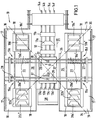
- 10 denotes a feeding device which serves to blank sheets 11a, 11b of different shapes and Alternating dimensions of a downstream processing station feed, in the present case a (not shown) Forming press, which is provided with two dies and at a press stroke from two different sheet metal blanks 11a, 11b the desired parts, for example body parts for a motor vehicle.
- a (not shown) Forming press which is provided with two dies and at a press stroke from two different sheet metal blanks 11a, 11b the desired parts, for example body parts for a motor vehicle.
- the sheet metal blanks 11a and 11b become the processing station fed by means of a transport device 12 which here in essentially from four parallel feed belts 13a-d and four behind them in the direction of transport Feed belts lying feed belts 14a-d, with whose help the sheet metal blanks are taken from the feed belts and be transported in the direction of the forming press.
- the feed belts 13a-d and the feed belts 14a-d have each a common, controllable drive, which, however, from For reasons of clarity, not shown in the drawings is.
- the approximately square loading device in plan view has a transfer station in each of its four corner areas 16 17 for pallets 18 on which the sheet metal part blanks 11a or 11b in three stacks 19a-c and 20a-c in the transport direction 21 of the transport device 12 are arranged one behind the other, wherein the inner stacks with 19a ', 20a', 19a '' and 20a '', the outer stacks with 19c ', 20c', 19c '' and 20c '' and the middle stacks with 19b ', 20b', 19b '' and 20b '' are.
- pallets 18 can thus the stack of sheet metal parts arranged thereon on both sides of the transport device 12 are arranged.
- the two pallets, the 1 on a common diagonal 34 are in Fig. 2 designated 18 ', while the two on the other Diagonal 35 arranged pallets are designated 18 ".
- the loading device 10 at all four corner areas with a lifting table 22 provided that an upper storage surface 23 for a pallet 18th forms the parallel there by means of a displacement device 24 is displaceable to the transport direction 21.
- the pallets are 18th with the various sheet metal blanks 11a and 11b in the device 10 arranged that pallets 18 'and 18' 'with the a component type 11a on both sides of the transport device 12 in Transport direction 21 at the rear and the pallets 18 'and 18' 'with Sheet metal blanks of the other component type 11b on both sides 25 or 26 of the transport device in the transport direction 21 at the front are in the loading device.
- Each component type 11a 11b is assigned its own feed device 27 or 28, each consisting essentially of a overhead conveyor, in the example shown a magnetic tape conveyor with two Conveyor belts 29 and a transfer device 30 each each unstacking station 15a-15d.
- the conveyor belts 29 both feed devices 27, 28 are reversible, i.e. your The direction of conveyance can be chosen freely and changed quickly.
- the distance a between the two feed devices 27 and 28 is approximately as large as the width b of a pallet.
- the different sheet blanks 11a and 11b are the Transport device 12 with the aid of the feed devices 27, 28 alternately abandoned, for which always diagonally opposite each other Stack 19a 'or 20a' unstacked at approximately the same time and with those running in opposite conveying directions 32 or 33 Conveyor belts 29 transported to the center of the plant and there be dropped onto the feed belts 13a-d.
- the transfer device 30 - here a vacuum cleaner - carries out a sheet from the respective stack to the conveyor belts 29 is always about the same.
- the device is not at standstill when loading the sheets to the subsequent processing station comes because after every complete unstacking of a stack there is already another on one side of the device Stack on hold on the other side of the device is located, from which the feed device after simple switching can remove sheets from their conveying direction.
- first two pallets 18 ′ lying opposite one another along the first diagonals 34 are completely de-stacked, and the pallets 18 ′′ aligned along the other diagonals 35 with their inner stacks 19a ′′ or 20a ′′ are only used for the time being as a stack of buffers, from which sheets are only removed in the time during which the already partially unloaded pallets 18 'move downward from the lifting tables along the first diagonal 34 and are repositioned under the feed conveyors.
- This has the consequence that only a few sheets are removed from the stacks 19a ′′ or 20a ′′ of the second pallets 18 ′′ when the first pallets 18 ′ are already completely empty and can be exchanged for new pallets.
- each stacking station one (only shown schematically)
- Stack scanner 26 assigned, each with two in Distance from each other light barriers when moving the pallets 18 by means of the displacement devices 24 scan the edges of the stack of sheets to be removed.
- the drive of the displacement device 24 is on quickly slowly switched and when palpated by the second light barrier shut down.
- the light barriers can be in their position can be adjusted by means of a driven threaded spindle.
- Double sheet i.e. two at the same time from a stack removed, adhering sheet metal blanks are fed, which results in serious damage to the press die
- the feeder 10 is on its feeders provided with double sheet control devices 37, which essentially consists of the thickness of the straight from the feeders transported components detected sensors consist. As soon as the sensors have an excessive (double) component thickness will determine the direction of transport of the feed belts 13a-d vice versa and those then dropped onto the feed belts Components to the rear from the device 10 on a double sheet metal shelf 38 ejected.
- the invention is not limited to that shown and described Embodiment limited, but there are many Changes and additions without going beyond the scope of the invention leave. So it is not absolutely necessary to use the different ones Components always from two different sides to feed the transport device at the same time, but it can also start with two stacks of different sheets from one side 25 are dismantled and then after switching the conveying direction the feeder the appropriate stacks of the second page 26. It is also particularly easy to do more Unstacking stations on both sides of the transport device be provided, for example, if three or more different Sheet metal blanks from the subsequent processing station should be fed alternately. In this case it is Feed direction of all pallets through the loading device expediently the same, which makes it possible to keep the distance to keep the feed devices apart from each other and on a measure to limit the width of each pallet approximately corresponds.
Landscapes
- Engineering & Computer Science (AREA)
- Mechanical Engineering (AREA)
- Sheets, Magazines, And Separation Thereof (AREA)
- Separation, Sorting, Adjustment, Or Bending Of Sheets To Be Conveyed (AREA)
Applications Claiming Priority (2)
| Application Number | Priority Date | Filing Date | Title |
|---|---|---|---|
| DE1996140517 DE19640517A1 (de) | 1996-10-01 | 1996-10-01 | Vorrichtung und Verfahren zum Beschicken einer Bearbeitungsstation mit unterschiedlichen plattenförmigen Bauteilen |
| DE19640517 | 1996-10-01 |
Publications (2)
| Publication Number | Publication Date |
|---|---|
| EP0834358A2 true EP0834358A2 (fr) | 1998-04-08 |
| EP0834358A3 EP0834358A3 (fr) | 1998-11-04 |
Family
ID=7807589
Family Applications (1)
| Application Number | Title | Priority Date | Filing Date |
|---|---|---|---|
| EP97116700A Withdrawn EP0834358A3 (fr) | 1996-10-01 | 1997-09-24 | Dispositif et procédé pour charger une station d'usinage avec des différentes pièces en forme de plaques |
Country Status (2)
| Country | Link |
|---|---|
| EP (1) | EP0834358A3 (fr) |
| DE (1) | DE19640517A1 (fr) |
Cited By (1)
| Publication number | Priority date | Publication date | Assignee | Title |
|---|---|---|---|---|
| EP4538812A1 (fr) * | 2023-10-09 | 2025-04-16 | Messer Cutting Systems GmbH | Procédé de transfert de plaques métalliques sur la table d'usinage d'une machine de traitement thermique et système de tri approprié à cet effet |
Families Citing this family (1)
| Publication number | Priority date | Publication date | Assignee | Title |
|---|---|---|---|---|
| CH696486A5 (de) * | 2002-04-18 | 2007-07-13 | Can Man Ruedi Umricht | Vorrichtung zum Abstapeln und Runden von Blechzuschnitten. |
Family Cites Families (3)
| Publication number | Priority date | Publication date | Assignee | Title |
|---|---|---|---|---|
| DE2131238C3 (de) * | 1971-06-24 | 1975-09-25 | L. Schuler Gmbh, 7320 Goeppingen | Verfahren zum kontinuierlichen und lückenlosen Vorschieben von Werkstoff-Streifen und Vorrichtung zur Durchführung des Verfahrens |
| FR2609428B1 (fr) * | 1987-01-14 | 1991-01-11 | Peugeot | Dispositif d'alimentation d'une presse a partir de deux piles de flans de tole |
| DE4225248A1 (de) * | 1992-07-31 | 1994-02-03 | Erfurt Umformtechnik Gmbh | Platinenzuführeinrichtung für eine Presse |
-
1996
- 1996-10-01 DE DE1996140517 patent/DE19640517A1/de not_active Withdrawn
-
1997
- 1997-09-24 EP EP97116700A patent/EP0834358A3/fr not_active Withdrawn
Cited By (2)
| Publication number | Priority date | Publication date | Assignee | Title |
|---|---|---|---|---|
| EP4538812A1 (fr) * | 2023-10-09 | 2025-04-16 | Messer Cutting Systems GmbH | Procédé de transfert de plaques métalliques sur la table d'usinage d'une machine de traitement thermique et système de tri approprié à cet effet |
| WO2025078422A1 (fr) * | 2023-10-09 | 2025-04-17 | Messer Cutting Systems Gmbh | Procédé de transfert de plaques métalliques vers la table d'usinage d'une machine de traitement thermique, et système de tri approprié à cet effet |
Also Published As
| Publication number | Publication date |
|---|---|
| EP0834358A3 (fr) | 1998-11-04 |
| DE19640517A1 (de) | 1998-04-02 |
Similar Documents
| Publication | Publication Date | Title |
|---|---|---|
| DE69110265T2 (de) | Vorrichtung zur Palettierung und Formgebung von Lasten. | |
| DE3800907C2 (de) | Verfahren zur Entstapelung von Blechen | |
| DE3730126C2 (fr) | ||
| DE2534819C2 (de) | Vorrichtung zum Entstapeln und Transportieren von Platinen | |
| EP0742166B1 (fr) | Procédé et dispositif de dépalletisation | |
| DE102019115634B3 (de) | Sortiersystem für eine Werkzeugmaschine, Werkzeugmaschine und Verfahren zum Sortieren von Schnittteilen | |
| EP0658497B1 (fr) | Dispositif de transport à aspiration pour plaques suspendues | |
| EP0569689A2 (fr) | Procédé et dispositif de tri de bouteilles | |
| EP2103556A1 (fr) | Dispositif de palettisation | |
| EP0252084B1 (fr) | Systeme de fabrication pour l'usinage automatique de pieces metalliques a usiner | |
| EP3241791B1 (fr) | Procédé de fabrication d'empilements de feuilles | |
| EP0085768A1 (fr) | Procédé pour former des paquets de barres profilées non intercalées ou intercalées et dispositifs pour la mise en oeuvre du procédé | |
| DE4396174C2 (de) | Entstapel- und Beschickungsanlage | |
| EP0834358A2 (fr) | Dispositif et procédé pour charger une station d'usinage avec des différentes pièces en forme de plaques | |
| DE102005002532A1 (de) | Vorrichtung und Verfahren zum automatisierten und zeitgleichen Bereitstellen und Wechseln von mindestens zwei Rollen aus Papierbahnen oder dergleichen für einen nachgeordneten Formatschneider | |
| DE3033682C2 (de) | Vorrichtung zum Be- und/oder Entladen aus übereinandergestapelter Wandanordnung in lineare Transportanordnung | |
| EP1180487A1 (fr) | Dispositif pour déposer de façon orientée des piles de produits imprimés sur des palettes | |
| DE29915611U1 (de) | Transportvorrichtung | |
| DE68905648T2 (de) | Verfahren und einrichtung zum stapeln von mit einer schere produzierten blechen, insbesondere aus einem blechband. | |
| DE3309525C2 (fr) | ||
| DE10302953B4 (de) | Abladeanordnung und Verfahren zum sortierten Abladen von in Format und/oder Aufdruck unterschiedlicher Lagen aus blattförmigen Materialien | |
| DE19801692C2 (de) | Verfahren und Vorrichtung zum Umsetzen von Tafeln | |
| DE4238341A1 (en) | Automatic palleting device for stackable articles - has continuously operating vertical conveyor picking up goods in any plane | |
| DE3411902A1 (de) | Verfahren zum abstapeln von ferromagnetischen blechplatinen sowie vorrichtung zur durchfuehrung des verfahrens | |
| DE19749193C2 (de) | Vorrichtung zum automatischen Handhaben von Paletten |
Legal Events
| Date | Code | Title | Description |
|---|---|---|---|
| PUAI | Public reference made under article 153(3) epc to a published international application that has entered the european phase |
Free format text: ORIGINAL CODE: 0009012 |
|
| AK | Designated contracting states |
Kind code of ref document: A2 Designated state(s): DE ES FR GB IT NL SE |
|
| RAP1 | Party data changed (applicant data changed or rights of an application transferred) |
Owner name: NSM MAGNETTECHNIK GMBH & CO. KG |
|
| PUAL | Search report despatched |
Free format text: ORIGINAL CODE: 0009013 |
|
| AK | Designated contracting states |
Kind code of ref document: A3 Designated state(s): AT BE CH DE DK ES FI FR GB GR IE IT LI LU MC NL PT SE |
|
| 17P | Request for examination filed |
Effective date: 19990206 |
|
| AKX | Designation fees paid |
Free format text: DE ES FR GB IT NL SE |
|
| GRAG | Despatch of communication of intention to grant |
Free format text: ORIGINAL CODE: EPIDOS AGRA |
|
| 17Q | First examination report despatched |
Effective date: 20000614 |
|
| STAA | Information on the status of an ep patent application or granted ep patent |
Free format text: STATUS: THE APPLICATION HAS BEEN WITHDRAWN |
|
| 18W | Application withdrawn |
Withdrawal date: 20000921 |