EP0834392A2 - Procédé et dispositif pour la fabrication d'un tuyau pour le revêtement de conduits et systèmes de canalisations - Google Patents
Procédé et dispositif pour la fabrication d'un tuyau pour le revêtement de conduits et systèmes de canalisations Download PDFInfo
- Publication number
- EP0834392A2 EP0834392A2 EP97115781A EP97115781A EP0834392A2 EP 0834392 A2 EP0834392 A2 EP 0834392A2 EP 97115781 A EP97115781 A EP 97115781A EP 97115781 A EP97115781 A EP 97115781A EP 0834392 A2 EP0834392 A2 EP 0834392A2
- Authority
- EP
- European Patent Office
- Prior art keywords
- hose
- nip
- impregnated
- resin
- roller gap
- Prior art date
- Legal status (The legal status is an assumption and is not a legal conclusion. Google has not performed a legal analysis and makes no representation as to the accuracy of the status listed.)
- Withdrawn
Links
- 238000000034 method Methods 0.000 title claims description 31
- 238000004519 manufacturing process Methods 0.000 title claims description 10
- 239000011347 resin Substances 0.000 claims abstract description 67
- 229920005989 resin Polymers 0.000 claims abstract description 67
- 239000002657 fibrous material Substances 0.000 claims abstract description 39
- 238000005470 impregnation Methods 0.000 claims abstract description 29
- 239000007788 liquid Substances 0.000 claims abstract description 18
- 238000003825 pressing Methods 0.000 claims 1
- 238000010276 construction Methods 0.000 description 11
- 230000000694 effects Effects 0.000 description 6
- 238000009418 renovation Methods 0.000 description 6
- 238000003860 storage Methods 0.000 description 6
- 230000005855 radiation Effects 0.000 description 4
- 239000011888 foil Substances 0.000 description 3
- 238000013508 migration Methods 0.000 description 3
- 230000005012 migration Effects 0.000 description 3
- 239000002131 composite material Substances 0.000 description 2
- 230000006835 compression Effects 0.000 description 2
- 238000007906 compression Methods 0.000 description 2
- 230000035622 drinking Effects 0.000 description 2
- 239000000835 fiber Substances 0.000 description 2
- 238000009825 accumulation Methods 0.000 description 1
- 239000012190 activator Substances 0.000 description 1
- 239000002390 adhesive tape Substances 0.000 description 1
- 230000015572 biosynthetic process Effects 0.000 description 1
- 230000000052 comparative effect Effects 0.000 description 1
- 230000008602 contraction Effects 0.000 description 1
- 230000003247 decreasing effect Effects 0.000 description 1
- 230000003111 delayed effect Effects 0.000 description 1
- 238000009826 distribution Methods 0.000 description 1
- 210000004177 elastic tissue Anatomy 0.000 description 1
- 238000010438 heat treatment Methods 0.000 description 1
- 238000002347 injection Methods 0.000 description 1
- 239000007924 injection Substances 0.000 description 1
- 238000009434 installation Methods 0.000 description 1
- 239000000463 material Substances 0.000 description 1
- 238000005259 measurement Methods 0.000 description 1
- 230000035515 penetration Effects 0.000 description 1
- 230000002093 peripheral effect Effects 0.000 description 1
- 238000012545 processing Methods 0.000 description 1
- 238000000275 quality assurance Methods 0.000 description 1
- 238000003908 quality control method Methods 0.000 description 1
- 230000002787 reinforcement Effects 0.000 description 1
- 230000000717 retained effect Effects 0.000 description 1
- 238000009958 sewing Methods 0.000 description 1
- 239000007787 solid Substances 0.000 description 1
- 239000000243 solution Substances 0.000 description 1
- 230000003319 supportive effect Effects 0.000 description 1
- 238000012360 testing method Methods 0.000 description 1
- 239000013008 thixotropic agent Substances 0.000 description 1
- 238000012546 transfer Methods 0.000 description 1
- 238000010792 warming Methods 0.000 description 1
Images


Classifications
-
- B—PERFORMING OPERATIONS; TRANSPORTING
- B29—WORKING OF PLASTICS; WORKING OF SUBSTANCES IN A PLASTIC STATE IN GENERAL
- B29B—PREPARATION OR PRETREATMENT OF THE MATERIAL TO BE SHAPED; MAKING GRANULES OR PREFORMS; RECOVERY OF PLASTICS OR OTHER CONSTITUENTS OF WASTE MATERIAL CONTAINING PLASTICS
- B29B15/00—Pretreatment of the material to be shaped, not covered by groups B29B7/00 - B29B13/00
- B29B15/08—Pretreatment of the material to be shaped, not covered by groups B29B7/00 - B29B13/00 of reinforcements or fillers
- B29B15/10—Coating or impregnating independently of the moulding or shaping step
- B29B15/12—Coating or impregnating independently of the moulding or shaping step of reinforcements of indefinite length
- B29B15/122—Coating or impregnating independently of the moulding or shaping step of reinforcements of indefinite length with a matrix in liquid form, e.g. as melt, solution or latex
-
- B—PERFORMING OPERATIONS; TRANSPORTING
- B05—SPRAYING OR ATOMISING IN GENERAL; APPLYING FLUENT MATERIALS TO SURFACES, IN GENERAL
- B05D—PROCESSES FOR APPLYING FLUENT MATERIALS TO SURFACES, IN GENERAL
- B05D7/00—Processes, other than flocking, specially adapted for applying liquids or other fluent materials to particular surfaces or for applying particular liquids or other fluent materials
- B05D7/22—Processes, other than flocking, specially adapted for applying liquids or other fluent materials to particular surfaces or for applying particular liquids or other fluent materials to internal surfaces, e.g. of tubes
- B05D7/222—Processes, other than flocking, specially adapted for applying liquids or other fluent materials to particular surfaces or for applying particular liquids or other fluent materials to internal surfaces, e.g. of tubes of pipes
-
- F—MECHANICAL ENGINEERING; LIGHTING; HEATING; WEAPONS; BLASTING
- F16—ENGINEERING ELEMENTS AND UNITS; GENERAL MEASURES FOR PRODUCING AND MAINTAINING EFFECTIVE FUNCTIONING OF MACHINES OR INSTALLATIONS; THERMAL INSULATION IN GENERAL
- F16L—PIPES; JOINTS OR FITTINGS FOR PIPES; SUPPORTS FOR PIPES, CABLES OR PROTECTIVE TUBING; MEANS FOR THERMAL INSULATION IN GENERAL
- F16L55/00—Devices or appurtenances for use in, or in connection with, pipes or pipe systems
- F16L55/16—Devices for covering leaks in pipes or hoses, e.g. hose-menders
- F16L55/162—Devices for covering leaks in pipes or hoses, e.g. hose-menders from inside the pipe
- F16L55/165—Devices for covering leaks in pipes or hoses, e.g. hose-menders from inside the pipe a pipe or flexible liner being inserted in the damaged section
- F16L55/1656—Devices for covering leaks in pipes or hoses, e.g. hose-menders from inside the pipe a pipe or flexible liner being inserted in the damaged section materials for flexible liners
-
- B—PERFORMING OPERATIONS; TRANSPORTING
- B29—WORKING OF PLASTICS; WORKING OF SUBSTANCES IN A PLASTIC STATE IN GENERAL
- B29L—INDEXING SCHEME ASSOCIATED WITH SUBCLASS B29C, RELATING TO PARTICULAR ARTICLES
- B29L2023/00—Tubular articles
- B29L2023/005—Hoses, i.e. flexible
- B29L2023/006—Flexible liners
Definitions
- the invention relates to a method for producing a transportable, multilayer hose with a gas impermeable outer layer and at least one layer impregnated with a curable resin a fiber material for lining pipelines and duct systems using subatmospheric pressure and rollers, between which at least one nip for performing the Hose is formed.
- hoses are also referred to as "liners". Both their manufacture as well as their laying when renovating pipelines and Channel systems are complicated and time consuming, especially then when it comes to the manufacture and processing of hoses longer length.
- the load-bearing element is the after curing tubular closed layer made of the impregnated fiber material.
- the resin or fiber material must be as far as possible free of voids caused by air pockets but also arise from insufficient impregnation of the fiber material can.
- the resin can be cured either by heat, visible light or ultraviolet light. For this purpose there is one quite a number of resin materials in the trade, which accelerate curing can be mixed with activators and accelerators. Known are also cold-curing resins in which curing is delayed becomes.
- Such hoses or liners can, for example, in a flat Condition moved into the redevelopment area and after the installation of so-called End caps inflated by a medium under pressure and pressed against the walls to be renovated.
- a another method of inserting the hose or liner is the so-called Invert or Evert.
- Invert or Evert In both cases it is impregnated Fiber material for the purpose of handling the hose on the outside from a gas-impermeable outer layer from a tubular Surround foil, which is of course also resin-tight.
- this outer film now comes with the one to be renovated Wall surface in contact, and the impregnated fiber material is inside.
- the hose which is moved continuously downwards, is immediately above the sewer to be renovated between arranged on several floors Rolls passed, and the outer film tube is at intervals provided with openings or cuts above the top pair of rollers, in the nozzles are inserted through which the resin is pumped into the Fiber material is injected. So the resin supply is punctiform, so that there is a significant problem of resin distribution in the fiber material, whose cavities are filled with air.
- the resin is incorporated into the fiber material by said plurality of rollers, of which the bottom pair of rollers has the function of press rolls to meter the amount of resin.
- EP 0 301 204 A1 also discloses a method for the interior renewal of Pipelines, which is used directly on the construction site. In doing so impregnation or impregnation in a resin bath at 0.4 to 1 bar and be carried out with squeezing.
- the vacuum should be one Height difference between the resin levels in two different containers produce.
- the influence of negative pressure remains completely open on the process of impregnation, because the fiber material, which is also called a reinforcement layer, is between one including a tubular inner film and a tubular outer film, so that no impregnation over the hose surfaces is possible, but at most from the hose ends.
- the invention is therefore based on the object of a method of the beginning Specify described genus, through which an extremely uniform Impregnation of the fiber material with extensive freedom from Air pockets are achieved at high production speeds.
- the solution to the problem is the one specified at the beginning Process according to the invention in that the initially still impregnated Insert the hose into the nip from below and air exits evacuated the unimpregnated section of the hose, liquid resin in introduces the opening of the hose, which is initially still open, and over damming the nip, and the hose with an upward Pulls component out of the nip at such a speed, that the boundary between the impregnated and the non-impregnated Section of the hose essentially in the area of the roll gap is held, and that one finally runs the hose through at least pulls a further nip and on a transport device collects.
- the Roll nip defines a so-called "impregnation line", i.e. the border between the dry or impregnated section of the hose and the impregnated section of the hose is essentially linear and horizontally because the compression of the hose in the nip Leakage of the resin at least largely prevented.
- the vacuum is there - Seen in the transport direction of the hose - only on this side of the Nip, the flat tube lying under the influence of atmospheric pressure is compressed. Practically enter the nip air-free voids within the fiber material that are extremely short-term be filled in by the resin, because beyond the nip atmospheric pressure prevails again, which is on the hose on the resin transmits, the impregnation additionally by the geodetic pressure the resin column is supported.
- the surface pressure required to displace air within the nip is determined by tests and is by horizontal adjustment at least one of the rollers adjustable.
- the take-off speed to the highest possible value can be detected visually or by measurement: penetration of the resin into an area is substantially below the narrowest point of the nip clearly visible from the outside, so that the pull-off speed if necessary can be increased until the optimal conditions again are set. This enables better quality control and quality assurance, because the drinking area to be monitored is very small or narrow is.
- the at least one further nip serves to remove excess Hard to squeeze and the amount of resin jammed over the nip feed. In this way, the pressure in the resin is increased and a optimally impregnated hose produced without any air pockets.
- the transport device for collecting the hose can be in different Executed in this way:
- the hose can be replaced by Oscillating motion in a meandering shape can be placed on a pallet. It is also possible to open the impregnated hose a drum or reel and in this form on the construction site to spend.
- the method according to the invention also enables an extremely advantageous one further embodiment, namely in that a hose with a gas impermeable flat inner layer is used and that the liquid resin on both sides of this inner layer above the nip is dammed up.
- the presence of a flat-lying tubular Inner layer avoids the subsequent pulling in of such an inner layer.
- the hose produced according to the invention can be located within the renovation section inflate the pipe together with the inner layer and can then be used immediately with the radiation source for curing the resin. This eliminates the extremely labor-intensive and cumbersome inversion or turning inside out or inverting the inner layer or the inner tube.
- Said tubular inner layer can either be obtained from the manufacturer the dry hose or immediately before impregnation if a rapid disposition is required.
- the resin required for the impregnation can either be in right from the start the total, in partial portions or over an initial length continuously metered in, what in connection with the Embodiments will be discussed in more detail.
- the invention also relates to a device for producing a transportable, multi-layer hose with a gas-impermeable outer layer and at least one layer impregnated with a curable resin a fiber material for lining pipelines and duct systems with a vacuum pump and rollers, between which at least one There is a nip for the passage of the hose
- such a device is in accordance with the invention characterized in that the initially still impregnated Hose can be inserted from below into the nip that the vacuum pump on this side of the nip to the unimpregnated section of the Hose is connected that over the initially still open opening of the hose arranged a metering device for liquid resin and that the hose can be pulled upwards out of the nip and after impregnation with the liquid resin on a conveyor is discardable.
- Such a device not only creates the conditions for the advantages of the method according to the invention, but is also simple, robust, easy to maintain and low investment and operating costs. It also takes up little space, and it can handle it practically all existing hose dimensions in a single device processed in terms of cross-section and lengths and wall thicknesses will. It is possible, for example, on such a device Hoses for the rehabilitation of pipelines with a nominal diameter up to 1,200 mm and above.
- At least one of the rollers of the nip can be heated is. This measure allows the resin to be heated in the nip and thereby lowering its viscosity so that the impregnation process can be accelerated further.
- a warming of the Resin has proven to be particularly advantageous when the resin is mixed with thixotropic agents. It's just worry about it wear that the heating of the resin does not initiate curing.
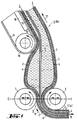
- a flat-lying hose 1 the wall of which consists of three layers, namely from a gas-impermeable outer layer 2, an inner layer 3 from a fiber material 4 and from a gas-impermeable inner layer 5, is fed from the side and conveyed from below into a nip 6, which is formed between two cylindrical rollers 7 and 8. At least one of these rollers 7 and 8 is driven, and the axes of rotation these rollers lie in a common horizontal plane E-E. In this plane, the rollers 7 and 8 are in the direction of the two double arrows adjustable so that the contact pressure of the rollers on the hose 1 and hence the compression and subsequent expansion of the elastic Fiber material 4 can be adjusted.
- hose 1 is evacuated according to arrow 10.
- the absolute flat position of the hose 1 shown in FIG Roll nip 6 forced, the effect of atmospheric pressure acts supportive.
- the outer layer 2 and the inner layer 5 consist of film tubes, which can also have seams, but do not have to.
- the fiber material 4 also has the shape of a Hose on the circumference by one of the usual connection techniques closed is.
- the unimpregnated or "dry" section the hose is designated 1a, the impregnated section of the Hose with 1b.
- the hose 1 then gradually opens in the nip under the effect the geodetic pressure of a curable liquid resin 11, which the fills up the storage volume formed at this point.
- the inner layer 5 remains lying flat on top of each other and floating in the liquid Resin 11.
- the outer layer 2 and Fiber material 4 Due to the formation of the storage volume, the outer layer 2 and Fiber material 4 has a corresponding transverse contraction, so that the inner layer 5 becomes slightly wavy transversely to the direction of transport, but this is important for achieving it the end purpose is not a disadvantage.
- the liquid resin 11 thereby the possibility to flow around the inner layer 5, which was not possible with the previously known methods.
- the impregnated section 1b of the hose 1 subtracted vertically upwards, at least with a vertical movement component, the hose subsequently being on an inclined plane 13 supports, which is formed by the upper run of a conveyor belt 14, which is guided around a deflection roller 15.
- a support plate 16 is provided to support the upper Trumms of the conveyor belt 14. The impregnated Section 1b of the hose is pulled off in the direction of arrow 17.
- deflection roller 15 can also be taken over by the roller 7 will; in this case the conveyor belt 14 is guided around the roller 7.
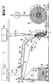
- FIG. 2 shows the subject of Figure 1 on a greatly reduced scale. Where necessary, the same reference numbers have been retained.
- a roller carrier 19 With an axially parallel Slit is formed, in which the hose end 1c is vacuum-tight is inserted.
- a suction line 20 Vacuum pump 21 On the roller carrier 19 is a via a suction line 20 Vacuum pump 21 connected, the air from the unimpregnated section Aspirates 1a of the hose 1.
- the roller carrier 19 is rotatable held between two bearing blocks 22, of which only the rear one is shown is.
- the conveyor belt 14 is guided over three further deflection rollers 23, 24 and 25, of which the run between the deflection rollers 23 and 24 is another inclined plane 26 defined.
- Another support plate 27 is used for support.
- the deflecting roller 25 is mounted in a tensioning device 28, which an arrow is indicated.
- the hose can also be delivered folded in a meander shape. Should the initial evacuation time can be reduced, then it may be appropriate be to insert suction nozzles into the outer layer at intervals in front of the nip and close the puncture holes shortly before the nip.
- hose section 1b of the hose 1 led down and in the form of a meandering Hose stack 29 collected on a transport device 30, which is designed as a pallet.
- the meandering structure of the tube stack 29 is effected by a traversing roller 31, which in the direction of Double arrow 32 between the solid position and the dashed position 31a shown is movable back and forth.
- the bearings and drives of the individual rollers are not shown in detail; It is also not required to drive all of the rollers.
- the hose start 1d is set up approximately vertically, as this is shown in dashed lines above the nip 6. Above the opening formed at the beginning of the hose 1d there is a reservoir 33 for liquid resin, which is metered into the telescopic tube 34 open hose start is entered. The required metering valve is not shown in the drawing. As soon as the fiber material is above the Nip 6 full, i.e. is impregnated air-free, forms within the Nip is a kind of liquid seal, up to which the effect of the vacuum pump 21 is enough.
- the beginning of the hose is 1d under Retaining its opening on the inclined plane 13 filed and over the guide roller 23 and the second inclined plane 26 up to the vicinity of Deflection roller 24 guided, the opening at the hose end 1d 'continues remains directed upwards, as shown in dashed lines on the left in Figure 2.
- the reservoir follows this movement of the beginning of the hose 1d or 1d ' 33 with the liquid resin via a travel path L to a position 33 ', which is shown at the top left in FIG. Then the resin supply is continuous or can be done in portions, interrupted.
- the beginning of the hose 1d ' is then closed by an adhesive tape and placed under a pushed further roller 35, which was previously in a raised position has found.
- a further nip 36 is set with a squeezing effect becomes.
- the nip 36 is also adjustable to in addition to the resin Slope to generate a pressure increase.
- the roller 35 is in the direction of Arrow 35a adjustable to the constantly decreasing storage volume of the To be able to follow Harz. From this it can be seen that a nip is not must necessarily be formed by two rollers, but also can be formed by a roller and a conveyor belt. Even above the deflection roller 24 is in turn a further roller 37, which defines a further nip 38 through which the hose 1 is guided is before it is placed on the tube stack 29.
- the storage volume of the resin 11 extends between the nip 6 and the nip 36.
- the amount of resin in this storage volume corresponds to the amount of resin required for the remaining length of the hose after closing the hose beginning 1d is no longer added.
- Corresponding long is the transport path of the hose 1 between the Roller gap 6 and the roller gap 36 to choose.
- the height difference between the nip 6 and the nip 36 also determines the geodetic pressure across the nip 6 and thus the effectiveness of the impregnation. It is understood that the tendencies of the inclined levels 13 and 26 can be adjustable and the parameters of the Impregnation process can be adjusted.
- the crooked Level 26 is also at least approximately horizontal.
- the impregnated section 1b of the hose 1 is pulled vertically upward from the nip 6; otherwise the procedural conditions and the device details remain largely unchanged. In this case, the whole is for the given The amount of resin required 11 at a time into the tube length Entered the beginning of the hose, but this is not shown here. Also in this case the double, which is only indicated by dashed lines, "floats" Inner layer 5 within the storage volume, and the impregnated section 1b of the hose is passed through a further nip 39, which is formed between two further rollers 40 and 41. This Rollers 40 and 41 are also adjustable in the horizontal direction to the Optimally adjust the squeezing effect within the nip 39 can.
- the impregnated and now lying flat Section 1b of the hose 1 moves over a conveyor belt 14 and in the manner already described as a hose stack 29 on the transport device 30 filed.
- the conveyor belt 14 is only two Deflection rollers 42 and 43 out. All rollers rotate with the same Peripheral speed, possibly driven only a part of the rollers must become. In this case too, the roller bearings and the Adjustment devices not shown.
- the rollers 40 and 41 can be adjustable in the vertical direction, if necessary even by their own weight in connection with not shown Vertical guides. As a result, the rollers 40 and 41 become tracked the shrinking volume of the resin.
- Figure 4 shows the flat lying, impregnated hose 1 between two Squeeze rolls, which may correspond to rolls 40 and 41 in FIG. 3. It can be seen that the rollers 40 and 41 are rounded at their ends and have a working width B that is smaller than the width of the flat bed Hose 1, in such a way that the two longitudinal folds of Hose 1 are not exposed to the pressure of the rollers 40 and 41. This prevents the impregnation or the amount of resin in the area of said longitudinal folds is reduced inadmissibly.
- the measure of Projection D of the hose over the working width B of the rollers 40 and 41 advantageously corresponds to at least twice the wall thickness of the Hose, including the outer layer 2, the fiber material 4th and the inner layer 5.
Landscapes
- Engineering & Computer Science (AREA)
- General Engineering & Computer Science (AREA)
- Mechanical Engineering (AREA)
- Life Sciences & Earth Sciences (AREA)
- Wood Science & Technology (AREA)
- Lining Or Joining Of Plastics Or The Like (AREA)
- Laminated Bodies (AREA)
- Moulding By Coating Moulds (AREA)
- Reinforced Plastic Materials (AREA)
- Rigid Pipes And Flexible Pipes (AREA)
Applications Claiming Priority (2)
| Application Number | Priority Date | Filing Date | Title |
|---|---|---|---|
| DE19637795 | 1996-09-17 | ||
| DE19637795A DE19637795C1 (de) | 1996-09-17 | 1996-09-17 | Verfahren und Vorrichtung zum Herstellen eines Schlauchs zum Auskleiden von Rohrleitungen und Kanalsystemen |
Publications (2)
| Publication Number | Publication Date |
|---|---|
| EP0834392A2 true EP0834392A2 (fr) | 1998-04-08 |
| EP0834392A3 EP0834392A3 (fr) | 1998-10-28 |
Family
ID=7805840
Family Applications (1)
| Application Number | Title | Priority Date | Filing Date |
|---|---|---|---|
| EP97115781A Withdrawn EP0834392A3 (fr) | 1996-09-17 | 1997-09-11 | Procédé et dispositif pour la fabrication d'un tuyau pour le revêtement de conduits et systèmes de canalisations |
Country Status (6)
| Country | Link |
|---|---|
| US (1) | US5846602A (fr) |
| EP (1) | EP0834392A3 (fr) |
| JP (1) | JPH10146896A (fr) |
| CA (1) | CA2214236A1 (fr) |
| DE (1) | DE19637795C1 (fr) |
| PL (1) | PL322129A1 (fr) |
Families Citing this family (12)
| Publication number | Priority date | Publication date | Assignee | Title |
|---|---|---|---|---|
| DE19709350C1 (de) * | 1997-03-07 | 1998-05-28 | Rothenberger Rohrsanierung Gmb | Verfahren und Vorrichtung zum Herstellen eines Schlauchs für die Auskleidung von Rohrleitungen und Kanalsystemen |
| EP0872318A3 (fr) * | 1997-04-15 | 2000-05-24 | BKP Berolina Polyester GmbH & Co. KG | Procédé et dispositif d'imprégnation |
| US6207002B1 (en) * | 1999-04-30 | 2001-03-27 | Gelco Services, Inc. | Resin impregnation of absorbent material |
| US7261788B1 (en) * | 2003-11-07 | 2007-08-28 | Insitaform (Netherlands) B.V. | Preparation of cured in place liner with integral inner impermeable layer |
| US7238251B1 (en) * | 2003-11-07 | 2007-07-03 | Insituform (Netherlands) B.V. | Method of preparing cured in place liner using resin impregnation tower |
| KR100853165B1 (ko) | 2007-07-30 | 2008-08-20 | 미래피앤씨(주) | 경화용수지가 함침된 상·하수관 보강용 튜브 제조방법 및경화용수지 함침장치 |
| US8580364B2 (en) * | 2008-09-19 | 2013-11-12 | Rene Quitter | Cured-in-place liner material and methods and systems for manufacture |
| EP2189263A1 (fr) | 2008-10-23 | 2010-05-26 | Per Aarsleff A/S | Installation d'imprégnation qui n'est pas sous vide |
| CN106584721B (zh) * | 2016-12-22 | 2019-08-13 | 苏州振瑞昌材料科技有限公司 | 一种加热固化装置 |
| CN110193959A (zh) * | 2019-04-12 | 2019-09-03 | 池州普胜电工材料科技有限公司 | 一种扩张性玻璃软管生产装置及其加工方法 |
| DE102020123835B4 (de) | 2020-09-14 | 2023-10-19 | Impreg Gmbh | Verfahren zum Verpacken von Einlegeschläuchen |
| EP4144498B1 (fr) * | 2021-09-06 | 2024-12-04 | Universität Stuttgart | Procédé et dispositif de trempage d'un demi-produit fibreux doté d'un système matriciel liquide |
Family Cites Families (9)
| Publication number | Priority date | Publication date | Assignee | Title |
|---|---|---|---|---|
| GB1340068A (en) * | 1970-09-22 | 1973-12-05 | Insituform Pipes & Structures | Lining of surfaces defining passageways |
| US4368091A (en) * | 1978-12-29 | 1983-01-11 | Tokyo Gas Co. Ltd. | Method for providing the inner surface of a pipe with a flexible tubular lining material through a liquid resin under pressure |
| US4334943A (en) * | 1979-07-30 | 1982-06-15 | Tokyo Gas Kabushiki Kaisha | Method for smoothly evaginating a tubular material under pressure |
| DE3012251C2 (de) * | 1980-03-28 | 1982-07-08 | Hoechst Ag, 6000 Frankfurt | Verfahren zur Herstellung eines Schlauchs auf Basis von Cellulosehydrat mit einem Überzug auf der Innenseite sowie Vorrichtung zur Durchführung des Verfahrens und Verwendung des Schlauchs |
| DE3012250C2 (de) * | 1980-03-28 | 1982-10-14 | Hoechst Ag, 6000 Frankfurt | Verfahren zur Herstellung eines Schlauchs mit einem Filmüberzug aus Kunststoff auf der Innenseite, seine Verwendung, sowie Vorrichtung zur Durchführung des Verfahrens |
| DE3012252C2 (de) * | 1980-03-28 | 1982-09-23 | Hoechst Ag, 6000 Frankfurt | Verfahren zur Herstellung eines Schlauchs auf Basis von Cellulosehydrat mit einem Überzug auf der Innenseite sowie Vorrichtung zur Durchführung des Verfahrens und Verwendung des Schlauchs |
| JPS60228130A (ja) * | 1984-04-25 | 1985-11-13 | Osaka Gas Co Ltd | 管の内面のライニング方法 |
| DE3546417A1 (de) * | 1985-12-31 | 1987-07-16 | Rolining Ag | Verfahren und vorrichtung zur sanierung insbesondere erdverlegter rohrleitungen |
| EP0301204B1 (fr) * | 1987-07-29 | 1991-09-18 | SOFTLINING AG Systems for Relining | Garnissage pour la rénovation interne des conduites et utilisation dudit garnissage |
-
1996
- 1996-09-17 DE DE19637795A patent/DE19637795C1/de not_active Expired - Fee Related
- 1996-11-04 US US08/743,615 patent/US5846602A/en not_active Expired - Fee Related
-
1997
- 1997-08-28 CA CA002214236A patent/CA2214236A1/fr not_active Abandoned
- 1997-09-11 EP EP97115781A patent/EP0834392A3/fr not_active Withdrawn
- 1997-09-16 JP JP9250874A patent/JPH10146896A/ja active Pending
- 1997-09-16 PL PL97322129A patent/PL322129A1/xx unknown
Also Published As
| Publication number | Publication date |
|---|---|
| JPH10146896A (ja) | 1998-06-02 |
| DE19637795C1 (de) | 1997-10-09 |
| PL322129A1 (en) | 1998-03-30 |
| US5846602A (en) | 1998-12-08 |
| EP0834392A3 (fr) | 1998-10-28 |
| CA2214236A1 (fr) | 1998-03-17 |
Similar Documents
| Publication | Publication Date | Title |
|---|---|---|
| DE2848157A1 (de) | Vorrichtung zum aufbringen von fluessigkeit auf ein gewebe | |
| DE3546417A1 (de) | Verfahren und vorrichtung zur sanierung insbesondere erdverlegter rohrleitungen | |
| DE19637795C1 (de) | Verfahren und Vorrichtung zum Herstellen eines Schlauchs zum Auskleiden von Rohrleitungen und Kanalsystemen | |
| EP3359370B1 (fr) | Procédé et dispositif pour fabriquer une gaine de chemisage pour conduites | |
| CH645251A5 (de) | Verfahren zur herstellung einer zigarettenfiltereinheit und einrichtung zur durchfuehrung des verfahrens. | |
| EP1001206B1 (fr) | Méthode et appareil pour la rénovation d'un vieil élément tubulaire enterré | |
| DE102008051121A1 (de) | Vorrichtung und Verfahren zum Drapieren und Vorformen gekrümmter Profilstrukturteile aus Fasergewirken | |
| CH428189A (de) | Verfahren und Vorrichtung zum Herstellen von Rohren | |
| DE3037167A1 (de) | Verfahren und vorrichtung zur herstellung eines im wesentlichen gasfreien verbundmaterials aus kunststoff und fasern | |
| CH396399A (de) | Verfahren und Vorrichtung zur Herstellung von Kunststoff-Formteilen mit in der Wandung angeordneten Verstärkungseinlagen | |
| DE2137059C3 (de) | Vorrichtung zum Herstellen von Kunststoffrohren oder Kunststoffschläuchen mit einer verstärkenden schlauchförmigen Einlage | |
| DE1947894A1 (de) | Vorrichtung zum Herstellen eines Vlieses aus regellos gelagerten Fasern | |
| DE19908309B4 (de) | Vorrichtung zum Zuführen eines Faserbandes zu einem Streckwerk einer Strecke | |
| EP0400573A1 (fr) | Procédé et appareillage pour fabriquer une courroie sans fin enrobée des deux côtés | |
| EP4144498B1 (fr) | Procédé et dispositif de trempage d'un demi-produit fibreux doté d'un système matriciel liquide | |
| DE19709350C1 (de) | Verfahren und Vorrichtung zum Herstellen eines Schlauchs für die Auskleidung von Rohrleitungen und Kanalsystemen | |
| DE3817800A1 (de) | Verfahren und anlage zur herstellung einer faserverstaerkten bahn aus kunstharz, insbesondere von prepreg | |
| EP1793036B1 (fr) | Procédé de fabrication de bandes imperméables pour machines à papier et dispositif de revêtement pour la mise en oeuvre du procédé | |
| DE3909935C2 (de) | Verfahren und Vorrichtung zum Herstellen eines undurchlässigen und biegsamen Bandes oder Schlauches | |
| DE102016014268B4 (de) | Vorrichtung und Verfahren zum Trennen von Pressgutmatten | |
| DE202015002947U1 (de) | Vorrichtung zum Herstellen von Säcken oder Beuteln sowie Säcke oder Beutel | |
| DE2011184A1 (de) | Verfahren und Vorrichtung zum kontinuierlichen Herstellen einer Oberflächenbedeckung aus Kunststoff am Verwendungsort | |
| DE19946379A1 (de) | Maschine zur Herstellung und/oder Bearbeitung einer Materialbahn | |
| DE2526697C2 (de) | Vorrichtung zur Herstellung eines Faservliesbandes | |
| CH517576A (de) | Verfahren und Vorrichtung zur Herstellung von verstärkten Kunststoffzylindern |
Legal Events
| Date | Code | Title | Description |
|---|---|---|---|
| PUAI | Public reference made under article 153(3) epc to a published international application that has entered the european phase |
Free format text: ORIGINAL CODE: 0009012 |
|
| AK | Designated contracting states |
Kind code of ref document: A2 Designated state(s): AT BE CH DE DK ES FI FR GB GR IE IT LI LU MC NL PT SE |
|
| AX | Request for extension of the european patent |
Free format text: AL;LT;LV;RO;SI |
|
| PUAL | Search report despatched |
Free format text: ORIGINAL CODE: 0009013 |
|
| AK | Designated contracting states |
Kind code of ref document: A3 Designated state(s): AT BE CH DE DK ES FI FR GB GR IE IT LI LU MC NL PT SE |
|
| AX | Request for extension of the european patent |
Free format text: AL;LT;LV;RO;SI |
|
| AKX | Designation fees paid | ||
| STAA | Information on the status of an ep patent application or granted ep patent |
Free format text: STATUS: THE APPLICATION IS DEEMED TO BE WITHDRAWN |
|
| 18D | Application deemed to be withdrawn |
Effective date: 19990429 |
|
| REG | Reference to a national code |
Ref country code: DE Ref legal event code: 8566 |