EP0834436A1 - Support-papier pour tube de poignée de chariot de transport ou manutention, et tube de poignée et chariot équipés d'un tel support-papier - Google Patents
Support-papier pour tube de poignée de chariot de transport ou manutention, et tube de poignée et chariot équipés d'un tel support-papier Download PDFInfo
- Publication number
- EP0834436A1 EP0834436A1 EP97402165A EP97402165A EP0834436A1 EP 0834436 A1 EP0834436 A1 EP 0834436A1 EP 97402165 A EP97402165 A EP 97402165A EP 97402165 A EP97402165 A EP 97402165A EP 0834436 A1 EP0834436 A1 EP 0834436A1
- Authority
- EP
- European Patent Office
- Prior art keywords
- ring
- paper holder
- wing
- holder according
- paper
- Prior art date
- Legal status (The legal status is an assumption and is not a legal conclusion. Google has not performed a legal analysis and makes no representation as to the accuracy of the status listed.)
- Withdrawn
Links
- 230000007423 decrease Effects 0.000 claims abstract description 6
- 239000011324 bead Substances 0.000 claims description 14
- 229920003052 natural elastomer Polymers 0.000 claims description 3
- 229920001194 natural rubber Polymers 0.000 claims description 3
- 230000000717 retained effect Effects 0.000 claims description 3
- 229920003051 synthetic elastomer Polymers 0.000 claims description 3
- 239000005061 synthetic rubber Substances 0.000 claims description 3
- 239000013013 elastic material Substances 0.000 claims description 2
- 240000008042 Zea mays Species 0.000 description 2
- 230000014759 maintenance of location Effects 0.000 description 2
- 239000000463 material Substances 0.000 description 2
- 238000004026 adhesive bonding Methods 0.000 description 1
- 230000003247 decreasing effect Effects 0.000 description 1
- 229920001971 elastomer Polymers 0.000 description 1
- 229940082150 encore Drugs 0.000 description 1
- 238000002513 implantation Methods 0.000 description 1
- 230000000149 penetrating effect Effects 0.000 description 1
- 239000005060 rubber Substances 0.000 description 1
- 238000010079 rubber tapping Methods 0.000 description 1
Images
Classifications
-
- B—PERFORMING OPERATIONS; TRANSPORTING
- B42—BOOKBINDING; ALBUMS; FILES; SPECIAL PRINTED MATTER
- B42F—SHEETS TEMPORARILY ATTACHED TOGETHER; FILING APPLIANCES; FILE CARDS; INDEXING
- B42F9/00—Filing appliances with devices clamping file edges; Covers with clamping backs
- B42F9/001—Clip boards
-
- B—PERFORMING OPERATIONS; TRANSPORTING
- B62—LAND VEHICLES FOR TRAVELLING OTHERWISE THAN ON RAILS
- B62B—HAND-PROPELLED VEHICLES, e.g. HAND CARTS OR PERAMBULATORS; SLEDGES
- B62B3/00—Hand carts having more than one axis carrying transport wheels; Steering devices therefor; Equipment therefor
- B62B3/14—Hand carts having more than one axis carrying transport wheels; Steering devices therefor; Equipment therefor characterised by provisions for nesting or stacking, e.g. shopping trolleys
- B62B3/1428—Adaptations for calculators, memory aids or reading aids
Definitions
- the subject of the present invention is a paper support intended to be mounted on the handle tube of the stretcher of a trolley transport or handling.
- document FR-A1-2 713 004 describes a fixed advertising medium on the handle tube of a supermarket cart.
- the object of the present invention is to overcome this drawback.
- a paper holder intended to be mounted on the tube handle of the operating stretcher of a transport trolley or handling, is characterized by the fact that it consists of a part generally cylindrical comprising a ring to which is connected by its core, called hinge, a T-shaped element including a wing, called maneuver, extends over its entire length at a distance from the ring and of which the other wing, called the holding wing, is at a distance from the outer surface of the ring which decreases from its end by which it connects to the core and to the maneuvering wing up to its free end called the support so that a paper can be retained between said bearing end and the ring, said ring being adapted to receive the handle tube of the carriage to be fixed there.
- Such a paper support usable for example to support a list of races performed in a large area, is simple in constitution; her realization is also simple because the part being generally cylindrical it can be obtained by cutting to length a profile whose cross section is that of said room.
- the maneuvering wing has a cross section globally constant and extends parallel to the outer surface of the ring.
- the retaining wing has a decreasing cross section from its end, by which it is connected to the core of the element and to the wing maneuver, towards its free end called support.
- the free bearing end of the retaining wing has on its face facing the ring a support bead and the ring carries on its outer surface a recess adapted to receive at least partially said bead; preferably, the end of the bead which makes facing the recess is, at rest, at a distance from the bottom of the recess which is less than the depth of the hollow.
- the paper is bent here and supported at three points, one point on the end of the bead and two points bordering the recess.
- the ring is extended by a shelf extending tangentially to the ring from the outer surface area of the ring placed in line with the free support end of the retaining wing.
- the paper support is made of an elastic material.
- it is made of natural or synthetic rubber.
- the paper support is adapted to be mounted by force on the handle tube, the cylindrical inner wall of the ring having a diameter slightly smaller than the outside diameter of the handle tube.
- this one may include a pressurizing means urging the free end from the retaining wing to the outer surface of the ring; the means of placing in pressure can be a plate inserted between the maneuvering wing and the ring, and integral with the ring; joining the wafer and the ring can be obtained by a screw which, when the paper support is mounted on the handle tube, crosses the wall of the handle tube.
- the end of the plate is folded back and in contact with the maneuvering wing and the core, at the junction of these; advantageously, the end of the plate is provided with a notch in so that its contact with the maneuvering wing and the core takes place in two zones spaced longitudinally.
- the present invention also relates to a handle tube of maneuvering stretcher of a transport or handling trolley equipped with a paper holder as above.
- Another object of the invention is a transport cart or handling whose stretcher includes such a handle tube.
- FIG 1 there is partially shown in perspective a carriage 1, of the type used in supermarkets; cart 1 comprises an operating stretcher 2 provided with a handle tube 3 which carries a paper holder 4 according to the invention.
- the paper support 4 consists of a generally cylindrical part comprising a ring 9 to which is connected by its core 11 a T-shaped element including a wing 12, called maneuver, extends over its entire length at a distance from the ring 9 while the other wing 13, called the holding wing, is at a distance from the outer surface 14 of the ring 9 which decreases from its end by which it is connected to the core 12 and to the maneuvering wing 12 to its free end 15 called support, so that a paper 16 can be retained between this end 15 and the ring 9, under the conditions described below.
- the maneuvering wing 12 has a cross section overall constant and extends parallel to the outer surface 14 of the ring 9.
- the retaining wing 13 has a cross section which decreases from its end, by which it is connected to the core 11 and to the operating wing 12, towards its free support end 15.
- the bearing end 15 of the retaining wing 13 has on its face facing the ring 9 a bead 17; ring 9 wears on its surface exterior 14 a recess 18 adapted to receive at least partially the bead 17; as can be seen in Figure 2, the end 19, of the bead 17, which faces the recess 18 is, at rest, at a distance from the bottom thereof which is less than the depth of the recess 18.
- the paper holder 4 is secured to the handle tube 3 by any means appropriate; it can be by gluing, by screwing, by force fitting: in which case the cylindrical inner wall 20 of the ring 9 has a diameter slightly smaller than the outside diameter of the handle tube 3.
- the operation is as follows.
- the core 11 being provided with a thickness less than that of the maneuvering wing 12, it acts as hinge for the assembly constituted by the operating wings 12 and holding 13; therefore, an action exerted on the maneuvering wing 12 in direction of the handle tube 3 slightly tilt said assembly around of this hinge 11 which moves the free end away from the retaining wing 13 of the ring 9 sufficiently so that the end 19 of the bead 17 leaves the recess 19 completely up to a distance from the axis of the handle tube 3, slightly greater than the radius of the outer wall of the ring 9; in this position, it is easy to slide a paper, such as the paper 16, in the slot defined between the retaining wing 13 and the ring 9.
- Figure 4 shows the paper holder 4 equipped with such a means, here a plate 30, pressurization.
- the plate 30, better visible in FIG. 5, comprises a blank 31 of generally rectangular shape, one edge of which is provided with a notch 33; the non-scalloped portions 32 of this edge are folded back to fit substantially the bottom of the groove defined between the ring 9 and the wing of operation 12 when the plate 30 is introduced into this groove, its blank 31 being disposed tangentially to the ring 9 and the folded edges 32 extending from the side of the plate 30 which faces the ring 9.
- a hole 34 is provided in the blank 34 for fixing the plate 30.
- the pressurizing wing 13 is pressurized as follows. In moving relative to the ring 9, before fixing it, the plate 30, previously introduced into the groove defined above, clockwise compared to the figures, the folded edges 32 slightly raise the wing of maneuver 12 and slightly move the core 11 circumferentially, all at least the part of it furthest from the ring 9: this has for as a result, the end 15 of the retaining wing 13 is brought together towards the ring 9 and pressurizing it in contact with the ring 9.
- This pressure position is maintained by securing the wafer 30 to the ring 9; here, this is obtained by a screw 35, passing through the hole 34 and screwed into the ring 9; preferably, as shown, the screw 35 is also screwed into the wall of the handle tube 3; its implementation is made easier by choosing a self-tapping screw 35, the handle tube 3 being metallic.
- the notch 33 with which the plate 30 is provided has the advantage following.
- the material of the paper backing is rather elastic, and this is particularly the case when it is made of rubber, natural or synthetic, when pressed near its center on the wing of maneuver 12, we can take advantage of the available stroke up to ring 9, the maneuvering wing 12 arching at the right of the notch 33, as the shows Figure 6, and the end 15 of the retaining wing 13 is raised at the maximum.
- Figures 7 and 8 show a variant in which a paper support 40, comprising, as in the previous variants, a ring 49, a core 41, and maneuvering wings 42 and holding wings 43, is provided an extension 50 constituting a shelf serving as support for the paper 16 on which it is then possible to write: it is thus possible, for example, when the paper carries a shopping list, cross out the shopping as you go that they are done.
- the tablet 50 extends tangentially to the ring 49 from the area of the outer surface 44 of the ring 49 placed at right from the bearing end of the retaining wing 43; it is better, see imperative, to produce such a paper support 40 in a non-aggressive material, like natural or synthetic rubber; indeed, given its implantation on the handle tube 3, the paper holder 40 must not be dangerous for the child possibly seated at the front of the trolley 1, facing the handle tube 3.
Landscapes
- Engineering & Computer Science (AREA)
- Chemical & Material Sciences (AREA)
- Combustion & Propulsion (AREA)
- Transportation (AREA)
- Mechanical Engineering (AREA)
- Handcart (AREA)
Abstract
Description
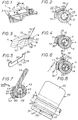
- la figure 1 est une vue partielle en perspective d'un chariot dont le tube de poignée porte un support-papier selon l'invention ;
- la figure 2 est une vue en coupe, à plus grande échelle, selon ll-ll de la figure 1 ;
- la figure 3 est un détail de la figure 2 à plus grande échelle ;
- la figure 4 est analogue à la figure 2 mais concerne une variante ;
- la figure 5 est une vue en perspective de la plaquette qui équipe la variante de la figure 4 ;
- la figure 6 représente le support-papier de la figure 4 dans la position qu'il occupe juste avant la mise en place du papier qu'il doit supporter ;
- la figure 7 est analogue à la figure 4 mais représente encore une autre variante ;
- la figure 8 est une vue selon la flèche VIII de la figure 7.
Claims (16)
- Support-papier constitué d'une pièce à laquelle est raccordé par son âme (11, 41), dite charnière, un élément en forme de T dont une aile (12, 42), dite de manoeuvre, s'étend sur toute sa longueur à distance de ladite pièce et dont l'autre aile (13, 43), dite de maintien, est à une distance de la surface extérieure (14) de ladite pièce qui décroít depuis son extrémité par laquelle elle se raccorde à l'âme (11, 41) et à l'aile de manoeuvre (12, 42) jusqu'à son extrémité libre (15) dite d'appui en sorte qu'un papier peut être retenu entre ladite extrémité d'appui et ladite pièce, caractérisé par le fait que ladite pièce est une pièce globalement cylindrique comportant un anneau (9, 49), ledit anneau étant adapté à recevoir le tube de poignée (3) du brancard de manoeuvre (2) d'un chariot (1) de transport ou manutention pour y être fixé.
- Support-papier selon la revendication 1, caractérisé par le fait que l'aile de manoeuvre (12, 42) a une section transversale globalement constante et s'étend parallèlement à la surface extérieure (14) de l'anneau (9, 49).
- Support-papier suivant l'une des revendications 1 ou 2, caractérisé par le fait que l'aile de maintien (13, 43) a une section transversale qui décroít depuis son extrémité, par laquelle elle est reliée à l'âme (11, 41) de l'élément et à l'aile de manoeuvre (12, 42), vers son extrémité libre (15) dite d'appui.
- Support-papier suivant l'une des revendications 1 à 3, caractérisé par le fait que l'extrémité libre (15) d'appui de l'aile de maintien (13, 43) présente sur sa face tournée vers l'anneau (9, 49) un bourrelet (17) d'appui et l'anneau (9, 49) porte à sa surface extérieure (14) une creusure (18) adaptée à recevoir au moins partiellement ledit bourrelet (17).
- Support-papier selon la revendication 4, caractérisé par le fait que l'extrémité (19) du bourrelet (17) qui fait face à la creusure (18) est, au repos, à une distance du fond de la creusure (18) qui est inférieure à la profondeur de la creusure (18).
- Support-papier selon l'une des revendications 1 à 5, caractérisé par le fait que l'anneau (49) est prolongé par une tablette (50) s'étendant tangentiellement à l'anneau (49) depuis la zone de la surface extérieure (44) de l'anneau (49) placée au droit de l'extrémité libre d'appui de l'aile de maintien (43).
- Support-papier selon l'une des revendications 1 à 6, caractérisé par le fait qu'il est réalisé en une matière élastique.
- Support-papier selon la revendication 7, caractérisé par le fait qu'il est réalisé en caoutchouc naturel ou synthétique.
- Support-papier selon l'une des revendications 1 à 8, caractérisé par le fait qu'il est adapté à être monté à force sur le tube de poignée (3), la paroi intérieure (20) cylindrique de l'anneau (9) ayant un diamètre légèrement inférieur au diamètre extérieur du tube de poignée (3).
- Support-papier selon l'une des revendications 1 à 9, caractérisé par le fait qu'il comporte un moyen de mise en pression (30) sollicitant l'extrémité libre (15) de l'aile de maintien (13, 43) vers la surface extérieure (14, 44) de l'anneau (9, 49).
- Support-papier selon la revendication 10, caractérisé par le fait que le moyen de mise en pression (30) est une plaquette insérée entre l'aile de manoeuvre (12, 42) et l'anneau (9, 49), et solidaire de l'anneau (9, 49).
- Support-papier selon la revendication 11, caractérisé par le fait que la solidarisation de la plaquette (30) et de l'anneau (9, 49) est obtenue par une vis (35) qui, lorsque le support-papier (4, 40) est monté sur le tube de poignée (3), traverse la paroi du tube de poignée (3).
- Support-papier selon l'une des revendications 11 ou 12, caractérisé par le fait que l'extrémité de la plaquette (30) est repliée (32) et en contact avec l'aile de manoeuvre (12, 42) et l'âme (11, 41), au droit de la jonction de celles-ci.
- Support-papier selon la revendication 13, caractérisé par le fait que l'extrémité de la plaquette (30) est munie d'une échancrure (33) en sorte que son contact avec l'aile de manoeuvre (12, 42) et l'âme (11, 41) a lieu en deux zones espacées longitudinalement.
- Tube de poignée de brancard de manoeuvre d'un chariot de transport ou manutention équipé d'un support-papier (4, 40) selon les revendications 1 à 14.
- Chariot de transport ou manutention dont le brancard (2) comporte un tube de poignée selon la revendication 15.
Applications Claiming Priority (2)
| Application Number | Priority Date | Filing Date | Title |
|---|---|---|---|
| FR9611946A FR2753950B1 (fr) | 1996-10-01 | 1996-10-01 | Support-papier pour tube de poignee de chariot de transport ou manutention, et tube de poignee et chariot equipes d'un tel support-papier |
| FR9611946 | 1996-10-01 |
Publications (1)
| Publication Number | Publication Date |
|---|---|
| EP0834436A1 true EP0834436A1 (fr) | 1998-04-08 |
Family
ID=9496233
Family Applications (1)
| Application Number | Title | Priority Date | Filing Date |
|---|---|---|---|
| EP97402165A Withdrawn EP0834436A1 (fr) | 1996-10-01 | 1997-09-18 | Support-papier pour tube de poignée de chariot de transport ou manutention, et tube de poignée et chariot équipés d'un tel support-papier |
Country Status (2)
| Country | Link |
|---|---|
| EP (1) | EP0834436A1 (fr) |
| FR (1) | FR2753950B1 (fr) |
Cited By (3)
| Publication number | Priority date | Publication date | Assignee | Title |
|---|---|---|---|---|
| FR2795033A1 (fr) * | 1999-06-17 | 2000-12-22 | Aline Marie Claude Maubon | Support pour papier adaptable a la poignee d'un chariot de magasin |
| EP2333755A1 (fr) * | 2009-12-14 | 2011-06-15 | Bela Solutions | Support de visuel pour chariot de point de vente |
| USD734587S1 (en) | 2014-01-29 | 2015-07-14 | Tomer Golan | Shopping cart-ring shaped paper holder |
Families Citing this family (1)
| Publication number | Priority date | Publication date | Assignee | Title |
|---|---|---|---|---|
| DE10351846A1 (de) * | 2003-11-06 | 2005-06-09 | Franz Kahl Gmbh | Hubwagendeichsel |
Citations (5)
| Publication number | Priority date | Publication date | Assignee | Title |
|---|---|---|---|---|
| US3388493A (en) * | 1966-10-05 | 1968-06-18 | James M. Greenwell | Clamping device combined with a shopping basket |
| US3539204A (en) * | 1968-05-03 | 1970-11-10 | Theodore F Keller | Clip board for a shopping cart |
| DE3019707A1 (de) * | 1980-05-23 | 1981-12-10 | Elba-Ordner-Fabrik Kraut & Meienborn GmbH & Co., 5600 Wuppertal | Haltevorrichtung fuer blattfoermige gegenstaende |
| GB2188867A (en) * | 1986-04-11 | 1987-10-14 | David Malcolm Pike | A clipboard |
| FR2713004A1 (fr) | 1993-11-26 | 1995-06-02 | Collet Pierre | Support publicitaire fixe sur un manche de chariot de supermarché. |
-
1996
- 1996-10-01 FR FR9611946A patent/FR2753950B1/fr not_active Expired - Fee Related
-
1997
- 1997-09-18 EP EP97402165A patent/EP0834436A1/fr not_active Withdrawn
Patent Citations (5)
| Publication number | Priority date | Publication date | Assignee | Title |
|---|---|---|---|---|
| US3388493A (en) * | 1966-10-05 | 1968-06-18 | James M. Greenwell | Clamping device combined with a shopping basket |
| US3539204A (en) * | 1968-05-03 | 1970-11-10 | Theodore F Keller | Clip board for a shopping cart |
| DE3019707A1 (de) * | 1980-05-23 | 1981-12-10 | Elba-Ordner-Fabrik Kraut & Meienborn GmbH & Co., 5600 Wuppertal | Haltevorrichtung fuer blattfoermige gegenstaende |
| GB2188867A (en) * | 1986-04-11 | 1987-10-14 | David Malcolm Pike | A clipboard |
| FR2713004A1 (fr) | 1993-11-26 | 1995-06-02 | Collet Pierre | Support publicitaire fixe sur un manche de chariot de supermarché. |
Cited By (4)
| Publication number | Priority date | Publication date | Assignee | Title |
|---|---|---|---|---|
| FR2795033A1 (fr) * | 1999-06-17 | 2000-12-22 | Aline Marie Claude Maubon | Support pour papier adaptable a la poignee d'un chariot de magasin |
| EP2333755A1 (fr) * | 2009-12-14 | 2011-06-15 | Bela Solutions | Support de visuel pour chariot de point de vente |
| FR2953971A1 (fr) * | 2009-12-14 | 2011-06-17 | Bela Solutions | Support de visuel pour chariot de point de vente |
| USD734587S1 (en) | 2014-01-29 | 2015-07-14 | Tomer Golan | Shopping cart-ring shaped paper holder |
Also Published As
| Publication number | Publication date |
|---|---|
| FR2753950A1 (fr) | 1998-04-03 |
| FR2753950B1 (fr) | 1998-12-04 |
Similar Documents
| Publication | Publication Date | Title |
|---|---|---|
| EP0367640B1 (fr) | Plot de fixation pour montages divers et support quelconque équipé de ce plot | |
| WO1998026686A1 (fr) | Articulation a ressort pour article de chevelure | |
| CH710995A2 (fr) | Montre destinée à être montée sur un support amovible. | |
| FR2577291A1 (fr) | Butee d'embrayage autocentreuse, notamment pour vehicule automobile, a assemblage compact simplifie | |
| FR2807689A1 (fr) | Couteau pliant | |
| EP0380597A1 (fr) | Dispositif de frein pour patins et planches a roulettes | |
| FR2681918A1 (fr) | Dispositif pour l'assemblage et le desassemblage rapide de deux pieces l'une sur l'autre. | |
| EP0834436A1 (fr) | Support-papier pour tube de poignée de chariot de transport ou manutention, et tube de poignée et chariot équipés d'un tel support-papier | |
| EP0286561B1 (fr) | Collier à vis de serrage pivotante | |
| FR2647393A1 (fr) | Stylo ou objet analogue a agrafe perfectionnee | |
| BE1014865A3 (fr) | Dispositif de fixation amovible d'un aviron sur une | |
| FR2796344A1 (fr) | Mecanisme d'ancrage et d'articulation, notamment pour un siege arriere d'un vehicule automobile | |
| FR2575704A1 (fr) | Instrument d'ecriture du type stylo, crayon ou analogue a pointe d'ecriture escamotable | |
| FR2732884A1 (fr) | Suceur d'aspirateur avec des roues arrieres | |
| FR2759126A1 (fr) | Dispositif d'immobilisation relative de deux tubes ou d'un tube et d'une paroi a double peau et tricycle comprenant deux tubes immobilises grace a un tel dispositif | |
| FR3070756B1 (fr) | Accessoire d’aide au reglage de l’alignement d’une roue avant d’une bicyclette par rapport a la potence de son guidon | |
| EP2868933A1 (fr) | Elément de blocage d'au moins deux tubes enfiles l'un dans l'autre, et structure de liaison à tubes télescopiques le comprenant | |
| EP1084766B1 (fr) | Dispositif à peindre à élément de maintien de rouleau adaptable au rouleau | |
| FR2738540A1 (fr) | Pare-chocs pour chariot et chariot equipe d'un tel pare-chocs | |
| EP1114702B1 (fr) | Rouleau à peindre à manchon teléscopique à manipulation facilitée | |
| FR3058089B1 (fr) | Roulette | |
| FR2719749A1 (fr) | Dispositif de fixation amovible d'une visière sur un casque. | |
| WO1994027422A2 (fr) | Garniture pour clef | |
| EP1889668B1 (fr) | Système de verrouillage déverrouillage pour rouleau à peindre | |
| FR3041567A1 (fr) | Assemblage d'une roue et d'un enjoliveur |
Legal Events
| Date | Code | Title | Description |
|---|---|---|---|
| PUAI | Public reference made under article 153(3) epc to a published international application that has entered the european phase |
Free format text: ORIGINAL CODE: 0009012 |
|
| AK | Designated contracting states |
Kind code of ref document: A1 Designated state(s): BE DE ES GB IT LU NL |
|
| AX | Request for extension of the european patent |
Free format text: AL;LT;LV;RO;SI |
|
| 17P | Request for examination filed |
Effective date: 19980507 |
|
| AKX | Designation fees paid |
Free format text: BE DE ES GB IT LU NL |
|
| RBV | Designated contracting states (corrected) |
Designated state(s): BE DE ES GB IT LU NL |
|
| 17Q | First examination report despatched |
Effective date: 20000323 |
|
| GRAG | Despatch of communication of intention to grant |
Free format text: ORIGINAL CODE: EPIDOS AGRA |
|
| GRAG | Despatch of communication of intention to grant |
Free format text: ORIGINAL CODE: EPIDOS AGRA |
|
| GRAH | Despatch of communication of intention to grant a patent |
Free format text: ORIGINAL CODE: EPIDOS IGRA |
|
| STAA | Information on the status of an ep patent application or granted ep patent |
Free format text: STATUS: THE APPLICATION IS DEEMED TO BE WITHDRAWN |
|
| 18D | Application deemed to be withdrawn |
Effective date: 20010807 |