EP0834437B1 - Ensemble d'une colonne de direction d'un véhicule automobile - Google Patents
Ensemble d'une colonne de direction d'un véhicule automobile Download PDFInfo
- Publication number
- EP0834437B1 EP0834437B1 EP97116143A EP97116143A EP0834437B1 EP 0834437 B1 EP0834437 B1 EP 0834437B1 EP 97116143 A EP97116143 A EP 97116143A EP 97116143 A EP97116143 A EP 97116143A EP 0834437 B1 EP0834437 B1 EP 0834437B1
- Authority
- EP
- European Patent Office
- Prior art keywords
- steering column
- spindle
- motor vehicle
- adjusting
- vehicle steering
- Prior art date
- Legal status (The legal status is an assumption and is not a legal conclusion. Google has not performed a legal analysis and makes no representation as to the accuracy of the status listed.)
- Expired - Lifetime
Links
- 230000007246 mechanism Effects 0.000 claims description 30
- 230000002093 peripheral effect Effects 0.000 claims description 4
- 238000010276 construction Methods 0.000 claims description 3
- 238000006073 displacement reaction Methods 0.000 description 2
- 238000009434 installation Methods 0.000 description 2
- 238000004519 manufacturing process Methods 0.000 description 2
- 230000005284 excitation Effects 0.000 description 1
- 238000003780 insertion Methods 0.000 description 1
- 230000037431 insertion Effects 0.000 description 1
- 208000016261 weight loss Diseases 0.000 description 1
- 238000004804 winding Methods 0.000 description 1
Images


Classifications
-
- B—PERFORMING OPERATIONS; TRANSPORTING
- B62—LAND VEHICLES FOR TRAVELLING OTHERWISE THAN ON RAILS
- B62D—MOTOR VEHICLES; TRAILERS
- B62D1/00—Steering controls, i.e. means for initiating a change of direction of the vehicle
- B62D1/02—Steering controls, i.e. means for initiating a change of direction of the vehicle vehicle-mounted
- B62D1/16—Steering columns
- B62D1/18—Steering columns yieldable or adjustable, e.g. tiltable
- B62D1/181—Steering columns yieldable or adjustable, e.g. tiltable with power actuated adjustment, e.g. with position memory
Definitions
- the invention relates to a motor vehicle steering column unit with a steering column housing and a steering column arranged therein and an electrically driven adjusting device for longitudinal adjustment and inclination adjustment of the steering column.
- Motor vehicle steering column units are known and are in large numbers of the automotive industry in passenger cars as well Load goods installed. This is the basic structure of such units characterized in that usually for each adjustment direction, i.e. for both Longitudinal adjustment as well as a separate adjustment for the inclination of the steering column electric drive unit is used. Motor vehicle steering column units with this Construction has proven itself in practice, but due to its high level Parts requirements and the resulting increased assembly costs are high overall Manufacturing costs. An additional disadvantage of the usual structure is that the individual electric drive units require considerable space in the area the motor vehicle steering column unit. In addition, the usual one Construction also negative from the point of view of possible weight reductions judge.
- a tilting and / or telescopic steering column is known according to the preamble of claim 1 for each of these two functions (tilt and telescope) a separate one or for both functions only require an electric motor. It is said to be a brushless one DC motor can be used.
- This steering column has two telescopic Sections and a tiltable section. The tilting movement is one Swivel axis.
- the DC motor drives an axial, multi-part adjusting spindle, which engages with an adjusting mechanism via an electromagnetic clutch stands for the supply of their excitation winding with rotating adjusting spindle for one Axial movement ensures.
- the adjusting spindle is designed, for example, in two parts, wherein a universal joint is inserted between the two parts to perform a tilting function To ensure steering column.
- articulated connections always tend to wear faster, so that a trouble-free and noiseless function of the steering column only for a limited number Period can be guaranteed, if this is possible at all.
- Second are for such steering columns additional components (joint and two adjusting spindles) required.
- the case with such a steering column design occur that the tilting movement is prevented by self-locking of the system. This is always the case when the drive spindles and the steering column are exactly parallel and run in the axial direction. Tilting of the steering column is only possible when An external force that deviates from the axial direction acts on the system for example, must be applied by the driver.
- the object of the present invention is therefore to provide a motor vehicle steering column unit to further develop the generic type in such a way that its structure is simplified as well as manufacturing costs, space requirements and weight compared to conventional designs be significantly reduced.
- This design according to the invention has the great advantage that for desired adjustment in two different directions now only one electric drive unit is required.
- the respective adjustment mechanisms for Longitudinal movement and the inclination movement of the steering column are one common adjustment spindle driven, the control of the adjustment mechanisms separately by switching the adjustment mechanisms on and off arranged switching devices can be made. There is therefore no need for one complete electric drive unit with all its space, weight and and cost disadvantages.
- the space requirement of the motor vehicle steering column unit according to the invention is still additionally reduced by the fact that the adjustment mechanism for the longitudinal movement of the Steering column is connected directly to the steering column housing via a connecting lever.
- the adjustment mechanism for tilting the steering column has expediently in analogy to the adjustment mechanism of the longitudinal movement corresponding rocker arm in which the axial bearing of the corresponding spindle nut is set.
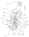
- the motor vehicle steering column unit designated by the reference number 1 in FIG. 1 has a steering column 5, a steering column housing 6 and one in its entirety with 3 designated adjusting device, wherein the adjusting device from a drive unit 10 and two adjustment mechanisms 20 and 40.
- the adjustment mechanism 20 is used in this embodiment for the longitudinal adjustment of the steering column 5, whereas the adjustment mechanism 40 for tilt adjustment of the steering column 5 serves.
- the drive unit 10 consists essentially of an electric motor gear unit 11 with flanged electric motor 15 and internal one, not shown here Spindle bearing.
- the drive unit 10 serves to drive the adjusting spindle 12, which in the electric motor-gear unit 11 in the axial longitudinal direction of the Spindle center axis is fixed so that the adjusting spindle 12 only one rotary movement can perform.
- On the adjusting spindle 12 there are two spindle nuts 21 side by side or 41 arranged, the spindle nut 21 to the adjustment mechanism 20 of the longitudinal adjustment and the spindle nut 41 to the adjustment mechanism 40 for the Inclination adjustment belongs.
- the spindle nuts arranged on the adjusting spindle 12 21 and 41 are each surrounded by a bearing housing 32 and 52.
- the bearing housing 32 belongs to the connecting lever 30, which is firmly connected to the steering column housing 6 is.
- the bearing housing 52 is connected to the rocker arm 50 via a swivel joint 51, which serves to adjust the inclination of the steering column housing
- Rotary movement of the adjusting spindle 12 is a rectified rotational movement of the two Spindle nuts 21 and 41 without changing the position of the threaded spindles in the axial Longitudinal direction of the spindle axis takes place.
- Both adjustment mechanisms 20 and 40 are each equipped with a switching device 24 or 44 provided, which are designed as a solenoid in the example shown here.
- the 4 shows clearly that the respective bearing housing 32nd or 52 adjacent solenoids each have a pin 25 or 45, from the solenoid housing when the solenoid is actuated in the direction of the Center axis of the drive spindle 12 is extendable.
- the switching device 44 shown with applied switching voltage, in which the pin 45 of the solenoid in a Corresponding recess 46 of the spindle nut 41 engages.
- each Recesses in the form of a toothing facilitate the intervention of the corresponding one Pin 25 or 45 in the recess opposite the pen tip the spindle nuts 21 and 41.
- the two adjustment mechanisms 20 and 40 are for the Tilt and longitudinal adjustment in a row in a side area of the adjustment spindle arranged, the drive unit for the adjusting spindle 12 is located the other end of the adjusting spindle facing away from the adjusting mechanisms 20 or 40 12.
- Motor vehicle steering column unit make it necessary is of course also one Installation position of the drive unit 10 conceivable such that a Adjustment mechanism 20 or 40 is placed on one side of the drive unit 10.
- the Drive unit 10 would thus be between the two adjustment mechanisms 20 and 40 arranged, the bearing of the drive spindle 12 thus centrally between the Adjustment mechanisms for the longitudinal or incline adjustment within the electric motor gear unit 11 realized.
Landscapes
- Engineering & Computer Science (AREA)
- Chemical & Material Sciences (AREA)
- Combustion & Propulsion (AREA)
- Transportation (AREA)
- Mechanical Engineering (AREA)
- Steering Controls (AREA)
- Power Steering Mechanism (AREA)
Claims (9)
- Unité de colonne de direction (1) pour véhicule automobile comportant un boítier de colonne de direction (6) et une colonne de direction (5) située dans ce boítier et un dispositif de réglage (3) actionné électriquement, servant à réaliser le réglage longitudinal et le réglage d'inclinaison de la colonne de direction (5), et dans laquelle le dispositif de réglage (3) porte une unité d'entraínement électrique (10) pour entraíner en rotation une broche de réglage (12) et pour déplacer longitudinalement et incliner au moins respectivement un mécanisme de réglage (20, 40) et, pour chaque direction de déplacement, un dispositif de commutation (21, 44), et un écrou de broche (20, 41) disposé au voisinage de ce dispositif, et dans laquelle une liaison de force peut être établie entre le dispositif de commutation respectif (24, 44) et l'écrou. de broche (21, 41) voisin du dispositif de commutation, caractérisée en ce quela broche de réglage (12) est réalisée d'un seul tenant, etles écrous de broche (21, 41) sont disposés sur la broche de réglage d'un seul tenant (12) et sont montés de manière à être déplaçables dans la direction axiale de la broche de réglage (12).
- Unité de colonne de direction pour véhicule automobile selon la revendication 1, caractérisée en ce que les dispositifs de commutation (24, 44) sont agencés sous la forme d'un aimant de levage pourvu d'une tige déplaçable (25, 45), les tiges (25, 45) pouvant être introduites dans des évidements respectifs correspondants (26, 46) des écrous de broche (21, 41).
- Unité de colonne de direction pour véhicule automobile selon la revendication 2, caractérisée en ce que plusieurs évidements correspondants (26, 46) sont disposés sur la surface périphérique (27, 47) du côté de la face extérieure de l'écrou de broche d'une manière concentrique à l'axe médian de l'écrou de broche.
- Unité de colonne de direction pour véhicule automobile selon la revendication 3, caractérisée en ce que les évidements fournissent la forme géométrique d'une denture (29, 49).
- Unité de colonne de direction pour véhicule automobile selon la revendication 1, caractérisée en ce que le mécanisme de réglage (20) est relié directement au boítier (6) de la colonne de direction, pour le déplacement longitudinal de la colonne de direction.
- Unité de colonne de direction pour véhicule automobile selon la revendication 1, caractérisée en ce que le mécanisme de réglage (20) est relié directement au boítier (6) de la colonne de direction pour déplacer longitudinalement la colonne de direction, le système de tourillonnage axial de l'écrou de broche correspondant (22, 23) étant logé dans un levier de liaison (30) du mécanisme de réglage (20).
- Unité de colonne de direction pour véhicule automobile selon la revendication 1, caractérisée en ce que le mécanisme de réglage (40) possède, pour le mouvement d'inclinaison de la colonne de direction, un levier basculant (50), dans lequel est fixé le système de tourillonnage axial (42, 43) de l'écrou de broche correspondant (41).
- Unité de colonne de direction pour véhicule automobile selon une ou plusieurs des revendications précédentes, caractérisée en ce que l'unité d'entraínement (10) contient une unité de construction moteur électrique - mécanisme (11) comportant un support intégré pour la broche de réglage (12).
- Unité de colonne de direction pour véhicule automobile selon une ou plusieurs des revendications précédentes, caractérisée en ce que l'unité d'entraínement (10) peut pivoter, lors du mouvement d'inclinaison de la colonne de direction, autour du centre de rotation (9).
Applications Claiming Priority (2)
| Application Number | Priority Date | Filing Date | Title |
|---|---|---|---|
| DE19641152A DE19641152C2 (de) | 1996-10-07 | 1996-10-07 | Kraftfahrzeuglenksäuleneinheit |
| DE19641152 | 1996-10-07 |
Publications (3)
| Publication Number | Publication Date |
|---|---|
| EP0834437A2 EP0834437A2 (fr) | 1998-04-08 |
| EP0834437A3 EP0834437A3 (fr) | 1998-11-11 |
| EP0834437B1 true EP0834437B1 (fr) | 2001-11-07 |
Family
ID=7807978
Family Applications (1)
| Application Number | Title | Priority Date | Filing Date |
|---|---|---|---|
| EP97116143A Expired - Lifetime EP0834437B1 (fr) | 1996-10-07 | 1997-09-17 | Ensemble d'une colonne de direction d'un véhicule automobile |
Country Status (8)
| Country | Link |
|---|---|
| US (1) | US6079743A (fr) |
| EP (1) | EP0834437B1 (fr) |
| JP (1) | JPH10119793A (fr) |
| KR (1) | KR100465005B1 (fr) |
| BR (1) | BR9704980A (fr) |
| DE (2) | DE19641152C2 (fr) |
| ES (1) | ES2165554T3 (fr) |
| ZA (1) | ZA978833B (fr) |
Families Citing this family (37)
| Publication number | Priority date | Publication date | Assignee | Title |
|---|---|---|---|---|
| DE10144476A1 (de) * | 2001-09-10 | 2003-03-27 | Nacam Deutschland Gmbh | Kraftfahrzeuglenksäuleneinheit mit verstellbarer Lenksäule |
| DE10251764A1 (de) | 2002-11-07 | 2004-05-27 | Daimlerchrysler Ag | Kraftfahrzeuglenksäule |
| DE10301142B3 (de) | 2003-01-14 | 2004-08-12 | Nacam Deutschland Gmbh | Lenksäule für ein Kraftfahrzeug |
| DE10326119B3 (de) * | 2003-06-06 | 2005-02-03 | Nacam Deutschland Gmbh | Kraftfahrzeuglenksäuleneinheit |
| DE10341419A1 (de) | 2003-09-09 | 2005-03-31 | Daimlerchrysler Ag | Kraftfahrzeuglenksäuleneinheit |
| DE102004009725B4 (de) * | 2004-02-25 | 2007-08-30 | Zf Lenksysteme Nacam Gmbh | Kupplungsmechanismus |
| DE102004009906B3 (de) * | 2004-02-26 | 2005-07-28 | Nacam Deutschland Gmbh | Wälzlager mit einstellbarer Kraftübertragung |
| US7255368B2 (en) * | 2004-06-09 | 2007-08-14 | Delphi Technologies, Inc. | Apparatus for steering column tilt and telescope function |
| FR2874885B1 (fr) * | 2004-09-08 | 2006-12-29 | Nacam France Sas | Module de colonne de direction a commande de positionnement motorise |
| DE102004049960A1 (de) * | 2004-10-13 | 2006-04-20 | Ims Gear Gmbh | Lenksäulen-Höhenverstellvorrichtung |
| KR100580534B1 (ko) * | 2005-01-03 | 2006-05-15 | 현대자동차주식회사 | 기어를 이용한 틸트·텔레스코픽 모드 변경 타입 모터구동식 조향장치 |
| US20060283281A1 (en) * | 2005-06-20 | 2006-12-21 | Xiaoyu Li | Synchronized screw driven power telescoping and tilt mechanism for steering column |
| JP4648810B2 (ja) * | 2005-09-28 | 2011-03-09 | 富士機工株式会社 | 電動チルトテレスコステアリングコラム |
| JP5125253B2 (ja) * | 2007-06-26 | 2013-01-23 | アイシン精機株式会社 | 車両のステアリング装置 |
| JP5161534B2 (ja) * | 2007-10-19 | 2013-03-13 | 富士機工株式会社 | 電動チルトステアリング装置 |
| JP5513282B2 (ja) * | 2010-06-29 | 2014-06-04 | 富士機工株式会社 | 電動テレスコステアリング装置 |
| KR101338645B1 (ko) * | 2010-12-06 | 2013-12-06 | 현대자동차주식회사 | 단일 모터 타입 전동컬럼장치 |
| DE102012000635A1 (de) | 2012-01-14 | 2013-07-18 | Daimler Ag | Spindeltrieb zur Höhenverstellung einer elektrisch verstellbaren Lenksäule |
| US9254861B2 (en) | 2012-05-25 | 2016-02-09 | Nsk Ltd. | Electric steering wheel position adjustment apparatus |
| US10228047B2 (en) | 2016-06-17 | 2019-03-12 | Robert Bosch Llc | Actuator for providing relative motion between two points |
| US10279834B2 (en) | 2016-09-29 | 2019-05-07 | Steering Solutions Ip Holding Corporation | Rake adjustment mechanism for steering column |
| DE102017201594B4 (de) | 2017-02-01 | 2018-12-13 | Thyssenkrupp Ag | Motorisch verstellbare Lenksäule für ein Kraftfahrzeug |
| IL256745B2 (en) * | 2018-01-04 | 2023-03-01 | I S W S | Water purification system |
| US10577010B2 (en) * | 2018-01-08 | 2020-03-03 | Steering Solutions Ip Holding Corporation | Telescoping steering column |
| DE102018212739A1 (de) * | 2018-07-31 | 2020-02-06 | Brose Fahrzeugteile Gmbh & Co. Kommanditgesellschaft, Coburg | Elektromotorisch verstellbare Lenkvorrichtung |
| US10906576B2 (en) | 2018-11-21 | 2021-02-02 | Steering Solutions Ip Holding Corporation | Anti-rotation feature for steering column telescope drive assembly |
| DE102019200250A1 (de) * | 2019-01-10 | 2020-07-16 | Thyssenkrupp Ag | Lenksäule für ein Kraftfahrzeug |
| JP6596612B1 (ja) * | 2019-05-30 | 2019-10-23 | 株式会社ショーワ | 車両用電動パワーステアリング装置 |
| DE102019212255A1 (de) * | 2019-08-15 | 2021-02-18 | Robert Bosch Gmbh | Lenksäule für ein Steer-by-Wire Lenksystem eines Kraftfahrzeugs und Lenksäulenanordnung |
| KR102822514B1 (ko) * | 2019-09-10 | 2025-06-20 | 에이치엘만도 주식회사 | 자동차의 조향컬럼 |
| KR102430778B1 (ko) | 2020-12-30 | 2022-08-08 | 박길재 | 수도꼭지 결합형 회전식 토수방향 전환장치 |
| KR102430777B1 (ko) | 2020-12-30 | 2022-08-08 | 박길재 | 수도꼭지 결합형 고정식 토수방향 전환장치 |
| GB2609670B (en) * | 2021-08-09 | 2025-05-07 | Zf Steering Systems Poland Sp Z O O | Steering column assembly for a vehicle |
| DE102021210241A1 (de) | 2021-09-16 | 2023-03-16 | Robert Bosch Gesellschaft mit beschränkter Haftung | Verstellbare Lenksäule für ein Steer-by-Wire-Lenksystem eines Kraftfahrzeugs |
| GB2611110B (en) * | 2021-09-22 | 2025-05-28 | Zf Steering Systems Poland Sp Zo O | Steering column assembly for a vehicle |
| KR102938441B1 (ko) * | 2023-03-31 | 2026-03-13 | 에이치엘만도 주식회사 | 자동차의 조향장치 |
| KR20240148480A (ko) * | 2023-04-04 | 2024-10-11 | 에이치엘만도 주식회사 | 자동차 조향컬럼 |
Family Cites Families (4)
| Publication number | Priority date | Publication date | Assignee | Title |
|---|---|---|---|---|
| JPH0529979Y2 (fr) * | 1987-04-17 | 1993-07-30 | ||
| FR2662986B1 (fr) * | 1990-06-07 | 1994-11-18 | Nacam | Dispositif pour le reglage de la position d'une colonne de direction reglable. |
| DE4217664A1 (de) * | 1991-06-03 | 1992-12-10 | Mccord Winn Textron Inc | Kraftantrieb fuer einen einstellbaren mechanismus |
| JPH0960703A (ja) * | 1995-08-29 | 1997-03-04 | Aisin Seiki Co Ltd | 駆動装置 |
-
1996
- 1996-10-07 DE DE19641152A patent/DE19641152C2/de not_active Expired - Fee Related
-
1997
- 1997-09-17 DE DE59705256T patent/DE59705256D1/de not_active Expired - Lifetime
- 1997-09-17 ES ES97116143T patent/ES2165554T3/es not_active Expired - Lifetime
- 1997-09-17 EP EP97116143A patent/EP0834437B1/fr not_active Expired - Lifetime
- 1997-10-02 ZA ZA978833A patent/ZA978833B/xx unknown
- 1997-10-06 US US08/944,484 patent/US6079743A/en not_active Expired - Lifetime
- 1997-10-07 BR BR9704980-8A patent/BR9704980A/pt not_active IP Right Cessation
- 1997-10-07 KR KR1019970051400A patent/KR100465005B1/ko not_active Expired - Fee Related
- 1997-10-07 JP JP9274066A patent/JPH10119793A/ja active Pending
Also Published As
| Publication number | Publication date |
|---|---|
| DE19641152C2 (de) | 1998-09-17 |
| DE19641152A1 (de) | 1998-04-09 |
| ES2165554T3 (es) | 2002-03-16 |
| JPH10119793A (ja) | 1998-05-12 |
| ZA978833B (en) | 1998-09-29 |
| KR19980032609A (ko) | 1998-07-25 |
| US6079743A (en) | 2000-06-27 |
| DE59705256D1 (de) | 2001-12-13 |
| KR100465005B1 (ko) | 2005-05-27 |
| EP0834437A2 (fr) | 1998-04-08 |
| EP0834437A3 (fr) | 1998-11-11 |
| BR9704980A (pt) | 1999-11-03 |
Similar Documents
| Publication | Publication Date | Title |
|---|---|---|
| EP0834437B1 (fr) | Ensemble d'une colonne de direction d'un véhicule automobile | |
| DE3416938C2 (de) | Von einem Elektromotor angetriebenes, eine Längsbewegung ausführendes Stellglied | |
| EP1414636B1 (fr) | Entrainement lineaire electromecanique | |
| DE3443288C1 (de) | Elektromechanischer Antrieb fuer eine Zentralverriegelungsvorrichtung fuer Kraftfahrzeuge | |
| DE3540652C2 (de) | Elektrischer Schraubendreher | |
| DE29919877U1 (de) | Elektromotorische Verstelleinrichtung | |
| EP1233690A1 (fr) | Mecanisme de commande a moteur electrique | |
| EP3710344B1 (fr) | Système d'accouplement | |
| EP3405699A1 (fr) | Actionneur comportant une chaîne semi-rigide | |
| DE69819826T2 (de) | Servosteuersystem | |
| EP3956201A1 (fr) | Système de direction à commande par câble pour un véhicule automobile doté d'un entraînement concentrique | |
| EP1871653A1 (fr) | Direction assistee comprenant un mecanisme a arbre a recirculation de billes monte de façon elastique | |
| DE3688884T2 (de) | Bremssystem für industrielle roboter. | |
| EP1186800A1 (fr) | Moteur lineaire | |
| EP1097657B1 (fr) | Unité téléscopique d'entraínement | |
| EP3914502B1 (fr) | Ensemble palier | |
| EP1378189B1 (fr) | Mecanisme d'entrainement a moteur electrique pour meubles | |
| EP3523160B1 (fr) | Agencement de transmission pour mécanisme d'entraînement de broche, entraînement de broche et siège de véhicule | |
| EP4051528B1 (fr) | Agencement d'engrenage destiné à un agencement d'entraînement de broche, agencement d'entraînement de broche et siège de véhicule | |
| DE102005051981A1 (de) | Mechanismus zum Umsetzen einer Drehbewegung in eine Linearbewegung | |
| EP2072861B1 (fr) | Sécurité anti-rotation doté d'un égalisation de la tolérance | |
| DE102021207455A1 (de) | Einzelradlenkung für ein Kraftfahrzeug | |
| DE3013137C2 (fr) | ||
| EP1656515B1 (fr) | Actionneur de boite de vitesses | |
| DE102009053124A1 (de) | Einrichtung zur aktiven Höhenverstellung einer Karosserie eines Kraftfahrzeuges |
Legal Events
| Date | Code | Title | Description |
|---|---|---|---|
| PUAI | Public reference made under article 153(3) epc to a published international application that has entered the european phase |
Free format text: ORIGINAL CODE: 0009012 |
|
| AK | Designated contracting states |
Kind code of ref document: A2 Designated state(s): DE ES FR GB IT NL SE |
|
| AX | Request for extension of the european patent |
Free format text: AL;LT;LV;RO;SI |
|
| PUAL | Search report despatched |
Free format text: ORIGINAL CODE: 0009013 |
|
| AK | Designated contracting states |
Kind code of ref document: A3 Designated state(s): AT BE CH DE DK ES FI FR GB GR IE IT LI LU MC NL PT SE |
|
| AX | Request for extension of the european patent |
Free format text: AL;LT;LV;RO;SI |
|
| 17P | Request for examination filed |
Effective date: 19981014 |
|
| AKX | Designation fees paid |
Free format text: DE ES FR GB IT NL SE |
|
| 17Q | First examination report despatched |
Effective date: 20000412 |
|
| GRAG | Despatch of communication of intention to grant |
Free format text: ORIGINAL CODE: EPIDOS AGRA |
|
| GRAG | Despatch of communication of intention to grant |
Free format text: ORIGINAL CODE: EPIDOS AGRA |
|
| GRAH | Despatch of communication of intention to grant a patent |
Free format text: ORIGINAL CODE: EPIDOS IGRA |
|
| GRAH | Despatch of communication of intention to grant a patent |
Free format text: ORIGINAL CODE: EPIDOS IGRA |
|
| RAP1 | Party data changed (applicant data changed or rights of an application transferred) |
Owner name: ZF LEMFOERDER METALLWAREN AG |
|
| RAP1 | Party data changed (applicant data changed or rights of an application transferred) |
Owner name: NACAM DEUTSCHLAND GMBH |
|
| GRAA | (expected) grant |
Free format text: ORIGINAL CODE: 0009210 |
|
| AK | Designated contracting states |
Kind code of ref document: B1 Designated state(s): DE ES FR GB IT NL SE |
|
| REF | Corresponds to: |
Ref document number: 59705256 Country of ref document: DE Date of ref document: 20011213 |
|
| REG | Reference to a national code |
Ref country code: GB Ref legal event code: IF02 |
|
| GBT | Gb: translation of ep patent filed (gb section 77(6)(a)/1977) |
Effective date: 20020206 |
|
| ET | Fr: translation filed | ||
| REG | Reference to a national code |
Ref country code: ES Ref legal event code: FG2A Ref document number: 2165554 Country of ref document: ES Kind code of ref document: T3 |
|
| PLBE | No opposition filed within time limit |
Free format text: ORIGINAL CODE: 0009261 |
|
| STAA | Information on the status of an ep patent application or granted ep patent |
Free format text: STATUS: NO OPPOSITION FILED WITHIN TIME LIMIT |
|
| 26N | No opposition filed | ||
| PGFP | Annual fee paid to national office [announced via postgrant information from national office to epo] |
Ref country code: SE Payment date: 20100913 Year of fee payment: 14 Ref country code: IT Payment date: 20100922 Year of fee payment: 14 |
|
| PGFP | Annual fee paid to national office [announced via postgrant information from national office to epo] |
Ref country code: GB Payment date: 20100916 Year of fee payment: 14 |
|
| PGFP | Annual fee paid to national office [announced via postgrant information from national office to epo] |
Ref country code: NL Payment date: 20100910 Year of fee payment: 14 |
|
| PGFP | Annual fee paid to national office [announced via postgrant information from national office to epo] |
Ref country code: ES Payment date: 20101018 Year of fee payment: 14 |
|
| REG | Reference to a national code |
Ref country code: NL Ref legal event code: V1 Effective date: 20120401 |
|
| GBPC | Gb: european patent ceased through non-payment of renewal fee |
Effective date: 20110917 |
|
| PG25 | Lapsed in a contracting state [announced via postgrant information from national office to epo] |
Ref country code: IT Free format text: LAPSE BECAUSE OF NON-PAYMENT OF DUE FEES Effective date: 20110917 |
|
| REG | Reference to a national code |
Ref country code: SE Ref legal event code: EUG |
|
| PG25 | Lapsed in a contracting state [announced via postgrant information from national office to epo] |
Ref country code: NL Free format text: LAPSE BECAUSE OF NON-PAYMENT OF DUE FEES Effective date: 20120401 |
|
| PG25 | Lapsed in a contracting state [announced via postgrant information from national office to epo] |
Ref country code: GB Free format text: LAPSE BECAUSE OF NON-PAYMENT OF DUE FEES Effective date: 20110917 |
|
| PG25 | Lapsed in a contracting state [announced via postgrant information from national office to epo] |
Ref country code: SE Free format text: LAPSE BECAUSE OF NON-PAYMENT OF DUE FEES Effective date: 20110918 |
|
| REG | Reference to a national code |
Ref country code: ES Ref legal event code: FD2A Effective date: 20130531 |
|
| PG25 | Lapsed in a contracting state [announced via postgrant information from national office to epo] |
Ref country code: ES Free format text: LAPSE BECAUSE OF NON-PAYMENT OF DUE FEES Effective date: 20110918 |
|
| PGFP | Annual fee paid to national office [announced via postgrant information from national office to epo] |
Ref country code: FR Payment date: 20130910 Year of fee payment: 17 |
|
| REG | Reference to a national code |
Ref country code: FR Ref legal event code: ST Effective date: 20150529 |
|
| REG | Reference to a national code |
Ref country code: DE Ref legal event code: R081 Ref document number: 59705256 Country of ref document: DE Owner name: ROBERT BOSCH AUTOMOTIVE STEERING BREMEN GMBH, DE Free format text: FORMER OWNER: NACAM DEUTSCHLAND GMBH, 49448 LEMFOERDE, DE |
|
| PG25 | Lapsed in a contracting state [announced via postgrant information from national office to epo] |
Ref country code: FR Free format text: LAPSE BECAUSE OF NON-PAYMENT OF DUE FEES Effective date: 20140930 |
|
| PGFP | Annual fee paid to national office [announced via postgrant information from national office to epo] |
Ref country code: DE Payment date: 20160913 Year of fee payment: 20 |
|
| REG | Reference to a national code |
Ref country code: DE Ref legal event code: R071 Ref document number: 59705256 Country of ref document: DE |