EP0834452B1 - Porte d'aéronef avec un système di guidage pour écoulement d'air - Google Patents
Porte d'aéronef avec un système di guidage pour écoulement d'air Download PDFInfo
- Publication number
- EP0834452B1 EP0834452B1 EP97116887A EP97116887A EP0834452B1 EP 0834452 B1 EP0834452 B1 EP 0834452B1 EP 97116887 A EP97116887 A EP 97116887A EP 97116887 A EP97116887 A EP 97116887A EP 0834452 B1 EP0834452 B1 EP 0834452B1
- Authority
- EP
- European Patent Office
- Prior art keywords
- door
- aircraft
- lining
- door frame
- gap
- Prior art date
- Legal status (The legal status is an assumption and is not a legal conclusion. Google has not performed a legal analysis and makes no representation as to the accuracy of the status listed.)
- Expired - Lifetime
Links
- 238000007789 sealing Methods 0.000 claims description 15
- 238000009423 ventilation Methods 0.000 claims 1
- 238000001816 cooling Methods 0.000 description 3
- 238000010438 heat treatment Methods 0.000 description 2
- 238000009434 installation Methods 0.000 description 2
- 230000002411 adverse Effects 0.000 description 1
- 238000005253 cladding Methods 0.000 description 1
- 238000009795 derivation Methods 0.000 description 1
- 238000011982 device technology Methods 0.000 description 1
- 238000005265 energy consumption Methods 0.000 description 1
- 238000005516 engineering process Methods 0.000 description 1
- 239000000284 extract Substances 0.000 description 1
- 238000012423 maintenance Methods 0.000 description 1
- 238000005259 measurement Methods 0.000 description 1
- 230000002265 prevention Effects 0.000 description 1
- 230000001105 regulatory effect Effects 0.000 description 1
- 239000002689 soil Substances 0.000 description 1
Images
Classifications
-
- B—PERFORMING OPERATIONS; TRANSPORTING
- B64—AIRCRAFT; AVIATION; COSMONAUTICS
- B64C—AEROPLANES; HELICOPTERS
- B64C1/00—Fuselages; Constructional features common to fuselages, wings, stabilising surfaces or the like
- B64C1/14—Windows; Doors; Hatch covers or access panels; Surrounding frame structures; Canopies; Windscreens accessories therefor, e.g. pressure sensors, water deflectors, hinges, seals, handles, latches, windscreen wipers
- B64C1/1407—Doors; surrounding frames
- B64C1/1423—Passenger doors
Definitions
- the invention relates to an aircraft door area with a guidance system for air flows, according to the preamble of claim 1.
- the invention has for its object a generic aircraft door area to be designed in such a way that by appropriate thermal measures and Air ducts within the aircraft door area improve the thermal Conditions on the inner surface of the aircraft door (s) at extremely cold outboard temperatures is achieved.
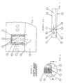
- Figure 1 is the guidance system of air flows within the aircraft door area shown in the front view.
- the detail A illustrated in FIG 1 shows an air duct with which the targeted derivation of air flows from the Aircraft door area is operated.
- the section A - A, which extracts the 1 shows a plan view of the part of the aircraft door area near the ground according to FIG. 1, illustrates the part sinking behind the door frame lining of the aircraft door cooled air that flows into an air duct integrated in the door frame.
- the air flow guidance system is composed as follows.
- the guidance system definitely refers to a door area of the aircraft, which is located above the floor structure 5, which covers the underfloor area 9 of the fuselage.
- the area of the aircraft door area is integrated (inside) in terms of area from the door frame 2 and an aircraft door 3 received by it, which lines the aircraft fuselage.
- the door frame 2 is positively fitted to a door cutout that is excluded from the aircraft fuselage structure 1.
- the door frame 2 the supporting structure of which spans an open part of the door, takes in this section - positively fitted - an aircraft door 3, the curved shape of the fuselage follows, which - on (with) the supporting structure (one of the two door frame stands) attached (locked) - according to example (in unlocked state) can be pivoted outside the fuselage.
- FIG. 3 An anticipation of FIG. 3 completes that the aircraft door 3 is built up from several layers. It consists of a door structure 3.1, which has an (outer) paneling 3.2 and an (inner) door panel 3.3 firmly attached. In terms of air flow technology, the door structure 3.1 is interspersed with cavities that lie specifically between individual (not shown) door elements for mechanical, pneumatic or electrical operation (control or actuation) of the aircraft door, these door elements also being part of the door structure 3.1.
- the planking 3.2 and the door trim 3.3 cover the edge of the door structure 3.1, so that between the supporting structure of the door frame 2 and the door structure 3.1 there is a door gap 7 [gap-like (channel-like) opening, the cross section of which is due to the edge-side distance between the door structure 3.1 and the Door frame 2 on the one hand and between the planking 3.2 and the door trim 3.3 on the other hand is determined.
- an interior trim seal 4.1 (as the first sealing element) is strip-shaped and along the edge along the inner surface (facing the open door section) of the door frame 2 (the door frame support structure) attached to against the opposite Side edges of the door trim 3.3 of the closed aircraft door 3 tight.
- a door seal 4.2 (as a second sealing element) is strip-shaped and on the edge attached along the inner surface of the outer paneling 3.2 to against the outside the plane directed side surface of the door frame 2 of the closed Seal aircraft door 3.
- the upper edge area of the door trim 3.3 has a trim column 6, which lie above the cross-sectional area of the door gap 7 which is guided below.
- the the cross-section of the door gaps 7 that is encircled at the edges of the door structure 3.1 is, as previously indicated - and clearly recognizable from Fig. 3 - through the door trim 3.3 with respect to the interior of the fuselage structure of the aircraft using the first interior trim seal 4.1 (when the aircraft door 3 is closed) foreclosed.
- FIG. 2 shows detail A of the aircraft door area according to FIG. 1 with a special representation an air duct 8, which leads to the underfloor region 9 of the aircraft, shown. It is in the cross section of the door frame 2 (left and right of the Door frame stand).
- the side edge areas of the door structure 3.1 (aforementioned) bordered door air outlet opening (s) 10 are also in this illustration indicated.
- FIG. 3 shows the section A - A of the aircraft door area according to FIG. 1, which corresponds to that described above Structure of the aircraft door area and the integrated position of the air duct 8 illustrated in the door frame 2 (for example according to Fig.2).
- the Air duct 8 through the cross section of the door frame support structure (the Door frame stand). It opens sideways near and above the floor structure 5 of the door frame 2 in the door column 7. Below the floor structure 5 it is in the Underfloor area 9 out.
- the air duct 8 is tubular in practice. It has a right-angled one Form, wherein the inlet part of the air duct 8 opening into the door gap 7 runs almost parallel to the fuselage longitudinal axis of the aircraft, which follows it Right-angled bend connects the downstream outlet part, which is in the underfloor area 9 is performed.
- the door frame 2 for example additionally clad with a right-angled door frame trim 2.1 can be. According to this version, it is against the side edge of the door trim 3.3 sealing interior trim seal 4.1 above the door frame trim 2.1, along the (facing the open door section) inner surface of the Door frame 2 (the door frame support structure) is attached.
- the cladding column 6 warm cabin or cockpit air run behind the panels. This divides the inner area of the Aircraft fuselage (cabin or cockpit area) extracted air flow in two partial air flows (left / right), which then flow to the air duct inlet of the air duct 8 and via the air duct outlet of the air duct 8 into the underfloor region 9 of the fuselage be directed. This measure ensures that - without additional Introduction of thermal energy into the aircraft door area - the surface temperatures significantly increased on an airplane door.
- the warm cabin sections which are guided in part by the channel-like cross section of the door column 7, or cockpit air also prevents the door surface from cooling down, because the warm air acting on the edge area of the door structure 3.1 is the surface temperature the aircraft door 3 stabilized and the unfavorable influence of cold air flow prevented (due to the temperature difference mentioned) in this (edge) section.
- An "air drain channel formed with the channel-like cross section of the door column 7 "has no negative influence on the heat loads within the fuselage structure out.
- the thermal conditions of the door areas of the aircraft for passengers sitting near an aircraft door can be influenced favorably without the Use of additional heat sources, for example the installation of a heated floor plate in the aircraft door area.
- the solution avoids the use of additional energy (of different types, for example electrical or pneumatic Energy), resulting in the existing total energy potential of the aircraft remains unchanged.
- additional energy of different types, for example electrical or pneumatic Energy
- the implementation of the measure closes the use mechanically stressed parts, which means no increase in maintenance entry.
- the measure also helps to save costs, since the installation is more complex local measuring points in the aircraft door area and the subordinate to them Control and regulating devices can be dispensed with, so that the (only by means of additionally installed heating device technology) achieved improved thermal conditions secure.
Landscapes
- Engineering & Computer Science (AREA)
- Mechanical Engineering (AREA)
- Aviation & Aerospace Engineering (AREA)
- Specific Sealing Or Ventilating Devices For Doors And Windows (AREA)
- Ventilation (AREA)
- Building Environments (AREA)
- Buildings Adapted To Withstand Abnormal External Influences (AREA)
Claims (4)
- Porte d'aéronef avec système de guidage pour écoulement d'air déterminé par un châssis de porte (2) inséré avec adhérence dans la zone d'une section de porte d'une structure de fuselage d'avion (1), au-dessus d'une structure de plancher (5) recouvrant la zone de sous-plancher (9) aérée d'un aéronef, par une porte d'avion (3) disposée à l'intérieur d'une zone partielle de porte ouverte délimitée par le châssis de porte et capable de pivoter vers l'extérieur du fuselage d'aéronef, la porte d'aéronef (3) présentant une structure de porte (3.1) avec bordé extérieur (3.2) fermement appliqué et revêtement de porte intérieur (33) ayant été isolée de l'environnement extérieur et intérieur, en position entièrement fermée et verrouillée contre le châssis de porte, par l'intermédiaire d'éléments de joint (4) reposant avec adhérence entre le bordé et le revêtement (2), la structure de porte (3.1) ayant été traversée par des espaces creux perforés à l'aide de techniques d'écoulement d'air, une fissure de revêtement destinée à la ventilation forcée étant située au-dessus du revêtement de porte, ladite fente étant aérée partiellement par les espaces creux de la structure de porte (3.1),
caractérisée en ce qu'une fente de porte (7) est cloisonnée entre la structure de porte (3.1) et le châssis de porte (2), lorsque la porte d'aéronef (3) est fermée. La section transversale de ladite fente est déterminée par l'écartement marginal entre, d'une part, la structure de porte (3.1) et le châssis de porte (2) et d'autre part le bordé (3.2) et le revêtement de porte (3.3) procédant au transport d'une autre partie de l'air aéré via une fente de revêtement (6), en ce qu'un canal d'air (8) inséré dans le châssis de porte (2) a été dérivé afin de dévier l'air transporté à travers la fente de porte (7) et les espaces creux de la structure de porte (3.1), ledit canal d'air débouchant dans la fente de porte (7), près de et au-dessus de la structure de plancher (5), latéralement par rapport au châssis de porte (2) et ayant été guidé dans la zone de sous-plancher (9), sous la structure de plancher. - Porte d'aéronef selon la revendication 1, caractérisée en ce que les éléments de jointoiement sont lamelliformes, un premier élément de jointoiement exécuté sous la forme d'un joint de revêtement interne (4.1) ayant été fixé sous la forme d'une lamelle et marginalement le long de la surface interne du châssis de porte (2), afin de jointoyer contre les bords latéraux du revêtement (3.3) de la porte d'aéronef (3) fermée, et un deuxième élément de jointoiement exécuté sous la forme d'un joint de porte (4.2) ayant été fixé sous la forme de lamelles et marginalement le long de la surface interne du bordé externe (3.1), pour jointoyer contre la surface latérale du châssis (2) de la porte d'aéronef (3) fermée orientée vers l'extérieur de l'avion, de telle sorte que l'entrée du canal d'air (8) débouchant dans la fente de porte (7) soit disposée avec des techniques d'écoulement d'air entre le joint du revêtement de porte (4.1) et le joint de la porte (4.2).
- Porte d'aéronef selon la revendication 1, caractérisée en ce que le canal d'air (8) a une forme voûtée rectangulaire, la composante d'admission du canal d'air (8) débouchant dans la fente de porte (7) couvrant l'étendue presque parallèle de l'axe longitudinal du fuselage de l'aéronef, la composante d'évacuation du canal d'air (8) disposée perpendiculairement en aval et guidée dans la zone de sous-plancher (9) joignant la composante d'admission.
- Porte d'aéronef selon la revendication 1, caractérisée en ce que le châssis de porte (2) a été recouverte d'un revêtement de châssis de porte à angle perpendiculaire vers le bas (2.1), et en ce que le joint de revêtement intérieur (4.1) fermant contre le revêtement de porte (3.3) a été disposé au-dessus de la zone du revêtement du châssis de porte (2.1) fixée sur la face interne du châssis de porte (2).
Applications Claiming Priority (2)
| Application Number | Priority Date | Filing Date | Title |
|---|---|---|---|
| DE19640741A DE19640741C2 (de) | 1996-10-02 | 1996-10-02 | Führungssystem von Luftströmen innerhalb eines Flugzeugtürbereiches |
| DE19640741 | 1996-10-02 |
Publications (3)
| Publication Number | Publication Date |
|---|---|
| EP0834452A2 EP0834452A2 (fr) | 1998-04-08 |
| EP0834452A3 EP0834452A3 (fr) | 1999-06-23 |
| EP0834452B1 true EP0834452B1 (fr) | 2004-08-04 |
Family
ID=7807735
Family Applications (1)
| Application Number | Title | Priority Date | Filing Date |
|---|---|---|---|
| EP97116887A Expired - Lifetime EP0834452B1 (fr) | 1996-10-02 | 1997-09-29 | Porte d'aéronef avec un système di guidage pour écoulement d'air |
Country Status (4)
| Country | Link |
|---|---|
| US (1) | US6019315A (fr) |
| EP (1) | EP0834452B1 (fr) |
| DE (2) | DE19640741C2 (fr) |
| ES (1) | ES2225922T3 (fr) |
Families Citing this family (7)
| Publication number | Priority date | Publication date | Assignee | Title |
|---|---|---|---|---|
| US6454210B1 (en) * | 2000-07-13 | 2002-09-24 | Wesley M. Plattner | Aircraft vent and cargo door locking mechanism |
| DE10035349C1 (de) * | 2000-07-20 | 2001-09-27 | Eurocopter Deutschland | Flugzeugtür |
| DE10361655B4 (de) * | 2003-12-30 | 2007-10-04 | Airbus Deutschland Gmbh | Vorrichtung und Verfahren zur Fußbodenheizung in einem Flugzeug |
| EP1773664B1 (fr) * | 2004-08-03 | 2013-11-06 | Airbus | Porte destinee a fermer une ouverture a l'interieur d'un aeronef |
| US9505498B2 (en) * | 2007-08-31 | 2016-11-29 | The Boeing Company | Aircraft cabin airflow nozzles and associated systems and methods |
| FR2975966B1 (fr) * | 2011-05-31 | 2013-06-14 | Latecoere | Aeronef comportant une cabine delimitee par un fuselage dote d'au moins une ouverture d'acces a la dite cabine, et un dispositif d'obturation de la dite ouverture. |
| EP2712806B1 (fr) * | 2012-09-28 | 2016-05-11 | Airbus Operations GmbH | Une partition pour véhicule |
Family Cites Families (11)
| Publication number | Priority date | Publication date | Assignee | Title |
|---|---|---|---|---|
| US376827A (en) * | 1888-01-24 | Michael a | ||
| US691260A (en) * | 1901-05-16 | 1902-01-14 | Ernest A Giesser | Ventilating-window. |
| US1674535A (en) * | 1924-07-12 | 1928-06-19 | Alfred V Verville | Ventilating system |
| US2058659A (en) * | 1931-06-12 | 1936-10-27 | Giuseppe M Bellanca | Ventilation of airplanes |
| FR1328853A (fr) * | 1962-07-16 | 1963-05-31 | Vickers Armstrongs Aircraft | Perfectionnements aux portes |
| FR1406512A (fr) * | 1964-05-06 | 1965-07-23 | Maille & Vagneux Ets | Procédé et dispositif pour éviter le givrage des joints d'étanchéité de portes d'enceintes réfrigérées |
| GB2192451B (en) * | 1986-05-21 | 1990-07-04 | Paul Whyatt | Thermal transfer door |
| US4854010A (en) * | 1987-11-20 | 1989-08-08 | The Boeing Company | Hinge mechanism for aircraft door |
| DE3802583A1 (de) * | 1988-01-29 | 1989-08-10 | Wetzel Alfred | Lueftungsvorrichtung fuer fenster und/oder fenstertueren zur rekuperativen be- und entlueftung von aufenthaltsraeumen |
| US5064147A (en) * | 1990-02-12 | 1991-11-12 | The Boeing Company | Upwardly opening plug-type door for use as an over-wing emergency hatch |
| US5398889A (en) * | 1994-02-22 | 1995-03-21 | Furon Company | Aircraft fuselage lining system |
-
1996
- 1996-10-02 DE DE19640741A patent/DE19640741C2/de not_active Expired - Fee Related
-
1997
- 1997-09-29 ES ES97116887T patent/ES2225922T3/es not_active Expired - Lifetime
- 1997-09-29 DE DE59711824T patent/DE59711824D1/de not_active Expired - Lifetime
- 1997-09-29 EP EP97116887A patent/EP0834452B1/fr not_active Expired - Lifetime
- 1997-10-02 US US08/942,591 patent/US6019315A/en not_active Expired - Fee Related
Also Published As
| Publication number | Publication date |
|---|---|
| DE19640741C2 (de) | 1998-07-23 |
| DE19640741A1 (de) | 1998-04-23 |
| EP0834452A3 (fr) | 1999-06-23 |
| DE59711824D1 (de) | 2004-09-09 |
| US6019315A (en) | 2000-02-01 |
| EP0834452A2 (fr) | 1998-04-08 |
| ES2225922T3 (es) | 2005-03-16 |
Similar Documents
| Publication | Publication Date | Title |
|---|---|---|
| DE4408493C1 (de) | Vorrichtung zur Abwasserdrainage aus Flugzeugen | |
| DE3686220T2 (de) | Wiederverwendbare thermische schutzelemente fuer ein stark geheiztes objekt. | |
| EP0834452B1 (fr) | Porte d'aéronef avec un système di guidage pour écoulement d'air | |
| EP0846615B1 (fr) | Ensemble de fenêtre pour cabine d'aéronef | |
| WO2005012083A1 (fr) | Pont a fret et son procede de montage | |
| DE102011082888A1 (de) | Auftriebsklappenlagervorrichtung, Auftriebsklappenanordnung, Tragflügel sowie Flugzeug | |
| DE19921326C1 (de) | Rinnenprofil zur Ableitung von Flüssigkeit | |
| EP2268542A2 (fr) | Système universel pour maintenir un rail de rideau pour un rideau de séparation | |
| DE19728265C2 (de) | Vorrichtung zur Belüftung eines Aggregates an einem Fahrzeug | |
| DE10223840A1 (de) | Kanal-Anordnung | |
| DE19501593C2 (de) | Heizungs- und Belüftungsvorrichtung für den Fahrgastraum eines Kraftfahrzeuges | |
| EP2384300B1 (fr) | Procede et dispositif de degivrage exterieur d'aeronefs | |
| DE102009003937A1 (de) | Flugzeugklimaanlage mit einer verringerten Vereisungsgefahr | |
| EP3964761A1 (fr) | Procédé de dégivrage d'un composant exposé à l'air ambiant et dispositifs de mise en uvre du procédé | |
| DE102007062528B4 (de) | Türflügel für ein Fahrzeug | |
| EP2780529B1 (fr) | Appareil de ventilation pour le dormant profilé d'un battant, et procédé d'échange d'air au niveau d'une fenêtre | |
| DE19918906C2 (de) | PTC-Heizregister | |
| DE102005043898A1 (de) | Fenster-Anordnung zum Einrichten größerer Flugzeugfenster | |
| DE102014201109A1 (de) | Fahrzeug, insbesondere Schienenfahrzeug, mit Wagenkasten und Fußboden | |
| DE102018129183A1 (de) | Kabinenmodul mit integrierter Drainage und Flugzeug mit Kabinenmodul | |
| DE202004015698U1 (de) | Hitzeschild | |
| DE2757651B2 (de) | Heiz- und Belüftungsvorrichtung | |
| DE102018202131B4 (de) | Komponente für ein Kraftfahrzeug und Kraftfahrzeug | |
| EP0936138A2 (fr) | Fenêtre à double vitrage pour la cabine d'un aéronef | |
| DE29704709U1 (de) | Heizungsgerät |
Legal Events
| Date | Code | Title | Description |
|---|---|---|---|
| PUAI | Public reference made under article 153(3) epc to a published international application that has entered the european phase |
Free format text: ORIGINAL CODE: 0009012 |
|
| AK | Designated contracting states |
Kind code of ref document: A2 Designated state(s): DE ES FR GB IT |
|
| RAP3 | Party data changed (applicant data changed or rights of an application transferred) |
Owner name: DAIMLERCHRYSLER AEROSPACE AIRBUS GESELLSCHAFT MIT |
|
| PUAL | Search report despatched |
Free format text: ORIGINAL CODE: 0009013 |
|
| AK | Designated contracting states |
Kind code of ref document: A3 Designated state(s): AT BE CH DE DK ES FI FR GB GR IE IT LI LU MC NL PT SE |
|
| RIC1 | Information provided on ipc code assigned before grant |
Free format text: 6B 64C 1/14 A, 6B 64C 1/40 B, 6B 64D 13/00 B |
|
| 17P | Request for examination filed |
Effective date: 19990531 |
|
| AKX | Designation fees paid |
Free format text: DE ES FR GB IT |
|
| RAP1 | Party data changed (applicant data changed or rights of an application transferred) |
Owner name: EADS AIRBUS GMBH |
|
| RAP1 | Party data changed (applicant data changed or rights of an application transferred) |
Owner name: AIRBUS DEUTSCHLAND GMBH |
|
| GRAP | Despatch of communication of intention to grant a patent |
Free format text: ORIGINAL CODE: EPIDOSNIGR1 |
|
| RTI1 | Title (correction) |
Free format text: AIRCRAFT DOOR WITH GUIDING SYSTEM FOR AIR FLOW |
|
| RTI1 | Title (correction) |
Free format text: AIRCRAFT DOOR WITH GUIDING SYSTEM FOR AIR FLOW |
|
| GRAS | Grant fee paid |
Free format text: ORIGINAL CODE: EPIDOSNIGR3 |
|
| GRAA | (expected) grant |
Free format text: ORIGINAL CODE: 0009210 |
|
| AK | Designated contracting states |
Kind code of ref document: B1 Designated state(s): DE ES FR GB IT |
|
| REG | Reference to a national code |
Ref country code: GB Ref legal event code: FG4D Free format text: NOT ENGLISH |
|
| REF | Corresponds to: |
Ref document number: 59711824 Country of ref document: DE Date of ref document: 20040909 Kind code of ref document: P |
|
| GBT | Gb: translation of ep patent filed (gb section 77(6)(a)/1977) |
Effective date: 20041112 |
|
| REG | Reference to a national code |
Ref country code: ES Ref legal event code: FG2A Ref document number: 2225922 Country of ref document: ES Kind code of ref document: T3 |
|
| PLBE | No opposition filed within time limit |
Free format text: ORIGINAL CODE: 0009261 |
|
| STAA | Information on the status of an ep patent application or granted ep patent |
Free format text: STATUS: NO OPPOSITION FILED WITHIN TIME LIMIT |
|
| ET | Fr: translation filed | ||
| 26N | No opposition filed |
Effective date: 20050506 |
|
| PGFP | Annual fee paid to national office [announced via postgrant information from national office to epo] |
Ref country code: ES Payment date: 20100924 Year of fee payment: 14 |
|
| PGFP | Annual fee paid to national office [announced via postgrant information from national office to epo] |
Ref country code: FR Payment date: 20101005 Year of fee payment: 14 |
|
| PGFP | Annual fee paid to national office [announced via postgrant information from national office to epo] |
Ref country code: GB Payment date: 20100921 Year of fee payment: 14 |
|
| PGFP | Annual fee paid to national office [announced via postgrant information from national office to epo] |
Ref country code: IT Payment date: 20100927 Year of fee payment: 14 |
|
| REG | Reference to a national code |
Ref country code: ES Ref legal event code: PC2A Owner name: AIRBUS OPERATIONS GMBH Effective date: 20110930 |
|
| PGFP | Annual fee paid to national office [announced via postgrant information from national office to epo] |
Ref country code: DE Payment date: 20110930 Year of fee payment: 15 |
|
| REG | Reference to a national code |
Ref country code: FR Ref legal event code: CD Owner name: AIRBUS OPERATIONS GMBH Effective date: 20111118 |
|
| GBPC | Gb: european patent ceased through non-payment of renewal fee |
Effective date: 20110929 |
|
| PG25 | Lapsed in a contracting state [announced via postgrant information from national office to epo] |
Ref country code: IT Free format text: LAPSE BECAUSE OF NON-PAYMENT OF DUE FEES Effective date: 20110929 |
|
| REG | Reference to a national code |
Ref country code: FR Ref legal event code: ST Effective date: 20120531 |
|
| PG25 | Lapsed in a contracting state [announced via postgrant information from national office to epo] |
Ref country code: FR Free format text: LAPSE BECAUSE OF NON-PAYMENT OF DUE FEES Effective date: 20110930 Ref country code: GB Free format text: LAPSE BECAUSE OF NON-PAYMENT OF DUE FEES Effective date: 20110929 |
|
| REG | Reference to a national code |
Ref country code: ES Ref legal event code: FD2A Effective date: 20130605 |
|
| PG25 | Lapsed in a contracting state [announced via postgrant information from national office to epo] |
Ref country code: ES Free format text: LAPSE BECAUSE OF NON-PAYMENT OF DUE FEES Effective date: 20110930 Ref country code: DE Free format text: LAPSE BECAUSE OF NON-PAYMENT OF DUE FEES Effective date: 20130403 |
|
| REG | Reference to a national code |
Ref country code: DE Ref legal event code: R119 Ref document number: 59711824 Country of ref document: DE Effective date: 20130403 |