EP0834458A1 - Dispositif à commande par calculateur pour la préparation de commandes d'articles souples - Google Patents
Dispositif à commande par calculateur pour la préparation de commandes d'articles souples Download PDFInfo
- Publication number
- EP0834458A1 EP0834458A1 EP97115400A EP97115400A EP0834458A1 EP 0834458 A1 EP0834458 A1 EP 0834458A1 EP 97115400 A EP97115400 A EP 97115400A EP 97115400 A EP97115400 A EP 97115400A EP 0834458 A1 EP0834458 A1 EP 0834458A1
- Authority
- EP
- European Patent Office
- Prior art keywords
- picking device
- article
- output means
- guide
- gripper
- Prior art date
- Legal status (The legal status is an assumption and is not a legal conclusion. Google has not performed a legal analysis and makes no representation as to the accuracy of the status listed.)
- Granted
Links
- 239000000853 adhesive Substances 0.000 claims abstract description 5
- 230000001070 adhesive effect Effects 0.000 claims abstract description 5
- 230000004888 barrier function Effects 0.000 claims description 3
- 230000003287 optical effect Effects 0.000 claims description 3
- 238000001514 detection method Methods 0.000 claims description 2
- 238000010586 diagram Methods 0.000 description 8
- 230000007246 mechanism Effects 0.000 description 6
- 230000000694 effects Effects 0.000 description 3
- 238000000926 separation method Methods 0.000 description 3
- 238000000034 method Methods 0.000 description 2
- 230000008569 process Effects 0.000 description 2
- 238000012549 training Methods 0.000 description 2
- 238000013459 approach Methods 0.000 description 1
- 230000008859 change Effects 0.000 description 1
- 239000011888 foil Substances 0.000 description 1
- 238000004806 packaging method and process Methods 0.000 description 1
- 238000012856 packing Methods 0.000 description 1
- 230000002441 reversible effect Effects 0.000 description 1
- 125000006850 spacer group Chemical group 0.000 description 1
- 230000032258 transport Effects 0.000 description 1
Images


Classifications
-
- B—PERFORMING OPERATIONS; TRANSPORTING
- B65—CONVEYING; PACKING; STORING; HANDLING THIN OR FILAMENTARY MATERIAL
- B65G—TRANSPORT OR STORAGE DEVICES, e.g. CONVEYORS FOR LOADING OR TIPPING, SHOP CONVEYOR SYSTEMS OR PNEUMATIC TUBE CONVEYORS
- B65G1/00—Storing articles, individually or in orderly arrangement, in warehouses or magazines
- B65G1/02—Storage devices
- B65G1/04—Storage devices mechanical
- B65G1/0407—Storage devices mechanical using stacker cranes
Definitions
- the invention relates to a computer-controlled picking device for Order picking of soft goods with a motorized conveyor belt and several, at least on one side of the conveyor belt next to and / or superposed recordings for recording the items to be picked stackable soft good items using a computer-controlled Output means on the conveyor belt that transports the articles be delivered.
- Such a picking device is known from DE 41 26 554 A1.
- the output means used here is a shaft-like one at the end of the articles Recording arranged conveyor belt used on which each lowest article on which the following are stacked. this article is sucked in by vacuum and then removed.
- the picking device is disadvantageous in several ways. Because on the one hand rests on the lowest article to be pulled off the conveyor belt the weight of the article column, which makes it difficult to separate. Heavy articles become not taken at all by the vacuum nozzle. Another disadvantage is that the articles must inevitably be sealed in foil so that the the suction based article principle works at all. Further it can happen that the bottom article is more or less on top of it firmly adheres, which leads to the fact that the one above when the lower part is taken away. Although this is over an overlying one Stop plate prevented from triggering, but in any case it does not lie more so ready that it could be easily removed.
- the invention is therefore based on the problem of a commissioning device indicate which is a simple and safe removal of the article from the Allows recording.
- the picking device is at the beginning mentioned type provided according to the invention that the output means as a movable, detachably engaging on the top of the article in the holder, this is designed to remove and deliver towards the conveyor belt is.
- the article is therefore removed from above, i.e. it is only to move the weight of the article itself, but not against the complete one Weight of the article column to work.
- the article can thus advantageously be essential be separated more easily than was the case in the prior art.
- the output means is like a pair of pliers Gripper is designed as a suction means or as an adhesive adhesive, wherein especially the gripper, which grips and clamps the article directly, as Has proven expedient, since it can be removed from both, for example foil-welded articles, such as shirts or the like, as well as unpacked articles, for example with a banderole or the like. held together are, can be used, because due to the direct, the article or the packaging jamming attack is in any case a safe one Packing and removal possible.
- the dispensing means between the position attacking the article and the position relinquishing the article along an arc or curve-shaped, allowing a minimum stroke of the article Web is guided.
- This arcuate or curved guide which is essentially the attack process corresponds to how it would be done manually advantageous a minimum stroke, which ultimately allows the gripped First raise the article a short distance, then only the actual translational Begin movement, taking the arc or curved path of course not over the entire movement distance between the two defined positions, but only within a sub-area of which can be realized, which then expediently itself connects to the attack position.
- the output means can also along a substantially straight line, possibly inclined to the horizontal Can be guided.
- the output means at least when it is positioned above the item to be removed, along a substantially straight, substantially vertical Web is guided in this way to a larger vertical, the singulation serving hub.
- the output means at least one sensor element for detecting the positional relationship of the Output means is assigned to the above article, the operation of the Output means depending on the detection result.
- the sensor element as arranged on the output means Push button switch is designed to be necessary for controlling the operation Signal when there is sufficient positioning to enable intervention on the article is given, preferably two key switches are provided. Alike However, optical or mechanical sensor elements can also be used.
- the dispensing means can be movable via a motor-driven guide device, which can be a chain, a cable or a belt, on which the output means, preferably via an intermediate, in particular rod-shaped Bracket is arranged.
- a motor-driven guide device which can be a chain, a cable or a belt, on which the output means, preferably via an intermediate, in particular rod-shaped Bracket is arranged.
- the guide device has a rod-like, rotatable or pivotable guide arm is along which the output means, possibly movable and preferably over an intermediate, in particular rod-like holder is arranged.
- Both alternative designs enable the dispensing means to be guided safely, for example the gripper, in the direction of the article as well as in the direction the conveyor belt on which the article is then to be delivered. Training too in the form of a rotatable or swivel-mounted rocker, along which the Output means e.g. run on roles by his own weight and running accordingly is possible to adjust the respective
- the invention provide that the guide device on a the recording-limiting side wall or the like. is arranged on the outside, wherein the side wall has an opening through which the Output means or the holder that engages inside the receptacle.
- This configuration is also expedient than due to the outside Arrangement a striking the article on the guide device or damage to the articles by the latter is excluded.
- the opening essentially corresponds to the path of movement of the dispensing means, possibly the holder, and who, if necessary using a sliding block or the like, guiding the dispensing means, possibly the bracket is used, so that in this way in addition to the leadership by means of Guide device an additional guidance and storage is realized.
- the Output means can also be slidably mounted on the holder, to that effect is advantageous when the recordings in practice are not a specific one Item sizes are assigned, rather are often processed after a batch of items introduced other, different sized items, so that it with the displaceable storage according to the invention is possible, the output means to be positioned on the holder so that, for example in the case of the gripper, he can attack exactly on the respective article.
- the guide device as extending horizontally or vertically along several recordings Guide rail or the like is formed, on which at least one Gripper along the receptacles, reversible on these for removing the article is positioned, moved, the guide rail and / or the Gripper, possibly by means of a guide arm pivotably mounted on the guide rail, movable to allow access to the recordings, is particularly pivotable.
- This especially for medium and slow moving devices suitable execution does not see a means of output for every image before, rather this - or more - along the recordings a suitable guide rail or the like.
- movable and can if necessary before respective recording containing the desired article so that the medium and slow-moving devices mentioned accordingly can be designed less complex.
- the guidance of the dispensing means according to the invention is distinguished characterized in that primarily at the beginning of the removal process Mindeshub is realized, which enables a safe separation.
- the receptacle carries the article by means of a lifting device Motorized height-adjustable bottom part, so that the article accordingly are trackable, but at the same time there is also the possibility of appropriate Control the bottom part after the dispensing device has attacked the article lower briefly, and thus effect the separation process.
- the bottom part with the lifting device preferably as a polygonal Rod-shaped bracket can be connected, in particular a polygonal Rod a twisting of the bottom part, for example due to a one-sided loading, safely prevented.
- the side walls delimiting the receptacle is designed to be displaceable, for example into corresponding grooves that can be inserted into the supporting frame of the device or the like. usable and screwable or the like. is.
- at least one sensor element in particular an optical sensor element for detecting the fill level of the receptacle is provided is, for which light barriers or the like. are appropriate, equally but also mechanical means such as a button switch embedded in the bottom or the like.
- a slide inclined towards the conveyor belt be on which the respective article is given, in which in further Execution of a sensor device, in particular a light barrier for Counting of the items given on the slide is integrated. It can also be provided be that on the slide in the area towards the recording, a distance insert is releasably attachable, by means of which a change in the article size resulting gap is closed and for a front guide and bracket the article is taken care of, so that even tipping forward for smaller ones Articles is excluded.
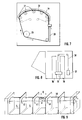
- FIG. 1 shows a front view of the picking device. This exists from a support frame 1, in which by means of movable side walls 2 and fixed arranged walls 3 which carry the dispensing means and which correspond to the dispensing means Article receiving receptacles 4 are formed.
- the sidewalls 2 can be inserted into grooves formed on the support frame 1 accordingly and displaceable and can with suitable means, such as screws, be attached in this way to corresponding changing article sizes to be able to react.
- Different sized images are in Fig. 1 in shown on the bottom line.
- Each recording is an output means 5 assigned, here in the form of a gripper.
- the Gripper can be pivoted via a swivel mechanism 6, as by the double arrow A is indicated.
- Embodiment includes the swivel mechanism a swivel arm, which will be described in the following.
- FIG. 3 The possible with the known from Fig. 2 swivel mechanism guidance of The gripper is shown in the form of a schematic diagram in FIG. 3.
- a gripper is shown 8, which reciprocates along the arcuate path 9 by means of the swivel mechanism can be moved, cf. Double arrow B.
- the articles 10 are so far upwards by means of the bottom part promoted until the gripper 8 can attack the overhead.
- the Gripper 8 has gripped the article 11, this is with the swivel mechanism moves along the arcuate path 9, causing the gripped article is raised and thus separated.
- the gripper 9 becomes arcuate to the end Track, where he hands the gripped article on a slide 12, see. the left end position in FIG. 3.
- the slide 12 is a sensor element 13 assigned to count the number of items.
- Fig. 3 also shows one on the slide 12 releasably attachable spacer insert 14, which is used to a front To ensure the guidance of the articles and to prevent them from tipping over, if these are so small that they do not protrude to the front of the slide 12 and from this can be done. 3 shows, is with such arcuate guideway a safe separation as a result of the beginning the removal movement possible stroke. After removal One part of the bottom part 10 is tracked until the next article is positioned again in the area of the gripper 8.
- FIG. 4 An alternative embodiment is shown in Fig. 4.
- the gripper 8 is along one in move essentially horizontal path 15.
- the bottom part 10 is again Height adjustable. The removal takes place here such that the bottom part so far up until the gripper 8 the article above takes hold. Then the bottom part moves down a short distance until the seized article is isolated. After this, the gripper 8 is in the left position brought, in which the gripped article is given.
- Fig. 5 shows a concrete embodiment of a swivel mechanism in the form of a Principle sketch.
- a swivel arm arranged on a side wall 3 is shown 16, which is pivotable about a fixed axis of rotation 17.
- the bracket 18 occurs through the side wall in an opening 19, which at the same time the Leadership serves.
- the guide is essentially arched in the upper area educated.
- the bracket 18 may be fixed to the swivel arm 16, wherein the guidance is such and the swivel arm 16 is arranged and mounted in this way is that the arcuate trajectory shown in Fig.
- the opening is in this described solution 19 guided vertically in the area 20.
- the bracket is 18th slidably supported on the swivel arm 16, which enables them to predetermined by the opening 19, moves it along this. So that's it possible to lower the gripper deep into the holder, and also lower ones To be able to grab articles.
- the height can be adjusted Lifting part can be dispensed with, since the gripper itself extends deep into the holder can be retracted.
- FIGS. 5, 6 An alternative embodiment to the swivel arm described in FIGS. 5, 6 shows Fig. 7.
- 7 shows the guide of the chain for the case that the opening 19 has a vertical region 20. Is specified but also a guide for the case that is essentially a removal movement corresponds as described in Fig. 3 (dashed chain guide). In this In this case, it is not necessary to guide the chain to the lower edge of the side wall.
- Fig. 8 shows a schematic diagram of the outside of a recording Side wall and the lifting device for the plate-like carrying the article Bottom part. This is, via a holder, not shown, on a carriage 35 arranged, or the like via rollers. on two rails 36, which in the area of Side wall are arranged, is guided. To move it is the sled connected via a traction cable 38 to an actuating device 37, so that space-saving A sufficient stroke is possible.
Landscapes
- Engineering & Computer Science (AREA)
- Mechanical Engineering (AREA)
- De-Stacking Of Articles (AREA)
- Manipulator (AREA)
- Specific Conveyance Elements (AREA)
Applications Claiming Priority (2)
| Application Number | Priority Date | Filing Date | Title |
|---|---|---|---|
| DE19639049A DE19639049B4 (de) | 1996-09-24 | 1996-09-24 | Rechnergesteuerte Kommissioniervorrichtung zum Kommissionieren von Softgood-Artikeln |
| DE19639049 | 1996-09-24 |
Publications (2)
| Publication Number | Publication Date |
|---|---|
| EP0834458A1 true EP0834458A1 (fr) | 1998-04-08 |
| EP0834458B1 EP0834458B1 (fr) | 2004-03-17 |
Family
ID=7806641
Family Applications (1)
| Application Number | Title | Priority Date | Filing Date |
|---|---|---|---|
| EP97115400A Expired - Lifetime EP0834458B1 (fr) | 1996-09-24 | 1997-09-05 | Dispositif à commande par calculateur pour la préparation de commandes d'articles souples |
Country Status (3)
| Country | Link |
|---|---|
| EP (1) | EP0834458B1 (fr) |
| AT (1) | ATE261886T1 (fr) |
| DE (2) | DE19639049B4 (fr) |
Families Citing this family (3)
| Publication number | Priority date | Publication date | Assignee | Title |
|---|---|---|---|---|
| EP0941951A1 (fr) | 1998-03-10 | 1999-09-15 | Quelle Schickedanz AG & Co. | Dispositif de préhension du style pince |
| DE10005480A1 (de) * | 2000-02-08 | 2001-08-16 | Quelle Ag | Kommissioniervorrichtung zum Kommissionieren von Artikeln, insbesondere von Softgoodartikeln |
| CN118760000B (zh) * | 2024-08-07 | 2025-07-22 | 四川弘智远大科技有限公司 | 一种数据机房设备运行监控系统及方法 |
Citations (4)
| Publication number | Priority date | Publication date | Assignee | Title |
|---|---|---|---|---|
| FR2126265A1 (fr) * | 1971-02-22 | 1972-10-06 | Eaton Corp | |
| DE4126554A1 (de) * | 1991-08-10 | 1993-02-11 | Electrocom Automation Gmbh | Verfahren und vorrichtung zur aufnahme und programmsteuerbaren automatischen abgabe von waren |
| DE4338407C1 (de) * | 1993-11-10 | 1995-04-27 | Quelle Schickedanz Ag & Co | Verfahren zum Erkennen und Versenden von Artikeln aus Retouren für Single-Bestellungen, insbesondere von Bekleidungsstücken |
| EP0802128A2 (fr) * | 1996-04-19 | 1997-10-22 | P.E.E.M. Förderanlagen Ges.m.b.H. | Installation de préparation de commandes |
Family Cites Families (5)
| Publication number | Priority date | Publication date | Assignee | Title |
|---|---|---|---|---|
| US3770140A (en) * | 1969-09-25 | 1973-11-06 | American Ass Cybernetics | Sensor responsive cybernetics machine |
| DE3733461A1 (de) * | 1987-09-30 | 1989-04-20 | Kht Kommissionier & Handhabung | Verfahren und vorrichtung zum entnehmen von buechern oder dergleichen aus einem regal |
| DE3941754A1 (de) * | 1989-12-18 | 1991-06-20 | Fraunhofer Ges Forschung | Einrichtung zur ein- und auslagerung von ladeeinheiten und kommissionierung von artikeln im regallager |
| DE4213301C2 (de) * | 1992-04-23 | 1995-10-19 | Fraunhofer Ges Forschung | Vorrichtung und Verfahren zur Entnahme von oben offenen gestapelten Kästen |
| JP2762928B2 (ja) * | 1994-05-17 | 1998-06-11 | 村田機械株式会社 | 物品移載装置 |
-
1996
- 1996-09-24 DE DE19639049A patent/DE19639049B4/de not_active Expired - Fee Related
-
1997
- 1997-09-05 EP EP97115400A patent/EP0834458B1/fr not_active Expired - Lifetime
- 1997-09-05 DE DE59711410T patent/DE59711410D1/de not_active Expired - Lifetime
- 1997-09-05 AT AT97115400T patent/ATE261886T1/de active
Patent Citations (4)
| Publication number | Priority date | Publication date | Assignee | Title |
|---|---|---|---|---|
| FR2126265A1 (fr) * | 1971-02-22 | 1972-10-06 | Eaton Corp | |
| DE4126554A1 (de) * | 1991-08-10 | 1993-02-11 | Electrocom Automation Gmbh | Verfahren und vorrichtung zur aufnahme und programmsteuerbaren automatischen abgabe von waren |
| DE4338407C1 (de) * | 1993-11-10 | 1995-04-27 | Quelle Schickedanz Ag & Co | Verfahren zum Erkennen und Versenden von Artikeln aus Retouren für Single-Bestellungen, insbesondere von Bekleidungsstücken |
| EP0802128A2 (fr) * | 1996-04-19 | 1997-10-22 | P.E.E.M. Förderanlagen Ges.m.b.H. | Installation de préparation de commandes |
Also Published As
| Publication number | Publication date |
|---|---|
| DE19639049A1 (de) | 1998-03-26 |
| DE19639049B4 (de) | 2004-07-22 |
| DE59711410D1 (de) | 2004-04-22 |
| EP0834458B1 (fr) | 2004-03-17 |
| ATE261886T1 (de) | 2004-04-15 |
Similar Documents
| Publication | Publication Date | Title |
|---|---|---|
| DE69100158T2 (de) | Greif- und Übertragungszange. | |
| DE2044183C3 (de) | Stanzmaschine | |
| DE3610660C1 (de) | Roentgenblattfilmkassetten-Beladegeraet | |
| DE19517804C2 (de) | Regalbediengerät | |
| EP2433886B1 (fr) | Procédé de fonctionnement d'un accumulateur temporaire pour piles de verre résiduel et dispositif d'accumulation temporaire pour piles de verre résiduel | |
| EP0620171B1 (fr) | Installation pour ranger des matériaux en feuilles | |
| EP0991037B1 (fr) | Distributeur avec un manipulateur de distribution commun | |
| DE19959285A1 (de) | Vakuum-Greifsystem zum Greifen eines Objekts und Handhabungsgerät zum Handhaben eines Objekts mit Hilfe eines Vakuum-Greifsystems | |
| DE68912136T2 (de) | Selbsttätige sortierungsvorrichtung für gegenstände. | |
| DE3830373A1 (de) | Automatisch arbeitendes lager- und transportsystem zur ver- und entsorgung von arbeitsplaetzen | |
| DE69601816T2 (de) | Einrichtung mit Saugköpfen zum Greifen und Transportieren von grossen Platten | |
| DE102010014440A1 (de) | Stapelvorrichtung und Verfahren zum Stapeln länglicher Werkstücke | |
| DE3921350C1 (fr) | ||
| DE4425127A1 (de) | Lageranlage zum Kommissionieren | |
| EP0834458B1 (fr) | Dispositif à commande par calculateur pour la préparation de commandes d'articles souples | |
| EP1243529B1 (fr) | Dispositif d'approvisionnement et/ou d'évacuation de magasins remplis d'objets | |
| DE3332196C2 (de) | Vorrichtung zur automatischen Entnahme von Gegenständen aus Behältern | |
| US6554559B1 (en) | Device for supplying to a machine-tool bars to be machined | |
| DE2045507A1 (de) | Gerat zum Einsetzen von Zeigern von Uhren oder anderen Messgeraten | |
| EP1083138A2 (fr) | Dispositif pour séparer des sacs vides | |
| DE102005002532A1 (de) | Vorrichtung und Verfahren zum automatisierten und zeitgleichen Bereitstellen und Wechseln von mindestens zwei Rollen aus Papierbahnen oder dergleichen für einen nachgeordneten Formatschneider | |
| DE202008012069U1 (de) | Lagerautomat | |
| DE2903882B2 (de) | Vorrichtung zum automatischen Verlegen jeweils einer Mehrzahl von Kanalsteinen in Schlitzen eines eine Platte bildenden Barrenblockes | |
| DE2545889C3 (de) | Mechanische Handhabungsvorrichtung zur gleichzeitigen Aufnahme und Abgabe je eines Werkstücks | |
| DE3010517C2 (de) | Falzmaschine mit einem Papieranleger |
Legal Events
| Date | Code | Title | Description |
|---|---|---|---|
| PUAI | Public reference made under article 153(3) epc to a published international application that has entered the european phase |
Free format text: ORIGINAL CODE: 0009012 |
|
| AK | Designated contracting states |
Kind code of ref document: A1 Designated state(s): AT BE CH DE DK ES FI FR GB GR IE IT LI LU NL PT SE |
|
| AX | Request for extension of the european patent |
Free format text: AL;LT;LV;RO;SI |
|
| 17P | Request for examination filed |
Effective date: 19980424 |
|
| AKX | Designation fees paid |
Free format text: AT BE CH DE DK ES FI FR GB GR IE IT LI LU NL PT SE |
|
| RBV | Designated contracting states (corrected) |
Designated state(s): AT BE CH DE DK ES FI FR GB GR IE IT LI LU NL PT SE |
|
| 17Q | First examination report despatched |
Effective date: 19991029 |
|
| RAP1 | Party data changed (applicant data changed or rights of an application transferred) |
Owner name: QUELLE AKTIENGESELLSCHAFT |
|
| GRAP | Despatch of communication of intention to grant a patent |
Free format text: ORIGINAL CODE: EPIDOSNIGR1 |
|
| GRAS | Grant fee paid |
Free format text: ORIGINAL CODE: EPIDOSNIGR3 |
|
| GRAA | (expected) grant |
Free format text: ORIGINAL CODE: 0009210 |
|
| AK | Designated contracting states |
Kind code of ref document: B1 Designated state(s): AT BE CH DE DK ES FI FR GB GR IE IT LI LU NL PT SE |
|
| PG25 | Lapsed in a contracting state [announced via postgrant information from national office to epo] |
Ref country code: IT Free format text: LAPSE BECAUSE OF FAILURE TO SUBMIT A TRANSLATION OF THE DESCRIPTION OR TO PAY THE FEE WITHIN THE PRESCRIBED TIME-LIMIT;WARNING: LAPSES OF ITALIAN PATENTS WITH EFFECTIVE DATE BEFORE 2007 MAY HAVE OCCURRED AT ANY TIME BEFORE 2007. THE CORRECT EFFECTIVE DATE MAY BE DIFFERENT FROM THE ONE RECORDED. Effective date: 20040317 Ref country code: IE Free format text: LAPSE BECAUSE OF FAILURE TO SUBMIT A TRANSLATION OF THE DESCRIPTION OR TO PAY THE FEE WITHIN THE PRESCRIBED TIME-LIMIT Effective date: 20040317 Ref country code: FI Free format text: LAPSE BECAUSE OF FAILURE TO SUBMIT A TRANSLATION OF THE DESCRIPTION OR TO PAY THE FEE WITHIN THE PRESCRIBED TIME-LIMIT Effective date: 20040317 |
|
| REG | Reference to a national code |
Ref country code: GB Ref legal event code: FG4D Free format text: NOT ENGLISH |
|
| REG | Reference to a national code |
Ref country code: CH Ref legal event code: EP |
|
| REG | Reference to a national code |
Ref country code: IE Ref legal event code: FG4D Free format text: GERMAN |
|
| REF | Corresponds to: |
Ref document number: 59711410 Country of ref document: DE Date of ref document: 20040422 Kind code of ref document: P |
|
| PG25 | Lapsed in a contracting state [announced via postgrant information from national office to epo] |
Ref country code: SE Free format text: LAPSE BECAUSE OF FAILURE TO SUBMIT A TRANSLATION OF THE DESCRIPTION OR TO PAY THE FEE WITHIN THE PRESCRIBED TIME-LIMIT Effective date: 20040617 Ref country code: GR Free format text: LAPSE BECAUSE OF FAILURE TO SUBMIT A TRANSLATION OF THE DESCRIPTION OR TO PAY THE FEE WITHIN THE PRESCRIBED TIME-LIMIT Effective date: 20040617 Ref country code: DK Free format text: LAPSE BECAUSE OF FAILURE TO SUBMIT A TRANSLATION OF THE DESCRIPTION OR TO PAY THE FEE WITHIN THE PRESCRIBED TIME-LIMIT Effective date: 20040617 |
|
| PG25 | Lapsed in a contracting state [announced via postgrant information from national office to epo] |
Ref country code: ES Free format text: LAPSE BECAUSE OF FAILURE TO SUBMIT A TRANSLATION OF THE DESCRIPTION OR TO PAY THE FEE WITHIN THE PRESCRIBED TIME-LIMIT Effective date: 20040628 |
|
| GBT | Gb: translation of ep patent filed (gb section 77(6)(a)/1977) |
Effective date: 20040628 |
|
| PG25 | Lapsed in a contracting state [announced via postgrant information from national office to epo] |
Ref country code: LU Free format text: LAPSE BECAUSE OF NON-PAYMENT OF DUE FEES Effective date: 20040905 |
|
| PG25 | Lapsed in a contracting state [announced via postgrant information from national office to epo] |
Ref country code: LI Free format text: LAPSE BECAUSE OF NON-PAYMENT OF DUE FEES Effective date: 20040930 Ref country code: CH Free format text: LAPSE BECAUSE OF NON-PAYMENT OF DUE FEES Effective date: 20040930 Ref country code: BE Free format text: LAPSE BECAUSE OF NON-PAYMENT OF DUE FEES Effective date: 20040930 |
|
| REG | Reference to a national code |
Ref country code: IE Ref legal event code: FD4D |
|
| ET | Fr: translation filed | ||
| PLBE | No opposition filed within time limit |
Free format text: ORIGINAL CODE: 0009261 |
|
| STAA | Information on the status of an ep patent application or granted ep patent |
Free format text: STATUS: NO OPPOSITION FILED WITHIN TIME LIMIT |
|
| 26N | No opposition filed |
Effective date: 20041220 |
|
| BERE | Be: lapsed |
Owner name: *QUELLE A.G. Effective date: 20040930 |
|
| REG | Reference to a national code |
Ref country code: CH Ref legal event code: PL |
|
| REG | Reference to a national code |
Ref country code: GB Ref legal event code: 732E |
|
| REG | Reference to a national code |
Ref country code: FR Ref legal event code: TP Ref country code: FR Ref legal event code: CJ |
|
| NLS | Nl: assignments of ep-patents |
Owner name: QUELLE NECKERMANN LOGISTIK GMBH Effective date: 20070911 Owner name: QUELLE GMBH Effective date: 20070911 |
|
| BERE | Be: lapsed |
Owner name: *QUELLE A.G. Effective date: 20040930 |
|
| PG25 | Lapsed in a contracting state [announced via postgrant information from national office to epo] |
Ref country code: PT Free format text: LAPSE BECAUSE OF NON-PAYMENT OF DUE FEES Effective date: 20040817 |
|
| NLS | Nl: assignments of ep-patents |
Owner name: PRIMONDO GMBH Effective date: 20080812 |
|
| REG | Reference to a national code |
Ref country code: FR Ref legal event code: TP |
|
| REG | Reference to a national code |
Ref country code: GB Ref legal event code: 732E |
|
| REG | Reference to a national code |
Ref country code: FR Ref legal event code: TP |
|
| REG | Reference to a national code |
Ref country code: NL Ref legal event code: SD Effective date: 20100429 |
|
| REG | Reference to a national code |
Ref country code: GB Ref legal event code: 732E Free format text: REGISTERED BETWEEN 20100812 AND 20100818 |
|
| PGFP | Annual fee paid to national office [announced via postgrant information from national office to epo] |
Ref country code: GB Payment date: 20110815 Year of fee payment: 15 Ref country code: AT Payment date: 20110906 Year of fee payment: 15 Ref country code: DE Payment date: 20110923 Year of fee payment: 15 Ref country code: FR Payment date: 20110928 Year of fee payment: 15 |
|
| PGFP | Annual fee paid to national office [announced via postgrant information from national office to epo] |
Ref country code: NL Payment date: 20110929 Year of fee payment: 15 |
|
| REG | Reference to a national code |
Ref country code: NL Ref legal event code: V1 Effective date: 20130401 |
|
| REG | Reference to a national code |
Ref country code: AT Ref legal event code: MM01 Ref document number: 261886 Country of ref document: AT Kind code of ref document: T Effective date: 20120905 |
|
| GBPC | Gb: european patent ceased through non-payment of renewal fee |
Effective date: 20120905 |
|
| REG | Reference to a national code |
Ref country code: FR Ref legal event code: ST Effective date: 20130531 |
|
| PG25 | Lapsed in a contracting state [announced via postgrant information from national office to epo] |
Ref country code: GB Free format text: LAPSE BECAUSE OF NON-PAYMENT OF DUE FEES Effective date: 20120905 Ref country code: AT Free format text: LAPSE BECAUSE OF NON-PAYMENT OF DUE FEES Effective date: 20120905 Ref country code: DE Free format text: LAPSE BECAUSE OF NON-PAYMENT OF DUE FEES Effective date: 20130403 |
|
| PG25 | Lapsed in a contracting state [announced via postgrant information from national office to epo] |
Ref country code: NL Free format text: LAPSE BECAUSE OF NON-PAYMENT OF DUE FEES Effective date: 20130401 Ref country code: FR Free format text: LAPSE BECAUSE OF NON-PAYMENT OF DUE FEES Effective date: 20121001 |
|
| REG | Reference to a national code |
Ref country code: DE Ref legal event code: R119 Ref document number: 59711410 Country of ref document: DE Effective date: 20130403 |