EP0834463A1 - Dispositif compact d'entraínement pour ascenseur - Google Patents
Dispositif compact d'entraínement pour ascenseur Download PDFInfo
- Publication number
- EP0834463A1 EP0834463A1 EP97116480A EP97116480A EP0834463A1 EP 0834463 A1 EP0834463 A1 EP 0834463A1 EP 97116480 A EP97116480 A EP 97116480A EP 97116480 A EP97116480 A EP 97116480A EP 0834463 A1 EP0834463 A1 EP 0834463A1
- Authority
- EP
- European Patent Office
- Prior art keywords
- motor
- brake
- compact drive
- drive according
- traction sheave
- Prior art date
- Legal status (The legal status is an assumption and is not a legal conclusion. Google has not performed a legal analysis and makes no representation as to the accuracy of the status listed.)
- Withdrawn
Links
- 230000001360 synchronised effect Effects 0.000 claims abstract description 5
- 238000004804 winding Methods 0.000 claims description 14
- 230000005540 biological transmission Effects 0.000 claims description 7
- 238000001816 cooling Methods 0.000 claims description 6
- 238000009423 ventilation Methods 0.000 claims description 5
- 241000555745 Sciuridae Species 0.000 abstract description 2
- 230000006698 induction Effects 0.000 abstract 1
- 230000008878 coupling Effects 0.000 description 10
- 238000010168 coupling process Methods 0.000 description 10
- 238000005859 coupling reaction Methods 0.000 description 10
- 238000009434 installation Methods 0.000 description 7
- 238000010276 construction Methods 0.000 description 2
- 230000002146 bilateral effect Effects 0.000 description 1
- 230000015572 biosynthetic process Effects 0.000 description 1
- 238000013016 damping Methods 0.000 description 1
- 238000011161 development Methods 0.000 description 1
- 230000018109 developmental process Effects 0.000 description 1
- 238000011038 discontinuous diafiltration by volume reduction Methods 0.000 description 1
- 238000005516 engineering process Methods 0.000 description 1
- 230000002349 favourable effect Effects 0.000 description 1
- 230000010354 integration Effects 0.000 description 1
- 239000002184 metal Substances 0.000 description 1
- 230000000149 penetrating effect Effects 0.000 description 1
- 230000003068 static effect Effects 0.000 description 1
Images


Classifications
-
- B—PERFORMING OPERATIONS; TRANSPORTING
- B66—HOISTING; LIFTING; HAULING
- B66B—ELEVATORS; ESCALATORS OR MOVING WALKWAYS
- B66B11/00—Main component parts of lifts in, or associated with, buildings or other structures
- B66B11/04—Driving gear ; Details thereof, e.g. seals
- B66B11/0415—Driving gear ; Details thereof, e.g. seals actuated manually, e.g. additional safety system
-
- B—PERFORMING OPERATIONS; TRANSPORTING
- B66—HOISTING; LIFTING; HAULING
- B66B—ELEVATORS; ESCALATORS OR MOVING WALKWAYS
- B66B11/00—Main component parts of lifts in, or associated with, buildings or other structures
- B66B11/04—Driving gear ; Details thereof, e.g. seals
- B66B11/043—Driving gear ; Details thereof, e.g. seals actuated by rotating motor; Details, e.g. ventilation
- B66B11/0438—Driving gear ; Details thereof, e.g. seals actuated by rotating motor; Details, e.g. ventilation with a gearless driving, e.g. integrated sheave, drum or winch in the stator or rotor of the cage motor
Definitions
- the present invention relates to a compact drive for Elevators consisting of motor, brake, fastening part, gear and traction sheave.
- Elevator drives are known which nest by one another enable drive components to be reduced in volume. It existing cavities are used and parts of the Drive system built into this. Such a cavity is in the traction sheave is present, or can be used with appropriate Training the traction sheave to be created.
- DE 42 33 759 discloses an example of the aforementioned type gearless hoist drive with reduced construction volume common housing for an external rotor motor and a Inner shoe brake on, the housing at the same time as Traction sheave is formed.
- the present invention now wants to show a new solution to the task of creating an elevator drive that has a short Design with a higher degree of integration, freely disposable regarding installation site and all safety requirements fulfilled for elevator drives.
- the invention is characterized inter alia by characterized in that within the cylindrical part of a bell-shaped traction sheave a reduction gear and a motor are arranged coaxially.
- Electromagnetically ventilated, brake arranged with hand release lever, as well as a fixed or attachable handwheel.
- the motor is a three-phase squirrel cage motor, the rotor of which Cage winding and its stator has the three-phase winding.
- the motor can also be designed as a synchronous motor, with the rotor is equipped with permanent magnets.
- the gearbox is a two-layer parallel-pin gearbox provided, the two layers shifted by 180 ° to each other are arranged.
- the radially directed load on the traction sheave becomes The main thing from a single heavy duty warehouse in Cross roller design worn.
- the motor shaft can optionally be continuous and on the Traction sheave end face have a second shaft end for that Attaching a handwheel or attaching one Additional unit, for example a rotary encoder.
- a free circular ring area on the rear wall of the housing enables universal mounting options by attaching Mounting holes.
- the rear wall of the case is that on at least one side Motor housing is outstanding and integrated Fastening fitting designed.
- the cooling of the motor is guaranteed by existing ones Cooling openings in the free circular surface, if necessary a additional Cooling fan is installed.
- Fig.1 the parts visible from the outside are one Elevator drive primarily with a bell-shaped traction sheave 1 Rope grooves 2.
- the traction sheave 1 has the same diameter on like the fixed one that connects over a small gap Motor housing 3, which with a motor housing rear wall 4th is completed.
- the brake 5 can with a Hand release lever 13 can be opened manually.
- the end of one with the Drive axis 41 concentric shaft 25 is from the center of the Brake 5 to the right so far that at this shaft end Handwheel 5 can be plugged on.
- the shaft 25 den whole drive penetrating so that from the Center of the traction sheave 1 projects a second shaft end 42 and to attach the handwheel 6 on the traction sheave side or to Attaching an additional device, for example a rotary encoder, can serve.
- the traction sheave 1 is provided with fastening screws 30 Output hub 19 connected, which in turn via coupling pin 14 is operatively connected to a reduction gear 15.
- the Transmission housing 16 with a transmission front cover 18 forms the left-hand front end of the motor housing 3.
- Das Gear housing 16 is on the right with a gear rear wall 17 completed.
- the traction sheave 1 with the driven hub 19 is in the Gear housing 16 rotatable by means of a traction sheave bearing 7 stored, the traction sheave bearing 7 in its function as Heavy-duty bearings, for example, designed as crossed roller bearings is.
- the motor consists of a gear housing 16 partially enclosing rotor body 8, which the rotor core 9 with the cage winding 10 carries. Radially with respect to the rotor 8, 9, 10 is on the inner wall of the motor housing 3, the stator, consisting of Stator laminated core 12 and stator winding 11 are arranged.
- the fixed parts are those already mentioned Motor housing rear wall 4, the motor housing 3, the gear housing 16, the transmission housing rear wall 17 and the transmission front cover 18.
- the parts rotating at engine speed are one on the right on the Motor shaft 25 attached hub 44, which the rotor body 8 with the Rotor laminated core 9 and the rotor cage winding 10 carries.
- the gear parts include the motor shaft 25, or a first one Eccentric 28 and a second eccentric 29, which on the above Motor shaft 25 between a first shaft bearing 26 and one second shaft bearings 27 are formed and to each other by 180 ° are offset.
- the two eccentrics 28 and 29 carry a first one Roller bearing 31 on the first eccentric 28 and a second Roller bearing 32 on the second eccentric 29.
- Via the eccentric 28, 29 and the roller bearings 31, 32 become a first planet disc 22 and a second planet disk 23, each with teeth 34 an internal toothing 21 in the gear housing 16.
- the Planet gear 34 has a smaller number of teeth than that Internal teeth 21 in the gear housing 16.
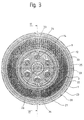
- the planet disks 22, 23 shown in FIG. 3 have a circular shape arranged coupling holes 33 (Fig.2), in which with Support rollers 24 provided clutch bolts 14 grip.
- This Coupling bolts 14 with the support rollers 24 penetrate the Coupling bores 33 of both planet discs 22 and 23.
- Die Coupling bolts 14 are from the rotating planet discs 22, 23 via the coupling bores 33 and the support rollers 24 taken along and form the mechanical output of the Reduction gear 15. You are direct in this function, or connected to the drive pulley 1 via the output hub 19.
- the Diameter of the coupling bores 33 in the planet disks 22, 23 are twice the eccentricity of the eccentric 28, 29 larger than that of the support rollers 24, so that Reduction gear 15 without clamping, but also without unnecessary play running.
- the reduced speed of the clutch pin 14, the clutch hub 19 and the traction sheave 1 results from the difference in the number of teeth between the planet discs 22, 23 and the internal teeth 21 in Gear housing 16, the number of teeth of Planetary disc toothing 34 is smaller than that of the Internal teeth 21 in the gear housing 16.
- Das Gear ratio is calculated from the number of teeth on the Internal toothing 21 divided by the difference in the number of teeth.
- the Planetary disks 22 and 23 rotate themselves when they rotate the motor shaft by the number of teeth difference in opposite Direction of rotation and of course also the coupling bolts 14 with the support rollers 24, the driven hub 19 and the traction sheave 1. With this type of gear, very large can be used in a small space Realize translation ratios.
- the double layer Execution of the gear 15 leads to the formation of two by 180 ° shifted points of attack of the downforce on the Internal teeth 21 in the gear housing 16 and thus one for the operation and the lifetime favorable load distribution.
- the reduction gear 15 is completely and the engine in essentially within the bell-shaped traction sheave 1.
- Fig.1 protrudes only a small part of the Three-phase winding 11 with the right-hand winding head somewhat beyond the silhouette of the traction sheave 1.
- Depending on Dimensioning of the stator winding can be done entirely within the Traction sheave silhuette lie.
- a three-phase motor a synchronous motor, the rotor is with permanent magnets equipped and the stator with pronounced poles and pole windings educated.
- the elevator drive results from the installation of a drum brake according to Fig. 4.
- a drum brake according to Fig. 4.
- the brake fitting itself consists of the brake drum 37 on both sides on the engine rear wall 4 attached brake lever bearings 35, each carry a brake lever 36 with a brake shoe 39.
- the two Brake levers 36 are actuated by an actuator 40 against spring force operated.
- A is preferably used as the drive for the actuator 40 Electromagnet used.
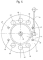
- FIG. 5 shows one with the Elevator drive combined disc brake.
- a brake disc 46 On the motor shaft 25 is attached a brake disc 46, which is on top of an actuator 40 is gripped in the form of a brake caliper.
- the schematic Representation of the actuator 40 is intended to leave the possibility open to operate them electromagnetically or oil-hydraulically.
- the braking torque is determined by a static one Spring force generated.
- the actuator is used Opening movement against this spring force.
- This type of brake too is equipped with the manual release lever 13.
- Fig.6 shows the, among other things for the holder of the Elevator drive, mentioned free annular surface 43 on the Engine housing rear wall 4.
- mounting holes 49 available, which, depending on the type of fastening technology, a thread can have.
- the number and arrangement of these mounting holes 49 is based on existing structural and other Conditions on the elevator system itself.
- mounting fittings come, depending on the installation location and type, not shown flat, angled or specially shaped metal profiles with integrated vibration damping for use.
- ventilation openings 48 for the Air circulation for engine and gearbox cooling in the example in the Form of large holes, available.
- the shape, number and Arrangement of the ventilation openings 48 depends on the required amount of cooling air, which in turn from the Motor power loss, transmission efficiency and Ambient temperature depends. It is also the possibility given an inevitable by fitting a blower Perform external ventilation.
- the motor housing rear wall 4 can also themselves can be executed directly as a mounting fitting, whereby then the engine housing rear wall 4 on at least one side Motor housing 3 protrudes, mounting holes in the protruding part identifies and, depending on the installation location and type of installation, accordingly molded end sections.
- the illustrated embodiment of the inventive Elevator drive is for a conveying load of 2000 kg and one Driving speed of up to 2.5 m / sec.
- the drive capacity can be correspondingly easier and are made smaller, for example with fewer rope grooves, smaller diameter or shorter overall length in the axial direction.
- the drive is preferably a normal one Three-phase short-circuit armature motor allows for power supply and control the use of conventional frequency and amplitude control electronics.
Landscapes
- Engineering & Computer Science (AREA)
- Civil Engineering (AREA)
- Mechanical Engineering (AREA)
- Structural Engineering (AREA)
- Cage And Drive Apparatuses For Elevators (AREA)
Priority Applications (1)
| Application Number | Priority Date | Filing Date | Title |
|---|---|---|---|
| EP97116480A EP0834463A1 (fr) | 1996-10-07 | 1997-09-22 | Dispositif compact d'entraínement pour ascenseur |
Applications Claiming Priority (3)
| Application Number | Priority Date | Filing Date | Title |
|---|---|---|---|
| EP96810669 | 1996-10-07 | ||
| EP96810669 | 1996-10-07 | ||
| EP97116480A EP0834463A1 (fr) | 1996-10-07 | 1997-09-22 | Dispositif compact d'entraínement pour ascenseur |
Publications (1)
| Publication Number | Publication Date |
|---|---|
| EP0834463A1 true EP0834463A1 (fr) | 1998-04-08 |
Family
ID=26144257
Family Applications (1)
| Application Number | Title | Priority Date | Filing Date |
|---|---|---|---|
| EP97116480A Withdrawn EP0834463A1 (fr) | 1996-10-07 | 1997-09-22 | Dispositif compact d'entraínement pour ascenseur |
Country Status (1)
| Country | Link |
|---|---|
| EP (1) | EP0834463A1 (fr) |
Cited By (16)
| Publication number | Priority date | Publication date | Assignee | Title |
|---|---|---|---|---|
| EP0901980A3 (fr) * | 1997-09-11 | 2000-11-15 | Alpha Getriebebau GmbH | Moteur d'ascenseur |
| EP1057772A3 (fr) * | 1999-06-02 | 2000-12-13 | Teijin Seiki Co., Ltd. | Ensemble d'entrainement pour ascenseur |
| EP1028081A3 (fr) * | 1999-02-10 | 2001-02-28 | Ziehl-Abegg GmbH & Co.KG | Entraínement d'élévateur avec moteur électrique |
| EP1074504A3 (fr) * | 1999-08-03 | 2002-02-13 | Teijin Seiki Co., Ltd. | Dispositif d'entraínement pour ascenseur |
| EP1074505A3 (fr) * | 1999-08-03 | 2002-02-13 | Teijin Seiki Co., Ltd. | Carénage pour dispositif d'entraínement d'ascenseur |
| DE10043013A1 (de) * | 2000-09-01 | 2002-04-04 | Ziehl Abegg Gmbh & Co Kg | Aufzugsantrieb mit Bremsvorrichtung |
| EP1319924A1 (fr) * | 2001-12-12 | 2003-06-18 | Brown & Sharpe Tesa S.A. | Appareil de mesure d'altitude |
| EP1411620A1 (fr) | 2002-10-18 | 2004-04-21 | Moteurs Leroy-Somer | Machine comportant une poulie et un moteur électrique, notamment pour ascenseur |
| WO2004035450A1 (fr) * | 2002-10-18 | 2004-04-29 | Mitsubishi Denki Kabushiki Kaisha | Machinerie d'ascenseur |
| KR100441043B1 (ko) * | 2002-08-28 | 2004-07-19 | 현대엘리베이터주식회사 | 엘리베이터용 박형 권상기 |
| KR100451317B1 (ko) * | 2002-09-17 | 2004-10-06 | 현대엘리베이터주식회사 | 엘리베이터용 박형 권상기 |
| KR100451316B1 (ko) * | 2002-09-11 | 2004-10-06 | 현대엘리베이터주식회사 | 엘리베이터용 박형 권상기 |
| EP1505030A1 (fr) * | 2003-08-08 | 2005-02-09 | Moteurs Leroy-Somer | Machine électrique, notamment pour ascenseur |
| CN102070080A (zh) * | 2010-06-13 | 2011-05-25 | 无锡核力重工有限公司 | 起重机运行机构的无齿轮传动系统 |
| CN102086007A (zh) * | 2010-06-13 | 2011-06-08 | 无锡核力重工有限公司 | 起重机起升机构的无齿轮传动系统 |
| CN110436297A (zh) * | 2018-05-03 | 2019-11-12 | 奥的斯电梯公司 | 制动盘释放装置、盘车装置、电梯救援套件和方法 |
Citations (5)
| Publication number | Priority date | Publication date | Assignee | Title |
|---|---|---|---|---|
| DE1148054B (de) * | 1959-07-02 | 1963-05-02 | Aloys Zeppenfeld Maschinenfabr | Hubwinde fuer Aufzuege |
| FR2505574A1 (fr) * | 1981-05-07 | 1982-11-12 | Elevator Gmbh | Moteur a cage d'ecureuil avec convertisseur commande de frequence |
| DE3840281A1 (de) * | 1988-11-30 | 1990-05-31 | Zahnradfabrik Friedrichshafen | Hebezeugantrieb |
| US5018603A (en) * | 1988-08-26 | 1991-05-28 | Mitsubishi Denki Kabushiki Kaisha | Elevator hoist apparatus |
| DE9416306U1 (de) * | 1994-10-10 | 1995-01-19 | Wittur Aufzugteile GmbH + Co., 85259 Wiedenzhausen | Antriebseinheit für ein Hebezeug |
-
1997
- 1997-09-22 EP EP97116480A patent/EP0834463A1/fr not_active Withdrawn
Patent Citations (5)
| Publication number | Priority date | Publication date | Assignee | Title |
|---|---|---|---|---|
| DE1148054B (de) * | 1959-07-02 | 1963-05-02 | Aloys Zeppenfeld Maschinenfabr | Hubwinde fuer Aufzuege |
| FR2505574A1 (fr) * | 1981-05-07 | 1982-11-12 | Elevator Gmbh | Moteur a cage d'ecureuil avec convertisseur commande de frequence |
| US5018603A (en) * | 1988-08-26 | 1991-05-28 | Mitsubishi Denki Kabushiki Kaisha | Elevator hoist apparatus |
| DE3840281A1 (de) * | 1988-11-30 | 1990-05-31 | Zahnradfabrik Friedrichshafen | Hebezeugantrieb |
| DE9416306U1 (de) * | 1994-10-10 | 1995-01-19 | Wittur Aufzugteile GmbH + Co., 85259 Wiedenzhausen | Antriebseinheit für ein Hebezeug |
Cited By (30)
| Publication number | Priority date | Publication date | Assignee | Title |
|---|---|---|---|---|
| EP0901980A3 (fr) * | 1997-09-11 | 2000-11-15 | Alpha Getriebebau GmbH | Moteur d'ascenseur |
| EP1028081A3 (fr) * | 1999-02-10 | 2001-02-28 | Ziehl-Abegg GmbH & Co.KG | Entraínement d'élévateur avec moteur électrique |
| US6766883B2 (en) | 1999-06-02 | 2004-07-27 | Teijin Seiki Co., Ltd. | Driving apparatus for elevator |
| EP1057772A3 (fr) * | 1999-06-02 | 2000-12-13 | Teijin Seiki Co., Ltd. | Ensemble d'entrainement pour ascenseur |
| US6578672B1 (en) | 1999-06-02 | 2003-06-17 | Teijin Seiki Co., Ltd. | Driving apparatus for elevator |
| EP1074504A3 (fr) * | 1999-08-03 | 2002-02-13 | Teijin Seiki Co., Ltd. | Dispositif d'entraínement pour ascenseur |
| EP1074505A3 (fr) * | 1999-08-03 | 2002-02-13 | Teijin Seiki Co., Ltd. | Carénage pour dispositif d'entraínement d'ascenseur |
| US6942066B1 (en) | 1999-08-03 | 2005-09-13 | Ts Corporation | Elevator apparatus |
| US6968925B1 (en) | 1999-08-03 | 2005-11-29 | Teijin Seiki Co., Ltd | Elevator apparatus |
| DE10043013A1 (de) * | 2000-09-01 | 2002-04-04 | Ziehl Abegg Gmbh & Co Kg | Aufzugsantrieb mit Bremsvorrichtung |
| DE10043013C2 (de) * | 2000-09-01 | 2002-07-18 | Ziehl Abegg Gmbh & Co Kg | Aufzugsantrieb mit Bremsvorrichtung |
| EP1319924A1 (fr) * | 2001-12-12 | 2003-06-18 | Brown & Sharpe Tesa S.A. | Appareil de mesure d'altitude |
| US6751884B2 (en) | 2001-12-12 | 2004-06-22 | Brown & Sharpe Tesa Sa | Column for measuring longitudinal dimensions |
| EP1319924B2 (fr) † | 2001-12-12 | 2012-04-11 | Tesa Sa | Appareil de mesure d'altitude |
| KR100441043B1 (ko) * | 2002-08-28 | 2004-07-19 | 현대엘리베이터주식회사 | 엘리베이터용 박형 권상기 |
| KR100451316B1 (ko) * | 2002-09-11 | 2004-10-06 | 현대엘리베이터주식회사 | 엘리베이터용 박형 권상기 |
| KR100451317B1 (ko) * | 2002-09-17 | 2004-10-06 | 현대엘리베이터주식회사 | 엘리베이터용 박형 권상기 |
| EP1411620A1 (fr) | 2002-10-18 | 2004-04-21 | Moteurs Leroy-Somer | Machine comportant une poulie et un moteur électrique, notamment pour ascenseur |
| WO2004035450A1 (fr) * | 2002-10-18 | 2004-04-29 | Mitsubishi Denki Kabushiki Kaisha | Machinerie d'ascenseur |
| US7195107B2 (en) | 2002-10-18 | 2007-03-27 | Moteurs Leroy-Somer | Machine having pulley coupled to rotor and partially overlying stator, elevator system including machine, and drive method |
| EP1411620B1 (fr) * | 2002-10-18 | 2012-08-08 | Moteurs Leroy-Somer | Machine comportant une poulie et un moteur électrique, notamment pour ascenseur |
| EP1505030A1 (fr) * | 2003-08-08 | 2005-02-09 | Moteurs Leroy-Somer | Machine électrique, notamment pour ascenseur |
| US7166946B2 (en) | 2003-08-08 | 2007-01-23 | Moteurs Leroy-Somer | Electrical machine, in particular for an elevator |
| FR2858723A1 (fr) * | 2003-08-08 | 2005-02-11 | Leroy Somer Moteurs | Machine electrique, notamment pour ascenseur |
| CN102086007A (zh) * | 2010-06-13 | 2011-06-08 | 无锡核力重工有限公司 | 起重机起升机构的无齿轮传动系统 |
| CN102070080A (zh) * | 2010-06-13 | 2011-05-25 | 无锡核力重工有限公司 | 起重机运行机构的无齿轮传动系统 |
| CN110436297A (zh) * | 2018-05-03 | 2019-11-12 | 奥的斯电梯公司 | 制动盘释放装置、盘车装置、电梯救援套件和方法 |
| EP3626669A1 (fr) * | 2018-05-03 | 2020-03-25 | Otis Elevator Company | Dispositif de libération de disque de frein, dispositif de rotation, kit de sauvetage d'ascenseur et procédé |
| US11667495B2 (en) | 2018-05-03 | 2023-06-06 | Otis Elevator Company | Brake disc releasing device, turning device, elevator rescue kit and method |
| US12214994B2 (en) | 2018-05-03 | 2025-02-04 | Otis Elevator Company | Brake disc releasing device, turning device, elevator rescue kit and method |
Similar Documents
| Publication | Publication Date | Title |
|---|---|---|
| EP0834463A1 (fr) | Dispositif compact d'entraínement pour ascenseur | |
| DE69420329T2 (de) | Im Gegengewicht eingebauter Aufzugsmotor | |
| DE69403684T2 (de) | Aufzugsmotor im Gegengewicht eingesetzt | |
| DE69835806T2 (de) | Verfahren in einem aufzugsantrieb | |
| DE69621369T2 (de) | Aufzugsantriebsmaschine | |
| DE69909133T2 (de) | Aufzugsantrieb mit gegenläufigen rotoren | |
| EP3317222B1 (fr) | Système de treuil de levage | |
| DE69423519T2 (de) | Aufzugsmaschinerie | |
| EP0706968B1 (fr) | Unité d'entraínement pour un appareil de levage | |
| DE3739537A1 (de) | Elektromagnetisch betaetigbare reibscheibenkupplung | |
| DE3216978A1 (de) | Kaefiglaeufermotor fuer ein hebezeug, insbesondere fuer einen aufzug | |
| DE69716584T2 (de) | Vorrichtung und antrieb zum transport von personen | |
| EP0949743A2 (fr) | Machine électrique, notamment pour dispositif d'entraínement pour ascenseur | |
| DE60204256T2 (de) | Durch Drehmoment lösbare Scheibenbremse | |
| DE69630066T2 (de) | Notantriebseinheit für eine Aufzugsmaschine | |
| DE19832208C1 (de) | Getriebelose Aufzugsmaschine mit einem Synchron-Außenläufermotor | |
| EP1069068B1 (fr) | Entraînement compact pour un ascenseur | |
| EP0878430A2 (fr) | Dispositif de levage, en particuler ascenseur, avec un moteur électrique et utilisation du moteur électrique | |
| EP0729912B1 (fr) | Palan à chaíne muni d'un accouplement actionné par un frein | |
| EP4265556B1 (fr) | Machine d'entraînement pour ascenseur | |
| EP0901980B1 (fr) | Moteur d'ascenseur | |
| DE102009029877A1 (de) | Torquemotor mit Brems- und/oder Halteeinrichtung | |
| DE19905390C1 (de) | Aufzugsantrieb mit elektrischem Antriebsmotor | |
| DE10005075A1 (de) | Elektrisch angetriebene Winde, insbesondere Theaterwinde | |
| EP1627841B1 (fr) | Entraînement pour un ascenseur |
Legal Events
| Date | Code | Title | Description |
|---|---|---|---|
| PUAI | Public reference made under article 153(3) epc to a published international application that has entered the european phase |
Free format text: ORIGINAL CODE: 0009012 |
|
| AK | Designated contracting states |
Kind code of ref document: A1 Designated state(s): AT CH DE ES FR GB IT LI |
|
| 17P | Request for examination filed |
Effective date: 19980917 |
|
| AKX | Designation fees paid |
Free format text: AT CH DE ES FR GB IT LI |
|
| RBV | Designated contracting states (corrected) |
Designated state(s): AT CH DE ES FR GB IT LI |
|
| 17Q | First examination report despatched |
Effective date: 20010427 |
|
| STAA | Information on the status of an ep patent application or granted ep patent |
Free format text: STATUS: THE APPLICATION IS DEEMED TO BE WITHDRAWN |
|
| 18D | Application deemed to be withdrawn |
Effective date: 20011108 |