EP0834653A2 - Pompe péristaltique - Google Patents
Pompe péristaltique Download PDFInfo
- Publication number
- EP0834653A2 EP0834653A2 EP97307354A EP97307354A EP0834653A2 EP 0834653 A2 EP0834653 A2 EP 0834653A2 EP 97307354 A EP97307354 A EP 97307354A EP 97307354 A EP97307354 A EP 97307354A EP 0834653 A2 EP0834653 A2 EP 0834653A2
- Authority
- EP
- European Patent Office
- Prior art keywords
- rotor
- hub
- actuating part
- tube
- actuating
- Prior art date
- Legal status (The legal status is an assumption and is not a legal conclusion. Google has not performed a legal analysis and makes no representation as to the accuracy of the status listed.)
- Withdrawn
Links
Images

Classifications
-
- F—MECHANICAL ENGINEERING; LIGHTING; HEATING; WEAPONS; BLASTING
- F04—POSITIVE - DISPLACEMENT MACHINES FOR LIQUIDS; PUMPS FOR LIQUIDS OR ELASTIC FLUIDS
- F04B—POSITIVE-DISPLACEMENT MACHINES FOR LIQUIDS; PUMPS
- F04B43/00—Machines, pumps, or pumping installations having flexible working members
- F04B43/12—Machines, pumps, or pumping installations having flexible working members having peristaltic action
- F04B43/1253—Machines, pumps, or pumping installations having flexible working members having peristaltic action by using two or more rollers as squeezing elements, the rollers moving on an arc of a circle during squeezing
- F04B43/1276—Means for pushing the rollers against the tubular flexible member
Definitions
- the present invention relates to a peristaltic pump, and more particularly to a rotor for a peristaltic pump.
- a peristaltic pump includes a rotor assembly which has tube-engaging surfaces for occluding a flexible tube within the pump. As the tube-engaging surfaces rotate, fluid in the tube is forced along the tube. Thus pumping of the fluid is achieved. It is desirable to adjust the amount by which the tube is occluded by the engaging surfaces.
- Previous designs of rotor assembly include lubricated shims located between the rotor hub and the tube-engaging surfaces. Adjustment of the amount of occlusion of the tube is achieved by adding or removing shims. Such an operation is time-consuming, potentially inaccurate and can cause undesirable contamination of other parts of the pump.
- a rotor for a peristaltic pump comprising:
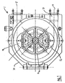
- the peristaltic pump 1 shown in Figure 1 comprises a housing 10 within which a rotor 11 is rotatable about an axis R.
- a flexible tube 7 is arranged in a U-shape around the rotor 11.
- Shoes or lobes 12 which bear on the tube 7 are carried by the rotor 11 on opposite sides of the axis R.
- the rotor 11 is driven about the axis R, for example by means of an electric motor.
- the lobes 12 are thereby rotated and constrict the tube so as to occlude the passageway running through the tube.
- the occlusion caused by each lobe 12 translates along the length of the tube 7. In this way, fluid carried in the tube 7 is forced from one port 8 or 9 of the pump to the other port 9 or 8 of the pump, depending on the direction of rotation of the rotor 11.
- the spacing of the lobes 12 from the axis R determines the amount by which the tube 7 is occluded when the pump is in use.
- the amount of occlusion affects the flow rate of the pump and the amount of wear experienced by the tube.
- the spacing of the lobes 12 from the axis R is adjusted by the use of shims 13 placed between each lobe 12 and the rotor 11.
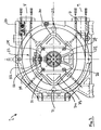
- the pump shown in Figure 2 comprises a housing 20 and a substantially U-shaped flexible tube 7, as in the previously-considered design, but has a different rotor assembly, as shown in more detail in Figures 3 and 4.
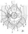
- the rotor assembly comprises a main rotor body 21 having a hub 211 provided with a radial extension 212 which carries two arms 213.
- Each of the arms 213 is shaped so as to serve as a lobe having a tube-engaging region 214 similar in profile to those described with reference to Figure 1.
- Each arm 22 is connected at one end to the radial extension 212 of the main rotor body 21.
- the arms 213 extend from that extension 26 to opposite sides of the axis of rotation R as shown in Figures 2 to 4.
- Each arm terminates at a free end 215 which is situated substantially opposite the radial extension 212.
- Adjustment means 22 is provided which comprises an adjustment element in the form of a wedge 221, and a screwthreaded element in the form of an adjusting bolt 222.
- the wedge 221 is located between the free ends 215 of the arms 213.
- the adjusting bolt 222 passes through the wedge 221 and is threaded into a portion 216 of the hub 211.
- the adjustment means 22 is used to adjust the spacing of the tube-engaging regions 214 of the arms 213 from the axis of rotation R.
- the adjuster bolt 222 is screwed into the part 216. This causes the wedge 221 to move towards the axis of rotation R.
- Cam faces 223 of the wedge 221 engage corresponding faces 218 at the free ends of the arms 213 so that as the wedge moves inwardly, the free ends 215 of the arms 213 are moved apart from each other as indicated by arrows C in Figure 3.
- the arms hinge elastically about a portion 217 of the rotor 21. The resilience of the material of the rotor 21 biasses the arms into contact with the wedge 221.
- the adjusting bolt 222 is screwed out of the portion 216, thereby allowing the wedge 221 to move outwardly from the axis R.
- the resilient nature of the hinges formed at portions 217 causes the arms 213 to move inwardly, thereby forcing the wedge 221 outwardly into contact with the head of the adjusting bolt 222.
- the free end regions 215 of the arms 213 carry measuring marks 230 and a scale 231 is marked on the wedge, so that the amount of displacement of the tube-engaging regions can be determined accurately and simply.
- the scale 231 is preferably graduated in terms of millimetres of occlusion of the tube.
- the rotor is shown in use in Figure 4, in which the arms 213 are in an adjusted position in which the tube 7 is completely occluded in the region 71.
- the rotor (body) rotates about axis R, the occluded region 71 moves along the tube 7 so that liquid contained within the tube is pumped from one end of the tube to the other.
- the rotor body 21, comprising the hub 211, the radial extension 212, the arms 213, with the regions 214 and the portion 216, is preferably made from spheroidal graphite cast iron which has elastic properties required to form the elastic hinges 217. Casting the assembly from such a material enables a single casting to be made.
- the wedge is preferably machined from aluminium.
- the rotor 21 shown in Figures 2 to 4 has a reduced number of components compared with that shown in Figure 1, and aids simplified and foolproof adjustment of the occlusion of the tube. Adjustment is made by one simple action which adjusts the position of both of the lobes.
- the design also provides clear indication of the occlusion setting, and can achieve prolonged life of the tube by enabling the occlusion setting to be optimised.
Landscapes
- Engineering & Computer Science (AREA)
- Mechanical Engineering (AREA)
- General Engineering & Computer Science (AREA)
- Reciprocating Pumps (AREA)
Applications Claiming Priority (2)
| Application Number | Priority Date | Filing Date | Title |
|---|---|---|---|
| GB9620850 | 1996-10-07 | ||
| GB9620850A GB2317924B (en) | 1996-10-07 | 1996-10-07 | Peristaltic pump |
Publications (2)
| Publication Number | Publication Date |
|---|---|
| EP0834653A2 true EP0834653A2 (fr) | 1998-04-08 |
| EP0834653A3 EP0834653A3 (fr) | 2000-06-14 |
Family
ID=10801042
Family Applications (1)
| Application Number | Title | Priority Date | Filing Date |
|---|---|---|---|
| EP97307354A Withdrawn EP0834653A3 (fr) | 1996-10-07 | 1997-09-22 | Pompe péristaltique |
Country Status (3)
| Country | Link |
|---|---|
| US (1) | US6019582A (fr) |
| EP (1) | EP0834653A3 (fr) |
| GB (1) | GB2317924B (fr) |
Cited By (6)
| Publication number | Priority date | Publication date | Assignee | Title |
|---|---|---|---|---|
| GB2416810A (en) * | 2004-08-06 | 2006-02-08 | Verder Ltd | Peristaltic pump and rotor |
| US7478999B2 (en) | 2004-03-04 | 2009-01-20 | Cole-Parmer Instrument Company | Peristaltic pump |
| USD605286S1 (en) | 2007-01-19 | 2009-12-01 | Cole-Parmer Instrument Company | Tube retainer |
| US7980835B2 (en) | 2007-01-19 | 2011-07-19 | Cole-Parmer Instrument Company | Tube retainer system for a peristaltic pump |
| US8052399B2 (en) | 2007-10-18 | 2011-11-08 | Cole-Parmer Instrument Company | Peristaltic pump |
| CN105673463A (zh) * | 2016-04-01 | 2016-06-15 | 陈潜 | 一种具有散热装置的软管泵 |
Families Citing this family (12)
| Publication number | Priority date | Publication date | Assignee | Title |
|---|---|---|---|---|
| JP2001176027A (ja) * | 1999-12-14 | 2001-06-29 | Nec Corp | 磁気抵抗効果ヘッド及びこれを用いた磁気記憶装置 |
| ITGE20020033A1 (it) † | 2002-04-24 | 2003-10-24 | Schiavi Spa | Metodo di lavaggio automatico del circuito di inchiostrazione nelle macchine da stampa rotative, ed impianto per l'attuazione di detto metod |
| US8550310B2 (en) * | 2007-12-05 | 2013-10-08 | Bunn-O-Matic Corporation | Peristaltic pump |
| US8197236B2 (en) * | 2008-04-25 | 2012-06-12 | Medtronic, Inc. | Adjustable roller pump rotor |
| US9072540B2 (en) | 2009-08-12 | 2015-07-07 | Boston Scientific Limited | Adaptive tubing cassettes for use in connection with interventional catheter assemblies |
| US8388582B2 (en) | 2009-08-12 | 2013-03-05 | Medrad, Inc. | Systems and methods for operating interventional catheters using a common operating console and adaptive interface components |
| US9239049B2 (en) | 2010-07-16 | 2016-01-19 | Boston Scientific Limited | Peristaltic pump having a self-closing occlusion bed |
| DE102011015110B3 (de) | 2011-03-19 | 2012-01-26 | Ebm-Papst St. Georgen Gmbh & Co. Kg | Dosiersystem |
| US9710610B2 (en) | 2012-07-25 | 2017-07-18 | Covidien Lp | Enteral feeding pump with flow adjustment |
| CA2791344C (fr) | 2012-09-26 | 2019-07-16 | Capmatic Ltee | Pompe peristaltique |
| CN105579080B (zh) | 2013-09-24 | 2019-09-10 | Kpr美国有限责任公司 | 喂送套件和肠内喂送泵 |
| EP3483440B1 (fr) | 2017-11-08 | 2020-05-27 | Oina VV AB | Pompe péristaltique |
Family Cites Families (15)
| Publication number | Priority date | Publication date | Assignee | Title |
|---|---|---|---|---|
| GB193574A (en) * | 1921-12-16 | 1923-03-01 | Clifford Charles Champeney | An improved appliance for raising liquids |
| NL15239C (fr) * | 1924-12-24 | 1900-01-01 | ||
| GB628785A (en) * | 1947-10-16 | 1949-09-05 | Denis Withinshaw Rowley | Improvements in flexible tube pumps |
| US3079686A (en) * | 1961-12-22 | 1963-03-05 | Earl B Christy | Handle construction for sliding blade knives |
| US3644068A (en) * | 1970-03-12 | 1972-02-22 | Kenneth Leeds | Pump arrangement |
| US3787148A (en) * | 1972-09-26 | 1974-01-22 | Kopf D Syst | Roller pump |
| IT7428990U1 (it) * | 1974-12-17 | 1976-06-17 | Dasco Spa | Pompa con coppia di rulli registrabili per la circolazione extracorporea del sangue in un impianto di rene artificiale |
| IT1039598B (it) * | 1975-07-01 | 1979-12-10 | Bioengineering Research | Testata per pompa a rulli a funzionamento alternativo particcolarmente per la circolazione extra corporea del sangue |
| US4174193A (en) * | 1976-12-16 | 1979-11-13 | Senko Medical Instrument Mfg. Co., Ltd. | Peristatic pump with hose positioning means and pressure adjustment apparatus |
| US4184815A (en) * | 1977-03-14 | 1980-01-22 | Extracorporeal Medical Specialties, Inc. | Roller pump rotor with integral spring arms |
| US4214855A (en) * | 1977-12-21 | 1980-07-29 | Gerritsen Jan W | Peristaltic type pump |
| FR2519381B1 (fr) * | 1981-12-31 | 1986-09-26 | Delasco Sa | Pompe peristaltique |
| US4548553A (en) * | 1984-09-24 | 1985-10-22 | Ferster Reuben I | Peristaltic pump structure |
| DE4214916A1 (de) * | 1992-05-11 | 1993-11-18 | Allweiler Ag | Schlauchpumpe |
| WO1994005345A1 (fr) * | 1992-09-02 | 1994-03-17 | Valery Viktorovich Skobelev | Pompe pour liquides biologiques |
-
1996
- 1996-10-07 GB GB9620850A patent/GB2317924B/en not_active Expired - Lifetime
-
1997
- 1997-09-22 EP EP97307354A patent/EP0834653A3/fr not_active Withdrawn
- 1997-10-06 US US08/944,302 patent/US6019582A/en not_active Expired - Lifetime
Non-Patent Citations (1)
| Title |
|---|
| None |
Cited By (8)
| Publication number | Priority date | Publication date | Assignee | Title |
|---|---|---|---|---|
| US7478999B2 (en) | 2004-03-04 | 2009-01-20 | Cole-Parmer Instrument Company | Peristaltic pump |
| GB2416810A (en) * | 2004-08-06 | 2006-02-08 | Verder Ltd | Peristaltic pump and rotor |
| GB2416810B (en) * | 2004-08-06 | 2009-12-09 | Verder Ltd | Peristaltic pump and rotor |
| USD605286S1 (en) | 2007-01-19 | 2009-12-01 | Cole-Parmer Instrument Company | Tube retainer |
| US7980835B2 (en) | 2007-01-19 | 2011-07-19 | Cole-Parmer Instrument Company | Tube retainer system for a peristaltic pump |
| US8052399B2 (en) | 2007-10-18 | 2011-11-08 | Cole-Parmer Instrument Company | Peristaltic pump |
| CN105673463A (zh) * | 2016-04-01 | 2016-06-15 | 陈潜 | 一种具有散热装置的软管泵 |
| CN105673463B (zh) * | 2016-04-01 | 2018-05-22 | 陈潜 | 一种具有散热装置的软管泵 |
Also Published As
| Publication number | Publication date |
|---|---|
| US6019582A (en) | 2000-02-01 |
| GB9620850D0 (en) | 1996-11-27 |
| EP0834653A3 (fr) | 2000-06-14 |
| GB2317924A (en) | 1998-04-08 |
| GB2317924B (en) | 2000-07-12 |
Similar Documents
| Publication | Publication Date | Title |
|---|---|---|
| US6019582A (en) | Peristaltic pump having an elastic adjustable rotor body | |
| US4519754A (en) | Peristaltic pump having variable occlusion rates | |
| US10151309B2 (en) | Peristaltic pump | |
| CA2020926A1 (fr) | Pompe peristaltique dotee d'un mecanisme de maintien de l'ecoulement lineaire | |
| JPH01200068A (ja) | アキシャルピストンポンプ | |
| JPS62501021A (ja) | 斜板位置決め固定装置 | |
| KR930013479A (ko) | 경사판형 압축기 | |
| JPS6228201A (ja) | プランジヤオイルポンプを有するチエ−ンソ− | |
| US4780069A (en) | Directlly actuated vane-type pump | |
| US6547531B1 (en) | Variable-displacement axial piston pump | |
| KR940007757B1 (ko) | 연동 펌프용 압력면 | |
| CN100465448C (zh) | 单叶片真空泵 | |
| CA2314415A1 (fr) | Pompe volumetrique et palier de butee | |
| EP0111619A1 (fr) | Pompe à engrenage sphérique | |
| JP3297816B2 (ja) | 作動油圧力エネルギー変換装置 | |
| WO1995012054A1 (fr) | Machine a plateau oscillant | |
| EP0116832A1 (fr) | Procédé et dispositif pour réduire le bruit d'exploitation dans les pompes et les moteur à pistons axiaux | |
| US6367368B1 (en) | Variable displacement compressor having piston anti-rotation structure | |
| US5161962A (en) | Fluid pump comprised by blades | |
| KR19990007811A (ko) | 개량된 사판 지지 수단을 가진 용량 가변형 사판식 압축기 | |
| RU2100646C1 (ru) | Аксиально-поршневой насос с регулируемым рабочим объемом | |
| JPH0771378A (ja) | 回転ピストンポンプ | |
| KR20010062604A (ko) | 피봇 핀을 갖는 가변 변위 회전 경사판형 압축기 | |
| EP0495602B1 (fr) | Compresseur de fluides à courant axial | |
| US4929217A (en) | Variable speed pulley |
Legal Events
| Date | Code | Title | Description |
|---|---|---|---|
| PUAI | Public reference made under article 153(3) epc to a published international application that has entered the european phase |
Free format text: ORIGINAL CODE: 0009012 |
|
| AK | Designated contracting states |
Kind code of ref document: A2 Designated state(s): DE FR GB IT NL |
|
| AX | Request for extension of the european patent |
Free format text: AL;LT;LV;RO;SI |
|
| PUAL | Search report despatched |
Free format text: ORIGINAL CODE: 0009013 |
|
| AK | Designated contracting states |
Kind code of ref document: A3 Designated state(s): AT BE CH DE DK ES FI FR GB GR IE IT LI LU MC NL PT SE |
|
| AX | Request for extension of the european patent |
Free format text: AL;LT;LV;RO;SI |
|
| 17P | Request for examination filed |
Effective date: 20001204 |
|
| AKX | Designation fees paid |
Free format text: DE FR GB IT NL |
|
| GRAP | Despatch of communication of intention to grant a patent |
Free format text: ORIGINAL CODE: EPIDOSNIGR1 |
|
| STAA | Information on the status of an ep patent application or granted ep patent |
Free format text: STATUS: THE APPLICATION IS DEEMED TO BE WITHDRAWN |
|
| 18D | Application deemed to be withdrawn |
Effective date: 20040803 |