EP0834701A1 - Backofen mit innenbelüfteter Türdichtung - Google Patents
Backofen mit innenbelüfteter Türdichtung Download PDFInfo
- Publication number
- EP0834701A1 EP0834701A1 EP97115980A EP97115980A EP0834701A1 EP 0834701 A1 EP0834701 A1 EP 0834701A1 EP 97115980 A EP97115980 A EP 97115980A EP 97115980 A EP97115980 A EP 97115980A EP 0834701 A1 EP0834701 A1 EP 0834701A1
- Authority
- EP
- European Patent Office
- Prior art keywords
- door seal
- air
- oven
- door
- seal
- Prior art date
- Legal status (The legal status is an assumption and is not a legal conclusion. Google has not performed a legal analysis and makes no representation as to the accuracy of the status listed.)
- Granted
Links
- 238000009423 ventilation Methods 0.000 claims abstract description 9
- 238000001816 cooling Methods 0.000 claims description 46
- 238000007789 sealing Methods 0.000 claims description 31
- 229920002379 silicone rubber Polymers 0.000 claims description 3
- 239000004945 silicone rubber Substances 0.000 claims description 3
- 239000003570 air Substances 0.000 description 116
- 229920001296 polysiloxane Polymers 0.000 description 7
- 238000000197 pyrolysis Methods 0.000 description 5
- 230000000694 effects Effects 0.000 description 4
- 239000000463 material Substances 0.000 description 4
- 239000012080 ambient air Substances 0.000 description 3
- 230000008901 benefit Effects 0.000 description 3
- 238000004140 cleaning Methods 0.000 description 3
- 238000004519 manufacturing process Methods 0.000 description 2
- 239000002184 metal Substances 0.000 description 2
- 230000009286 beneficial effect Effects 0.000 description 1
- 230000001419 dependent effect Effects 0.000 description 1
- 230000003670 easy-to-clean Effects 0.000 description 1
- 238000005516 engineering process Methods 0.000 description 1
- 239000011521 glass Substances 0.000 description 1
- 239000004519 grease Substances 0.000 description 1
- 238000009434 installation Methods 0.000 description 1
- 230000003993 interaction Effects 0.000 description 1
- 230000005012 migration Effects 0.000 description 1
- 238000013508 migration Methods 0.000 description 1
- 230000008439 repair process Effects 0.000 description 1
- 239000003566 sealing material Substances 0.000 description 1
- 238000000926 separation method Methods 0.000 description 1
- 230000007704 transition Effects 0.000 description 1
- 230000003313 weakening effect Effects 0.000 description 1
Images

Classifications
-
- F—MECHANICAL ENGINEERING; LIGHTING; HEATING; WEAPONS; BLASTING
- F24—HEATING; RANGES; VENTILATING
- F24C—DOMESTIC STOVES OR RANGES ; DETAILS OF DOMESTIC STOVES OR RANGES, OF GENERAL APPLICATION
- F24C15/00—Details
- F24C15/006—Arrangements for circulation of cooling air
-
- F—MECHANICAL ENGINEERING; LIGHTING; HEATING; WEAPONS; BLASTING
- F24—HEATING; RANGES; VENTILATING
- F24C—DOMESTIC STOVES OR RANGES ; DETAILS OF DOMESTIC STOVES OR RANGES, OF GENERAL APPLICATION
- F24C15/00—Details
- F24C15/02—Doors specially adapted for stoves or ranges
- F24C15/021—Doors specially adapted for stoves or ranges sealings for doors or transparent panel
Definitions
- the invention relates to an oven with an oven muffle, one oven door and one between the oven door and the front of the oven muffle arranged door seal.
- Door seals for ovens that lock the oven door against the Sealing the front of the oven muffle are in many Embodiments known. You are at the front of the Oven muffle or attached to the oven door and either as angled, laterally open silicone hoses or designed as metal mesh strands.
- silicone seals also for pyrolysis devices were used, this was with a significant design effort connected to the front of the device to be designed so that sufficient in the area of the seal low temperatures prevail, i.e. that of silicone seals maximum tolerable limit temperatures of Do not exceed 250 to 270 ° C.
- pyrolysis devices are currently mostly used metal mesh seals filled with glass mesh are used, that during pyrolytic self-cleaning withstand the very high operating temperatures. Due to the high thermal expansion of this type of seal however, when attaching the seal Special arrangements are made to ensure satisfactory To ensure sealing. Also are these seals are heavy in their porous surface structure cleaned and hardened grease with time, which reduces the sealing effect. About that assembly is also difficult.
- the invention lies in consideration of the above State of the art based on the technical problem, an oven with improved door seal, in particular for pyrolysis devices or other ovens with very high To create operating temperatures.
- This problem is in an oven of the type described Art solved in that he has a door seal ventilation system for cooling the door seal with in your Air flowing inside.
- the door seal as a hollow profile with a continuous interior formed and has an air inlet opening and Air outlet opening.
- a door seal air duct with a blower is provided in the area of the air inlet opening the door seal has a higher air pressure than in the area of the air outlet opening of the door seal generate so that cooling air due to the air pressure difference positively guided through the interior of the door seal flows.
- Components of the invention are thus a hollow profile trained door seal and a coordinated Air routing, which is generally called a door seal ventilation system can designate.
- a door seal ventilation system By the inside of the hollow profile flowing air can act on the door seal Temperatures even at higher operating temperatures of the oven are kept so low that the maximum compatible with the respective sealing material Temperatures are not exceeded. This makes one weakening of material due to high temperatures counteracted and thus the life of the door seal elevated. It is also possible to use materials with a lot good sealing properties, but relatively low maximum tolerable temperatures as standard in ovens to use.
- the door seal designed as a hollow profile is preferably closed on the side.
- the door seal For the function of the door seal, it is sufficient if it has one only air inlet opening to enter through the Door seal air duct generated and to the air inlet opening guided cooling air and a single air outlet to exit through the door seal has flowed cooling air.
- the door seal also has several air inlet openings and / or include air outlet openings can. For the sake of clarity, the following is however predominantly from “the air inlet opening” and “the air outlet opening” spoken.
- the door seal can in principle be made in one piece be.
- the air inlet opening and the air outlet opening are located here essentially side by side.
- a one piece Training the door seal leads to the fact that there is a strong temperature gradient in the direction of flow of the cooling air trains. Therefore the door seal is preferred divided into two sealing strands, each Sealing strip as a hollow profile with a continuous Interior is formed and at least one each Air inlet opening and at least one air outlet opening having.
- the corresponding ones are in each case Air inlet openings and the corresponding ones Air outlet openings of the sealing strands in areas with the same air pressure.
- both strands are essentially the same length are, i.e. one half of the circumference of the oven door seal against the front of the oven muffle. It can be a common at the corresponding ends Air inlet opening and / or a common one Air outlet opening should be available.
- An advantageous design of the door seal can provide that they are at their air inlet opening and / or their Air outlet opening for connecting the door seal the door seal air duct has a sealing edge.
- This sealing edge works with one on the seal side Provided end of the door seal air duct, opposite the air inlet and / or air outlet opening Sealing surface together. This makes a closed one Connection space formed and a forced routing of the cooling air and therefore sufficient to cool the door seal large air transition between the door seal air duct and the air inlet opening and / or the air outlet opening causes.
- a well sealing connection of the air inlet and / or Air outlet openings of the door seal to the door seal air duct is particularly advantageous if the Door seal, as is preferably suggested, on the Oven door is attached and thus a larger constructive and spatial separation of seal and air supply exists as with one on the front of the oven muffle attached door seal. An attachment of the Ventilated door seal on the front of the oven muffle is also possible.
- the air can exit the cooling air from the door seal Air outlet opening as a hole or for example slot-shaped material recess without a specially shaped one Sealing edge be realized. The same can apply to the realization of the air inlet opening.
- the inside diameter of the hollow profile is approx. 6 to 8 mm.
- the outer diameter measures approximately 10 to 12 mm.
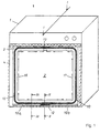
- Fig. 1 shows an oven 1 according to the invention with a Oven muffle 2, an oven door shown in dashed lines 4 and one between the oven door 4 and the Front 3 of the oven muffle 2 arranged door seal 10.
- the hollow profile 11 with a continuous interior trained door seal 10 two sealing strands 10a and 10b, which are essentially the same length and each one half of the circumference of the oven door 4 against the Seal the front 3 of the oven muffle 2.
- the two Sealing strands 10a and 10b each have at their ends a common air inlet opening 12 and a common one Air outlet opening 13, which, based on the lower or upper horizontal section of the door seal 10, are each arranged essentially in the middle.
- the arrows 16 and 17 mark the respective predetermined by the sealing strip 10a or 10b Partial flow path of the cooling air inside the door seal 10th
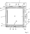
- the door seal ventilation system 30 which consists of the internally ventilated door seal 10 and one Door seal air duct 20 exists.
- the door seal air duct 20 includes the elements used to cool the The door seal generates and guides the required cooling air the door seal. To do this, it points outside the Oven muffle 2 arranged fan 21, for example a radial fan or a cross flow fan can be and in the case shown between one Oven muffle wall 7 and a rear oven outer plate 6c lies.
- a first flow path section 24 of the door seal air duct 20 for the cooling air from the blower 21 to the door seal 10 is determined by an outflow channel 29a which through the oven muffle wall 7, a lower oven outer plate 6a, the rear oven outer plate 6c and lateral outer sheets is formed.
- the flow path from the blower 21 to the door seal 10 is considered as a whole Pressure side 22 of the door seal air duct 20 designated. There is a pressure side 22 in comparison to the surroundings of the oven 1 increased air pressure.
- the air inlet opening 12 of the door seal 10 is on the pressure side 22 of the door seal air duct 20 is arranged.
- 23 under suction side the path from the door seal 10 to the suction side connection to understand the blower 21.
- the oven muffle wall 7, an upper oven outer plate 6b, the rear Oven outer plate 6c and side outer plates form an inflow channel 29b, which has a second flow path section 28 of the door seal air duct 20 for the cooling air to the blower 21 determined.
- the air outlet 13 of the door seal 10 is on the suction side 23 of the door seal air duct 20 is arranged.
- the cooling of the door seal 10 is effected in that Cooling air due to a between the air inlet opening 12 and the air outlet opening 13 existing air pressure difference flows through the hollow profile 11. It is advantageous if the door seal air duct 20 as shown a defined print page 22 and a defined one Has suction side 23. Due to the arrangement of the air outlet opening 13 on the suction side 23 is the differential pressure and thus increases the flow and the cooling effect.
- a door seal air duct can also be used be, whose blowers the cooling air in the area of the rear oven outer plate 6c immediately sucks the environment, then the air outlet 13 is opened directly into the ambient air, so that the differential pressure only from the overpressure on the pressure side 22 of the air duct 20 results.
- the continuous cooling of the door seal 10 has the significant advantage that even with pyrolysis or other ovens with very high operating temperatures for example based on silicone rubber, can be used without this cooling cannot withstand the high operating temperatures would.
- the cooling air flows in the vertical sections of the door seal 10 from the bottom up
- the thermal flow behavior supports air transportation. Exploiting the thermal flow behavior of air has the advantage that the blower 21 can be made smaller. Also an embodiment in which the inlet opening 12 in the upper horizontal section of the door seal 10 and the outlet opening 13 in the lower horizontal section the door seal 10 is located, however, under May be beneficial.
- the door seal cooling air is thus a subset of the Cooling air of the jacket cooling. This will be part of the heated jacket cooling air on the pressure side 22 of the Blower 21 before leaving the oven 1 on the Door seal air duct 20 of the air inlet opening 12 fed.
- the equipment of the oven 1 with only one of both Door seal and blower cooling fans 21 reduces the space to be accommodated outside the oven muffle 2 technical equipment, lowers manufacturing costs and reduces the need for repairs Oven 1.
- the door seal ventilation system 30 is the pressure side 22 advantageously at the lower horizontal section and the suction side 23 at the upper horizontal section of the Door seal 10 connected. This arrangement will the part of the door seal not used for cooling Jacket cooling air in the lower front area of the oven 1 released into the ambient air. This will Operator looking through the oven door into the oven muffle 2 not from the jacket cooling air flow Blown face.
- FIG. 3 and 4 are cross sections through the lower horizontal section the door seal 10 along the lines II-II and III-III from Fig. 1. They illustrate the interaction the door seal 10 and the door seal air duct 20 within the door seal ventilation system 30.
- Fig. 3 shows the connection of the door seal 10 to the door seal air duct 20
- Fig. 4 shows the arrangement outside represents the connection area.
- both figures is designed as a hollow profile 11, with one of the Attachment serving profile extension 14 equipped
- Door seal 10 can be seen by means of an oven door side provided, cross-section hook-shaped mounting rail 8 is attached to the oven door 4.
- the oven door 4 has a suitable groove for receiving the door seal so that it does not protrude so far.
- the storage in a groove has a warping effect and thermal expansion-related migration of the door seal opposite.
- Fig. 3 is the air inlet opening 12 of the door seal 10 seen in cross section. It can be clearly seen that the hollow profile 11 of the door seal 10 on one side Air inlet opening 12 is open.
- the air inlet opening 12 has a thickened sealing edge 15 on the ring-shaped in the spatial training is, for example, lip-shaped or bead-like can be.
- the sealing edge 15 acts with an air duct side provided sealing surface 25 under training a closed connection space 18 together in such a way that he closes the oven door 4 against the from the front 3 of the oven muffle 2 and the lower one Oven outer plate 6a formed sealing surface 25 pressed and forms a flat connection contact with it.
- the cooling air enters the terminal space 18 and thus in the air inlet opening 12 of the door seal 10.
- FIG 4 shows one outside the air inlet opening 12 lying cross section through the lower horizontal section the door seal 10. It can be seen that the Door seal 10 formed here without an exit gap Sealing surface 25 is present.
- the figure shows optional here existing, for example, slit-shaped Outlet openings 26 on the front of the lower outer plate 6a, through which part of the cooling air which the Jacket cooling of the oven muffle 2 is used in the ambient air exit.
- the cooling air throughput depends on the door seal 10 of numerous influencing factors, in particular of the strength of the blower 21, the cross section of the outflow channel 29a, the dimension of the outlet gap 31, the Size of the air inlet opening 12, the diameter of the Hollow profile 11 and the dimensions of the optional outlet openings 26 from.
- the influencing factors can Specialist in order to vary in order the required cooling air throughput through the door seal and the cooling air flow rate that may be required to realize for jacket cooling.
Landscapes
- Engineering & Computer Science (AREA)
- Chemical & Material Sciences (AREA)
- Combustion & Propulsion (AREA)
- Mechanical Engineering (AREA)
- General Engineering & Computer Science (AREA)
- Muffle Furnaces And Rotary Kilns (AREA)
- Gasket Seals (AREA)
- Electric Ovens (AREA)
- Furnace Details (AREA)
Abstract
Description
- Fig. 1
- eine perspektivische Frontansicht des Backofens mit innenbelüfteter Türdichtung,
- Fig. 2
- einen Querschnitt durch den Backofen entlang der Linie I-I aus Fig. 1,
- Fig. 3
- einen ausschnittsweisen Querschnitt durch das Türdichtungslüftungssystem des Backofens entlang der Linie II-II aus Fig. 1,
- Fig. 4
- einen ausschnittsweisen Querschnitt durch das Türdichtungslüftungssystem des Backofens entlang der Linie III-III aus Fig. 1.
Claims (12)
- Backofen (1) mit einer Backofenmuffel (2), einer Backofentür (4) und einer zwischen der Backofentür (4) und der Frontseite (3) der Backofenmuffel (2) angeordneten Türdichtung (10),
dadurch gekennzeichnet, daß
er ein Türdichtungslüftungssystem (30) zur Kühlung der Türdichtung (10) mit in ihrem Inneren strömender Luft aufweist, wobeidie Türdichtung (10) als Hohlprofil (11) mit einem durchgehenden Innenraum, einer Lufteintrittsöffnung (12) und einer Luftaustrittsöffnung (13) ausgebildet ist, undeine Türdichtungsluftführung (20) mit einem Gebläse (21) vorgesehen ist, durch die im Bereich der Lufteintrittsöffnung (12) der Türdichtung (10) ein höherer Luftdruck als im Bereich des Luftaustrittsöffnung (13) der Türdichtung (10) erzeugt wird, so daß Kühlluft aufgrund der Luftdruckdifferenz zwangsgeführt durch den Innenraum der Türdichtung (10) strömt. - Backofen nach Anspruch 1, dadurch gekennzeichnet, daß die Türdichtung (10) zwei Dichtungsstränge (10a, 10b) aufweist, wobei jeder Dichtungsstrang (10a, 10b) als Hohlprofil (11) mit durchgehendem Innenraum ausgebildet ist, durch den die Kühlluft strömt.
- Backofen nach Anspruch 2, dadurch gekennzeichnet, daß ein erster Dichtungsstrang (10a) und ein zweiter Dichtungsstrang (10b) der Türdichtung (10) im wesentlichen gleich lang sind, die Dichtungsstränge (10a,10b) jeweils eine Hälfte des Umfanges der Backofentür (4) gegen die Frontseite (3) der Backofenmuffel (2) abdichten und an den jeweils entsprechenden Enden eine gemeinsame Lufteintrittsöffnung (12) und/oder eine gemeinsame Luftaustrittsöffnung (13) aufweisen.
- Backofen nach einem der vorhergehenden Ansprüche, dadurch gekennzeichnet, daß am dichtungsseitigen Ende der Türdichtungsluftführung (20) eine der Lufteintrittsöffnung (12) und/oder der Luftaustrittsöffnung (13) der Türdichtung (10) gegenüberliegende Dichtfläche (25) vorgesehen ist und die Türdichtung (10) an der Lufteintrittsöffnung (12) und/oder der Luftaustrittsöffnung (13) einen mit der Dichtfläche (25) abdichtend zusammenwirkenden Dichtrand (15) aufweist.
- Backofen nach einem der vorhergehenden Ansprüche, dadurch gekennzeichnet, daß die Türdichtung (10) Silikongummi enthält.
- Backofen einem der vorhergehenden Ansprüche, dadurch gekennzeichnet, daß die Türdichtung (10) an der Backofentür (4) angebracht ist.
- Backofen nach einem der vorhergehenden Ansprüche, dadurch gekennzeichnet, daß die Lufteintrittsöffnung (12) in dem unteren Horizontalabschnitt der Türdichtung (10) liegt und die Luftaustrittsöffnung (13) in dem oberen Horizontalabschnitt der Türdichtung (10) liegt, so daß die Kühlluft innerhalb der Türdichtung (10) von unten nach oben strömt.
- Backofen nach Anspruch 7, dadurch gekennzeichnet, daß die Lufteintrittsöffnung (12) und die Luftaustrittsöffnung (13) in den Horizontalabschnitten der Türdichtung (10) im wesentlichen mittig angeordnet sind.
- Backofen nach einem der vorhergehenden Ansprüche, dadurch gekennzeichnet, daß die Lufteintrittsöffnung (12) der Türdichtung (10) auf der Druckseite (22) der Türdichtungsluftführung (20) angeordnet ist.
- Backofen nach Anspruch 9, dadurch gekennzeichnet, daß die Türdichtungsluftführung (20) sowohl eine Druckseite (22) als auch eine Saugseite (23) aufweist und die Luftaustrittsöffnung (13) auf der Saugseite (23) der Türdichtungsluftführung (20) angeordnet ist.
- Backofen nach einem der vorhergehenden Ansprüche, dadurch gekennzeichnet, daß die Türdichtungsluftführung (20) ein außerhalb der Rückwand der Backofenmuffel (2) angeordnetes Gebläse (21) und einen zwischen Backofenmuffelwand (7) und Backofen-Außenblechen (6a,6b,6c) verlaufenden Strömungswegabschnitt (24,28) aufweist.
- Backofen nach Anspruch 11, dadurch gekennzeichnet, daß der Backofen (1) eine mit einem Gebläse (21) ausgestattete Mantelkühlung aufweist, das Gebläse (21) für die Mantelkühlung der Backofenmuffel (2) zugleich als Gebläse (21) der Türdichtungsluftführung (20) dient und die Kühlluft für die Türdichtung (10) ein Teil der Kühlluft für die Mantelkühlung der Backofenmuffel (2) ist.
Applications Claiming Priority (2)
| Application Number | Priority Date | Filing Date | Title |
|---|---|---|---|
| DE19641109 | 1996-10-05 | ||
| DE19641109A DE19641109A1 (de) | 1996-10-05 | 1996-10-05 | Backofen mit innenbelüfteter Türdichtung |
Publications (2)
| Publication Number | Publication Date |
|---|---|
| EP0834701A1 true EP0834701A1 (de) | 1998-04-08 |
| EP0834701B1 EP0834701B1 (de) | 2001-11-28 |
Family
ID=7807952
Family Applications (1)
| Application Number | Title | Priority Date | Filing Date |
|---|---|---|---|
| EP97115980A Expired - Lifetime EP0834701B1 (de) | 1996-10-05 | 1997-09-13 | Backofen mit innenbelüfteter Türdichtung |
Country Status (3)
| Country | Link |
|---|---|
| EP (1) | EP0834701B1 (de) |
| DE (2) | DE19641109A1 (de) |
| ES (1) | ES2168561T3 (de) |
Cited By (4)
| Publication number | Priority date | Publication date | Assignee | Title |
|---|---|---|---|---|
| DE19806281A1 (de) * | 1998-02-16 | 1999-08-19 | Bosch Siemens Hausgeraete | Gargerät mit thermischer Dichtung |
| WO2005008138A1 (en) | 2003-07-21 | 2005-01-27 | Lg Electronics,Inc. | Air flow system in oven |
| EP2505924A1 (de) | 2011-03-30 | 2012-10-03 | Electrolux Home Products Corporation N.V. | Herd mit einem Vorderrahmen und einer Herdtür, die an dem Vorderrahmen schwenkbar montiert ist |
| EP2905542A1 (de) * | 2014-02-11 | 2015-08-12 | BSH Hausgeräte GmbH | Kühlen von Türkomponenten |
Families Citing this family (2)
| Publication number | Priority date | Publication date | Assignee | Title |
|---|---|---|---|---|
| DE19935836C2 (de) * | 1999-07-29 | 2001-08-09 | Bsh Bosch Siemens Hausgeraete | Gargerät mit einem Dichtungsprofil und entsprechendes Dichtungsprofil |
| DE10208334B4 (de) * | 2002-02-27 | 2020-12-17 | BSH Hausgeräte GmbH | Haushaltsgerät |
Citations (4)
| Publication number | Priority date | Publication date | Assignee | Title |
|---|---|---|---|---|
| US3812316A (en) * | 1973-03-28 | 1974-05-21 | Gen Electric | Door seal gasket for combined microwave and self-cleaning oven |
| DE2929837B1 (de) * | 1979-07-23 | 1981-01-15 | Donges Stahlbau Gmbh | Schlauchfoermige Kantenleiste fuer kraftbetriebene Torfluegel o.dgl. |
| US4601279A (en) * | 1984-07-10 | 1986-07-22 | Societe De Dietrich | Pyrolytic self-cleaning domestic oven with improved means for protecting electronic panel and controls from heat damages |
| US5085204A (en) * | 1991-07-17 | 1992-02-04 | Moyer James D | Mounting of door gasket |
Family Cites Families (5)
| Publication number | Priority date | Publication date | Assignee | Title |
|---|---|---|---|---|
| US3384067A (en) * | 1966-07-25 | 1968-05-21 | Norris Thermador Corp | Forced air cooling and ventilating system for self-cleaning oven |
| DE8707959U1 (de) * | 1986-06-13 | 1987-10-15 | Exte-Extrudertechnik GmbH, 5272 Wipperfürth | Fenster |
| DE9015034U1 (de) * | 1990-11-01 | 1991-11-14 | Phoenix Ag, 2100 Hamburg | Dichtungsprofil |
| GB2262601B (en) * | 1991-12-19 | 1995-02-08 | Stoves Ltd | Improvements in and relating to cookers |
| DE9409895U1 (de) * | 1994-06-18 | 1994-09-08 | Wiesheu-Wiwa GmbH, 71563 Affalterbach | Ofen zur Wärmebehandlung von Lebensmitteln |
-
1996
- 1996-10-05 DE DE19641109A patent/DE19641109A1/de not_active Withdrawn
-
1997
- 1997-09-13 DE DE59705523T patent/DE59705523D1/de not_active Expired - Fee Related
- 1997-09-13 EP EP97115980A patent/EP0834701B1/de not_active Expired - Lifetime
- 1997-09-13 ES ES97115980T patent/ES2168561T3/es not_active Expired - Lifetime
Patent Citations (4)
| Publication number | Priority date | Publication date | Assignee | Title |
|---|---|---|---|---|
| US3812316A (en) * | 1973-03-28 | 1974-05-21 | Gen Electric | Door seal gasket for combined microwave and self-cleaning oven |
| DE2929837B1 (de) * | 1979-07-23 | 1981-01-15 | Donges Stahlbau Gmbh | Schlauchfoermige Kantenleiste fuer kraftbetriebene Torfluegel o.dgl. |
| US4601279A (en) * | 1984-07-10 | 1986-07-22 | Societe De Dietrich | Pyrolytic self-cleaning domestic oven with improved means for protecting electronic panel and controls from heat damages |
| US5085204A (en) * | 1991-07-17 | 1992-02-04 | Moyer James D | Mounting of door gasket |
Cited By (5)
| Publication number | Priority date | Publication date | Assignee | Title |
|---|---|---|---|---|
| DE19806281A1 (de) * | 1998-02-16 | 1999-08-19 | Bosch Siemens Hausgeraete | Gargerät mit thermischer Dichtung |
| WO2005008138A1 (en) | 2003-07-21 | 2005-01-27 | Lg Electronics,Inc. | Air flow system in oven |
| EP1649220A4 (de) * | 2003-07-21 | 2012-02-15 | Lg Electronics Inc | Luftströmungssystem in ofen |
| EP2505924A1 (de) | 2011-03-30 | 2012-10-03 | Electrolux Home Products Corporation N.V. | Herd mit einem Vorderrahmen und einer Herdtür, die an dem Vorderrahmen schwenkbar montiert ist |
| EP2905542A1 (de) * | 2014-02-11 | 2015-08-12 | BSH Hausgeräte GmbH | Kühlen von Türkomponenten |
Also Published As
| Publication number | Publication date |
|---|---|
| DE59705523D1 (de) | 2002-01-10 |
| DE19641109A1 (de) | 1998-04-09 |
| EP0834701B1 (de) | 2001-11-28 |
| ES2168561T3 (es) | 2002-06-16 |
Similar Documents
| Publication | Publication Date | Title |
|---|---|---|
| DE69414512T2 (de) | Druckbegrenzungsventil vom Klappentyp und Methode zu seiner Herstellung | |
| DE2835014C2 (de) | ||
| DE102004048038A1 (de) | Verschließbare Kraftfahrzeug-Kühlergrillanordnung | |
| DE19649073C2 (de) | Vorrichtung zur Abkühlung von Strangpreßprofilen | |
| DE69517213T2 (de) | Verfahren und Vorrichtung zum Härten einer Glasscheibe mittels Kontakt | |
| EP2834094A1 (de) | Luftkanalsystem für ein schienenfahrzeug des personenverkehrs | |
| EP2440732B1 (de) | Türdichtungssystem | |
| EP0834701B1 (de) | Backofen mit innenbelüfteter Türdichtung | |
| DE29823519U1 (de) | Öffnungsabdeckung zur gleichzeitigen Belüftung und Außenschalldämpfung | |
| EP1498569B1 (de) | Türdichtung | |
| DE10018268A1 (de) | Luftstromsteuerelement für eine Heizungs- oder Klimaanlage eines Kraftfahrzeuges | |
| EP1445230A2 (de) | Aufzugsschachtabschluss und Verfahren zur Erfüllung von Brandschutzanforderungen eines Aufzugsschachtabschlusses und zur Montage desselben | |
| DE2033195C3 (de) | Luftaustrittseinrichtung für Klimaanlagen | |
| DE2817915C2 (de) | Vorrichtung zur Abführung der Abluft aus Gebäuden | |
| AT514377B1 (de) | Luftauslaß | |
| DE202005002132U1 (de) | Rahmen-Baugruppe sowie Luftstrombegrenzungseinrichtung hierfür | |
| DE102008042803A1 (de) | Vorrichtung zur Führung eines Luftstromes | |
| EP0554481B1 (de) | Luftschleieranlage | |
| WO2024052160A1 (de) | Anordnung und verfahren zur klimatisierung eines führerraums eines schienenfahrzeugs | |
| DE102005006010A1 (de) | Rahmen-Baugruppe sowie Luftstrombegrenzungseinrichtung hierfür | |
| CH660414A5 (de) | Lueftungsvorrichtung zur anordnung an einer gebaeudewand, insbesondere in wohn- und arbeitsraeumen. | |
| DE2102505B2 (de) | Waermedaemmende metalleiste fuer fensterrahmen, tuerrahmen o.dgl. | |
| EP0655576B1 (de) | Vorrichtung zur Durchführung von Leitungen durch eine Wandöffnung | |
| DE1755761B2 (de) | Kraftfahrzeugtürabdichtung | |
| DE102019211938B4 (de) | Luftleitanordnung für ein Fahrzeug |
Legal Events
| Date | Code | Title | Description |
|---|---|---|---|
| PUAI | Public reference made under article 153(3) epc to a published international application that has entered the european phase |
Free format text: ORIGINAL CODE: 0009012 |
|
| AK | Designated contracting states |
Kind code of ref document: A1 Designated state(s): DE ES FR GB IT |
|
| AX | Request for extension of the european patent |
Free format text: AL;LT;LV;RO;SI |
|
| 17P | Request for examination filed |
Effective date: 19980418 |
|
| AKX | Designation fees paid |
Free format text: DE ES FR GB IT |
|
| RBV | Designated contracting states (corrected) |
Designated state(s): DE ES FR GB IT |
|
| GRAG | Despatch of communication of intention to grant |
Free format text: ORIGINAL CODE: EPIDOS AGRA |
|
| 17Q | First examination report despatched |
Effective date: 20001012 |
|
| GRAG | Despatch of communication of intention to grant |
Free format text: ORIGINAL CODE: EPIDOS AGRA |
|
| GRAH | Despatch of communication of intention to grant a patent |
Free format text: ORIGINAL CODE: EPIDOS IGRA |
|
| RAP1 | Party data changed (applicant data changed or rights of an application transferred) |
Owner name: BSH BOSCH UND SIEMENS HAUSGERAETE GMBH |
|
| GRAH | Despatch of communication of intention to grant a patent |
Free format text: ORIGINAL CODE: EPIDOS IGRA |
|
| GRAA | (expected) grant |
Free format text: ORIGINAL CODE: 0009210 |
|
| AK | Designated contracting states |
Kind code of ref document: B1 Designated state(s): DE ES FR GB IT |
|
| GBT | Gb: translation of ep patent filed (gb section 77(6)(a)/1977) |
Effective date: 20011128 |
|
| REG | Reference to a national code |
Ref country code: GB Ref legal event code: IF02 |
|
| REF | Corresponds to: |
Ref document number: 59705523 Country of ref document: DE Date of ref document: 20020110 |
|
| ET | Fr: translation filed | ||
| REG | Reference to a national code |
Ref country code: ES Ref legal event code: FG2A Ref document number: 2168561 Country of ref document: ES Kind code of ref document: T3 |
|
| PGFP | Annual fee paid to national office [announced via postgrant information from national office to epo] |
Ref country code: GB Payment date: 20020814 Year of fee payment: 6 |
|
| PGFP | Annual fee paid to national office [announced via postgrant information from national office to epo] |
Ref country code: ES Payment date: 20020918 Year of fee payment: 6 |
|
| PLBE | No opposition filed within time limit |
Free format text: ORIGINAL CODE: 0009261 |
|
| STAA | Information on the status of an ep patent application or granted ep patent |
Free format text: STATUS: NO OPPOSITION FILED WITHIN TIME LIMIT |
|
| PGFP | Annual fee paid to national office [announced via postgrant information from national office to epo] |
Ref country code: DE Payment date: 20021015 Year of fee payment: 6 |
|
| 26N | No opposition filed | ||
| PGFP | Annual fee paid to national office [announced via postgrant information from national office to epo] |
Ref country code: FR Payment date: 20030819 Year of fee payment: 7 |
|
| PG25 | Lapsed in a contracting state [announced via postgrant information from national office to epo] |
Ref country code: GB Free format text: LAPSE BECAUSE OF NON-PAYMENT OF DUE FEES Effective date: 20030913 |
|
| PG25 | Lapsed in a contracting state [announced via postgrant information from national office to epo] |
Ref country code: ES Free format text: LAPSE BECAUSE OF NON-PAYMENT OF DUE FEES Effective date: 20030915 |
|
| PG25 | Lapsed in a contracting state [announced via postgrant information from national office to epo] |
Ref country code: DE Free format text: LAPSE BECAUSE OF NON-PAYMENT OF DUE FEES Effective date: 20040401 |
|
| GBPC | Gb: european patent ceased through non-payment of renewal fee |
Effective date: 20030913 |
|
| REG | Reference to a national code |
Ref country code: ES Ref legal event code: FD2A Effective date: 20030915 |
|
| PG25 | Lapsed in a contracting state [announced via postgrant information from national office to epo] |
Ref country code: FR Free format text: LAPSE BECAUSE OF NON-PAYMENT OF DUE FEES Effective date: 20050531 |
|
| REG | Reference to a national code |
Ref country code: FR Ref legal event code: ST |
|
| PG25 | Lapsed in a contracting state [announced via postgrant information from national office to epo] |
Ref country code: IT Free format text: LAPSE BECAUSE OF NON-PAYMENT OF DUE FEES;WARNING: LAPSES OF ITALIAN PATENTS WITH EFFECTIVE DATE BEFORE 2007 MAY HAVE OCCURRED AT ANY TIME BEFORE 2007. THE CORRECT EFFECTIVE DATE MAY BE DIFFERENT FROM THE ONE RECORDED. Effective date: 20050913 |