EP0834708B1 - Appareil de conditionnement d'air a fonctions multiples - Google Patents
Appareil de conditionnement d'air a fonctions multiples Download PDFInfo
- Publication number
- EP0834708B1 EP0834708B1 EP97917445A EP97917445A EP0834708B1 EP 0834708 B1 EP0834708 B1 EP 0834708B1 EP 97917445 A EP97917445 A EP 97917445A EP 97917445 A EP97917445 A EP 97917445A EP 0834708 B1 EP0834708 B1 EP 0834708B1
- Authority
- EP
- European Patent Office
- Prior art keywords
- indoor
- abnormality
- temperature
- indoor unit
- determination means
- Prior art date
- Legal status (The legal status is an assumption and is not a legal conclusion. Google has not performed a legal analysis and makes no representation as to the accuracy of the status listed.)
- Expired - Lifetime
Links
Images



Classifications
-
- F—MECHANICAL ENGINEERING; LIGHTING; HEATING; WEAPONS; BLASTING
- F24—HEATING; RANGES; VENTILATING
- F24F—AIR-CONDITIONING; AIR-HUMIDIFICATION; VENTILATION; USE OF AIR CURRENTS FOR SCREENING
- F24F3/00—Air-conditioning systems in which conditioned primary air is supplied from one or more central stations to distributing units in the rooms or spaces where it may receive secondary treatment; Apparatus specially designed for such systems
- F24F3/06—Air-conditioning systems in which conditioned primary air is supplied from one or more central stations to distributing units in the rooms or spaces where it may receive secondary treatment; Apparatus specially designed for such systems characterised by the arrangements for the supply of heat-exchange fluid for the subsequent treatment of primary air in the room units
- F24F3/065—Air-conditioning systems in which conditioned primary air is supplied from one or more central stations to distributing units in the rooms or spaces where it may receive secondary treatment; Apparatus specially designed for such systems characterised by the arrangements for the supply of heat-exchange fluid for the subsequent treatment of primary air in the room units with a plurality of evaporators or condensers
-
- F—MECHANICAL ENGINEERING; LIGHTING; HEATING; WEAPONS; BLASTING
- F24—HEATING; RANGES; VENTILATING
- F24F—AIR-CONDITIONING; AIR-HUMIDIFICATION; VENTILATION; USE OF AIR CURRENTS FOR SCREENING
- F24F11/00—Control or safety arrangements
- F24F11/89—Arrangement or mounting of control or safety devices
-
- F—MECHANICAL ENGINEERING; LIGHTING; HEATING; WEAPONS; BLASTING
- F24—HEATING; RANGES; VENTILATING
- F24F—AIR-CONDITIONING; AIR-HUMIDIFICATION; VENTILATION; USE OF AIR CURRENTS FOR SCREENING
- F24F2140/00—Control inputs relating to system states
- F24F2140/30—Condensation of water from cooled air
-
- F—MECHANICAL ENGINEERING; LIGHTING; HEATING; WEAPONS; BLASTING
- F25—REFRIGERATION OR COOLING; COMBINED HEATING AND REFRIGERATION SYSTEMS; HEAT PUMP SYSTEMS; MANUFACTURE OR STORAGE OF ICE; LIQUEFACTION SOLIDIFICATION OF GASES
- F25B—REFRIGERATION MACHINES, PLANTS OR SYSTEMS; COMBINED HEATING AND REFRIGERATION SYSTEMS; HEAT PUMP SYSTEMS
- F25B2500/00—Problems to be solved
- F25B2500/06—Damage
Definitions
- the present invention relates to a multiple-type air conditioner in which a plurality of indoor units are connected to one outdoor unit via refrigerant pipes.
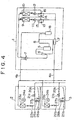
- FIG. 4 is a schematic view of such a multiple-type air conditioner.
- a plurality of, for example, two indoor units 2 and 3 are connected to one outdoor unit 1 via refrigerant pipes 4a and 4b.
- the outdoor unit 1 is provided with a compressor 5, and a four-way directional control valve 7 is connected to a refrigerant gas output end of the compressor 5 via an oil separator 6.
- the oil separator 6 is used for separating refrigerant gas into refrigerant gas and oil.
- the refrigerant gas is sent to the four-way directional control .
- valve 7 and the oil is sent to a suction pipe 8 connected to the suction end of the compressor 5.
- check valves 13 and 14 or electronic expansion valves 15 and 16 are connected to a receiver 17 in common.
- To this receiver 17 are connected the two indoor units 2 and 3 via the refrigerant pipe 4a.
- the other end of the four-way directional control valve 7 is connected to the compressor 5 through an accumulator 18 and the suction pipe 8.
- the two indoor units 2 and 3 are configured so that a strainer 20a, 20b is connected to the refrigerant pipe 4a, to the strainer 20a, 20b are connected an electronic expansion valve 21a, 21b, a distributor 22a, 22b, and an indoor heat exchanger 23a, 23b, and the indoor heat exchanger 23a, 23b is connected to the refrigerant pipe 4b.
- the indoor unit 2, 3 is provided with an air blower (air blowing fan) 24a, 24b, and at the bottom thereof is provided a drain pan 25a, 25b for accumulating water separated by air cooling.
- the water accumulated in this drain pan 25a, 25b is discharged by using a drain pump 26a, 26b, or discharged naturally.
- a float switch 27a, 27b is arranged in the drain pan 25a, 25b.
- the float switch 27a, 27b detects the overflow to stop all units.
- the refrigerant gas discharged from the compressor 5 is separated into refrigerant gas and oil by the oil separator 6, and the oil is returned to the suction pipe 8.
- the refrigerant gas is introduced to the outdoor heat exchangers 9 and 10 through the four-way directional control valve 7, and condensed in the outdoor heat exchangers 9 and 10.
- the refrigerant liquid condensed in the outdoor heat exchangers 9 and 10 passes through the distributors 11 and 12, the check valves 13 and 14, and the receiver 17, respectively, and is introduced to the two indoor units 2 and 3 through the refrigerant pipe 4a.
- the refrigerant liquid passes through the strainer 20a, 20b, electronic expansion valve 21a, 21b, and distributor 22a, 22b, and is introduced to the indoor heat exchanger 23a, 23b, where the refrigerant liquid is evaporated into a gaseous form.
- the refrigerant gas returns to the outdoor unit 1 through the refrigerant pipe 4b. It passes through the four-way directional control valve 7, accumulator 18, and suction pipe 8, and is sucked by the compressor 5 again.
- the indoor heat exchanger 23a, 23b in the indoor unit 2, 3 cools air, so that water in the air is separated from air and accumulates as drain water in the drain pan 25a, 25b.
- the water accumulated in this drain pan 25a, 25b is discharged by using the drain pump 26a, 26b, or discharged naturally.
- the drain abnormality is detected by the float switch 27a, 27b.
- a multiple type air conditioner according to the preamble of claim 1 is known from GB-A-2 248 924.
- an object of the present invention is to provide a multiple-type air conditioner in which of the plural indoor units, the indoor units having no abnormality caused by the overflow of drain water can continue to be operated.
- the multiple-type air conditioner comprises the features of claim 1.
- the water level detection switch detects this fact and generates an abnormality signal.
- the air blowing fan of the indoor unit in which abnormality occurs is stopped, the electronic expansion valve is fully closed, and it is determined whether or not the detection temperature of the temperature sensor of the indoor unit in which abnormality occurs increases. If this temperature increases, the operation of other indoor units is continued, and if this temperature does not increase, the operation of all the indoor units is stopped.
- the indoor units having no abnormality caused by the overflow of drain water can continue to be operated.
- FIG. 1 is a schematic view showing one embodiment of a multiple-type air conditioner in accordance with the present invention.
- FIG. 2 is a block diagram of a control system for the air conditioner.
- FIG. 3 is an abnormality control flowchart for the air conditioner.
- FIG. 4 is a schematic view of a conventional multiple-type air conditioner.
- FIG. 5 is an abnormality control flowchart for the conventional air conditioner.
- FIG. 1 is a schematic view of a multiple-type air conditioner.
- the indoor heat exchanger 23a, 23b is provided with a thermistor 30a, 30b as a temperature sensor.
- the thermistor 30a, 30b senses the temperature of the indoor heat exchanger 23a, 23b, and generates a signal according to the temperature of the indoor heat exchanger 23a, 23b.
- FIG. 2 is a block diagram of a control system.
- This control system is provided with an abnormality stop means 31, which receives an abnormality signal generated from the float switch 27a, 27b serving as a water level detection switch.
- This abnormality stop means 31 has the following function: It is determined whether or not an abnormality signal is generated from the float switches 27a and 27b. If drain water overflow abnormality occurs, this means 31 stops the air blower 24a, 24b of the indoor unit 2, 3 in which abnormality occurs, and fully closes the electronic expansion valve 21a, 21b.
- An operability determination means 32 has the following function: When receiving information about the occurrence of drain water overflow abnormality from the abnormality stop, means 31, the operability determination means 32 judges the operation state of the compressor 5 of the outdoor unit 1 through an output means 33. If the compressor 5 is in operation, it is determined whether or not the detection temperature of the thermistor 30a, 30b of the indoor unit 2, 3, that is, the temperature of the indoor heat exchanger 23a, 23b increases. If the detection temperature increases, the operation of the other indoor unit 3, 2 is continued. If the temperature of the indoor heat exchanger 23a, 23b does not increase, the operation of all the indoor units 2 and 3 is stopped.
- this operability determination means 32 has a restart determination means 34.
- This restart determination means 34 has the following function: When the compressor 5, which has been stopped by the occurrence of drain water overflow abnormality, is restarted, this restart determination means 34 determines whether or not the temperature of the indoor heat exchanger 23a, 23b detected by the thermistor 30a, 30b decreases. If the temperature of the indoor heat exchanger 23a, 23b does not decrease, the operation of the other indoor unit 3, 2 is continued. If the temperature of the indoor heat exchanger 23a, 23b decreases, the operation of all the indoor units 2 and 3 is stopped.
- the refrigerant gas discharged from the compressor 5 is separated into refrigerant gas and oil by the oil separator 6, as mentioned before, and the separated refrigerant gas is introduced to the outdoor heat exchangers 9 and 10 through the four-way directional control valve 7, and condensed in the outdoor heat exchangers 9 and 10.
- the condensed refrigerant liquid passes through the distributors 11 and 12, the check valves 13 and 14, and the receiver 17, respectively, and is introduced to the two indoor units 2 and 3 through the refrigerant pipe 4a.
- the refrigerant liquid passes through the strainer 20a, 20b, electronic expansion valve 21a, 21b, and distributor 22a, 22b, and is introduced to the indoor heat exchanger 23a, 23b, where the refrigerant liquid is evaporated into a gaseous form.
- the refrigerant gas returns to the outdoor unit 1 through the refrigerant pipe 4b. It passes through the four-way directional control valve 7, accumulator 18, and suction pipe 8, and is sucked by the compressor 5 again.
- the indoor heat exchanger 23a, 23b in the indoor unit 2, 3 cools air, so that water in the air is separated from air and accumulates as drain water in the drain pan 25a, 25b.
- the water accumulated in this drain pan 25a, 25b is discharged by using the drain pump 26a, 26b, or discharged naturally.
- drain water overflow abnormality signal is generated.
- the abnormality stop means 31 determines in Step #1 whether or not an abnormality signal is generated from the float switches 27a and 27b each.
- the abnormality stop means 31 stops, in Step #2, the operation of the air blower 24a, 24b of the indoor unit 2, 3 in which the abnormality occurs. For example, if an abnormality signal is generated from the float switch 27a, the abnormality stop means 31 stops the operation of the air blower 24a of the indoor unit 2, and, in the next step #3, fully closes the electronic expansion valve 21a. (Hereinafter, the case where drain water overflow abnormality occurs in the indoor unit 2 will be explained.)
- the operability determination means 32 judges, in Step #4, the operation state of the compressor 5 of the outdoor unit 1 through an output means 33.
- Step #5 receiving the detection temperature of the thermistor 30a of the indoor unit 2 in which abnormality occurs, it determines whether or not the temperature of the indoor heat exchanger 23a increases.
- the operability determination means 32 judges that there is no possibility of an increase in drain water of the indoor heat exchanger 23a since the cooling operation is stopped because the electronic expansion valve 21a of the indoor unit 2 in which abnormality occurs is closed. Then, the operability determination means 32 proceeds to Step #6 to stop the operation of only the indoor unit 2 in which abnormality occurs, and continue the operation of the other indoor unit 3.
- Step #5 If it is decided in the above step #5 that the temperature of the indoor heat exchanger 23a of the indoor unit 2 in which abnormality occurs does not increase, the operability determination means 32 proceeds to Step #7 to stop all the indoor units 2 and 3, since the electronic expansion valve 21a is not fully closed, so that there is a possibility that the drain water increases and overflows if the operation is continued.
- the restart determination means 34 waits for the next restart of the compressor 5 in Step #8. In the next step #9, the restart determination means 34 takes in the detection temperature of the thermistor 30a, and determines whether or not the temperature of the indoor heat exchanger 23a of the indoor unit 2 in which abnormality occurs decreases.
- the restart determination means 34 proceeds to Step #10 to stop the operation of the indoor unit 2 in which abnormality occurs and continue the operation of the other indoor unit 3.
- the operability determination means 32 proceeds to Step #11 to stop the operation of all the indoor units 2 and 3.
- the air blower 24a of the indoor unit 2 in which abnormality occurs is stopped, the electronic expansion switch 21a is fully closed, and it is determined from the detection temperature of the thermistor 30a of the indoor unit 2 in which abnormality occurs whether or not the temperature of the indoor heat exchanger 23a increases. If this temperature increases, the operation of the other indoor unit 3 is continued, and if this temperature does not increase, the operation of all the indoor units 2 and 3 is stopped. When the compressor 5, which has been stopped by the occurrence of abnormality, is restarted, it is determined whether or not the temperature of the indoor heat exchanger 23a decreases.
- the indoor unit 3 having no drain abnormality display can be used.
- drain abnormality occurs in two or more indoor units, the operation is the same except that the operation of all the indoor units in which drain abnormality occurs is stopped and the operation of the remaining indoor units is continued.
- the temperature sensor for detecting the temperature of the indoor heat exchanger 23a, 23b is not limited to the thermistor 30a, 30b, and other temperature detecting elements may be used.
- a multiple-type air conditioner in which, of a plurality of indoor units, the indoor units which have no abnormality caused by the overflow of drain water can continue to be operated.
Landscapes
- Engineering & Computer Science (AREA)
- Chemical & Material Sciences (AREA)
- Combustion & Propulsion (AREA)
- Mechanical Engineering (AREA)
- General Engineering & Computer Science (AREA)
- Air Conditioning Control Device (AREA)
- Compression-Type Refrigeration Machines With Reversible Cycles (AREA)
Abstract
Claims (4)
- Appareil de conditionnement d'air à fonctions multiples comprenant une unité extérieure (1) ayant une entrée réfrigérante (4b) et une sortie réfrigérante (4a), et une pluralité d'unités intérieures (2, 3), chaque unité d'intérieur incluant :Un robinet de détente électriquement contrôlé (21a, 21b) et un échangeur thermique (23a, 23b) couplé en série entre ladite entrée réfrigérante et ladite sortie réfrigérante ;Un ventilateur (24a, 24b) ;Un plateau de dégivrage (25a, 25b) pour recevoir et déverser l'eau de drainage générée par l'échangeur thermique ;Un détecteur de température (30a, 30b) sur l'échangeur thermique ; etUn interrupteur de détection du niveau d'eau (27a, 27b) générant un signal d'anomalie si le niveau d'eau dans le plateau de dégivrage atteint un niveau prédéterminé ;L'appareil de conditionnement d'air étant caractérisé en ce qu'il comprend de plusDes moyens d'arrêt d'anomalie (31) couplés à l'interrupteur de chaque unité intérieure et réceptifs à un signal d'anomalie dudit interrupteur d'une dite unité intérieure permettant, la fermeture du robinet de détente, mais aussi l'arrêt du ventilateur dans ladite unité intérieure dans laquelle l'anomalie apparaít ; etDes moyens de détermination du mode de fonctionnement (32) couplés à chaque dit détecteur de température et disposés pour permettre, en réponse audit signal d'anomalie, le fonctionnement de toutes les autres unités intérieures si la température détectée par le détecteur de ladite unité intérieure, dans laquelle l'anomalie apparaít, augmente, et pour arrêter le fonctionnement de toutes les autres unités intérieures si la température détectée par le détecteur de ladite unité intérieure, dans laquelle l'anomalie apparaít, diminue.
- Appareil de conditionnement d'air selon la revendication 1, caractérisé en ce que les moyens de détermination du mode de fonctionnement comprennent de plus des moyens de détermination de la remise en marche (34), déterminant en fonction dudit signal d'anomalie, si un compresseur (5) de l'unité extérieure est ou n'est pas opérationnel.
- Appareil de conditionnement d'air selon la revendication 2, caractérisé en ce que les moyens de détermination du mode de fonctionnement sont disposés pour répondre auxdits moyens de détermination de la remise en marche en stoppant le fonctionnement de toutes les autres unités intérieures si le compresseur est déterminé pour être opérationnel et la température détectée par le détecteur de température de ladite unité, dans laquelle l'anomalie apparaít, n'augmente pas.
- Appareil de conditionnement d'air selon l'une des revendications 2 ou 3, caractérisé en ce que, si le compresseur est déterminé pour être inopérationnel en fonction dudit signal d'anomalie, lesdits moyens de détermination de remise en marche sont arrangés pour détecter la mise en marche du compresseur, et lesdits moyens de détermination du mode de fonctionnement sont arrangés pour répondre également en permettant le fonctionnement de toutes les autres unités intérieures si la température détectée par le détecteur de la température de ladite unité, dans laquelle l'anomalie apparaít, ne diminue pas.
Applications Claiming Priority (4)
| Application Number | Priority Date | Filing Date | Title |
|---|---|---|---|
| JP10019096A JP3776502B2 (ja) | 1996-04-22 | 1996-04-22 | マルチ形空気調和機 |
| JP10019096 | 1996-04-22 | ||
| JP100190/96 | 1996-04-22 | ||
| PCT/JP1997/001361 WO1997040326A1 (fr) | 1996-04-22 | 1997-04-21 | Appareil de conditionnement d'air a fonctions multiples |
Publications (3)
| Publication Number | Publication Date |
|---|---|
| EP0834708A1 EP0834708A1 (fr) | 1998-04-08 |
| EP0834708A4 EP0834708A4 (fr) | 1998-12-16 |
| EP0834708B1 true EP0834708B1 (fr) | 2002-11-06 |
Family
ID=14267389
Family Applications (1)
| Application Number | Title | Priority Date | Filing Date |
|---|---|---|---|
| EP97917445A Expired - Lifetime EP0834708B1 (fr) | 1996-04-22 | 1997-04-21 | Appareil de conditionnement d'air a fonctions multiples |
Country Status (6)
| Country | Link |
|---|---|
| EP (1) | EP0834708B1 (fr) |
| JP (1) | JP3776502B2 (fr) |
| CN (1) | CN1100240C (fr) |
| ID (1) | ID16639A (fr) |
| TW (1) | TW323329B (fr) |
| WO (1) | WO1997040326A1 (fr) |
Cited By (2)
| Publication number | Priority date | Publication date | Assignee | Title |
|---|---|---|---|---|
| CN109708248A (zh) * | 2018-12-29 | 2019-05-03 | 广东美的暖通设备有限公司 | 空调系统的阀体失效检测方法及空调系统 |
| EP4692664A1 (fr) * | 2024-08-05 | 2026-02-11 | Guangdong Carrier Heating, Ventilation And Air Conditioning Co., Ltd. | Procédé de commande et dispositif de commande pour empêcher une fausse alarme d'un commutateur de niveau d'eau anti-débordement de climatiseur |
Families Citing this family (7)
| Publication number | Priority date | Publication date | Assignee | Title |
|---|---|---|---|---|
| JP4485863B2 (ja) * | 2004-07-09 | 2010-06-23 | 株式会社神戸製鋼所 | 圧縮機 |
| CN100465535C (zh) * | 2004-11-13 | 2009-03-04 | 珠海格力电器股份有限公司 | 一种定频多联空调机组 |
| JP5262398B2 (ja) * | 2008-07-28 | 2013-08-14 | ダイキン工業株式会社 | ドレン排水方法、空気調和装置および空気調和システム、ドレンソケット |
| JP5474048B2 (ja) * | 2009-03-23 | 2014-04-16 | 三菱電機株式会社 | 空気調和装置 |
| CN104033992A (zh) * | 2014-06-06 | 2014-09-10 | 广东美的暖通设备有限公司 | 多联机空调故障处理方法及空调器 |
| CN113531773B (zh) * | 2021-06-18 | 2022-11-15 | 宁波奥克斯电气股份有限公司 | 一种多联空调故障检测方法、装置及多联空调 |
| WO2025032755A1 (fr) * | 2023-08-09 | 2025-02-13 | 三菱電機株式会社 | Système de climatisation |
Family Cites Families (3)
| Publication number | Priority date | Publication date | Assignee | Title |
|---|---|---|---|---|
| JPH0726754B2 (ja) * | 1986-10-20 | 1995-03-29 | 三洋電機株式会社 | 冷凍装置 |
| JP3055163B2 (ja) * | 1990-10-16 | 2000-06-26 | 東芝キヤリア株式会社 | 空気調和機 |
| JPH07229634A (ja) * | 1994-02-16 | 1995-08-29 | Matsushita Seiko Co Ltd | 分離型空気調和機のドレン水漏れ防止装置 |
-
1996
- 1996-04-22 JP JP10019096A patent/JP3776502B2/ja not_active Expired - Lifetime
-
1997
- 1997-04-21 CN CN97190381A patent/CN1100240C/zh not_active Expired - Lifetime
- 1997-04-21 EP EP97917445A patent/EP0834708B1/fr not_active Expired - Lifetime
- 1997-04-21 TW TW086105144A patent/TW323329B/zh active
- 1997-04-21 WO PCT/JP1997/001361 patent/WO1997040326A1/fr not_active Ceased
- 1997-04-22 ID IDP971332A patent/ID16639A/id unknown
Cited By (2)
| Publication number | Priority date | Publication date | Assignee | Title |
|---|---|---|---|---|
| CN109708248A (zh) * | 2018-12-29 | 2019-05-03 | 广东美的暖通设备有限公司 | 空调系统的阀体失效检测方法及空调系统 |
| EP4692664A1 (fr) * | 2024-08-05 | 2026-02-11 | Guangdong Carrier Heating, Ventilation And Air Conditioning Co., Ltd. | Procédé de commande et dispositif de commande pour empêcher une fausse alarme d'un commutateur de niveau d'eau anti-débordement de climatiseur |
Also Published As
| Publication number | Publication date |
|---|---|
| EP0834708A1 (fr) | 1998-04-08 |
| WO1997040326A1 (fr) | 1997-10-30 |
| HK1009842A1 (en) | 1999-09-17 |
| ID16639A (id) | 1997-10-23 |
| CN1100240C (zh) | 2003-01-29 |
| JP3776502B2 (ja) | 2006-05-17 |
| JPH09287802A (ja) | 1997-11-04 |
| EP0834708A4 (fr) | 1998-12-16 |
| CN1189212A (zh) | 1998-07-29 |
| TW323329B (fr) | 1997-12-21 |
Similar Documents
| Publication | Publication Date | Title |
|---|---|---|
| KR100664056B1 (ko) | 멀티형 공기조화기의 고장유무 판별장치 및 방법 | |
| EP2204621B1 (fr) | Climatiseur et procédé de détection de dysfonctionnements correspondant | |
| EP1657505B1 (fr) | Système et procédé pour déterminer l'obstruction d'un tube d'un systéme de conditionnement d'air à unitée multiple | |
| US7343750B2 (en) | Diagnosing a loss of refrigerant charge in a refrigerant system | |
| EP0834708B1 (fr) | Appareil de conditionnement d'air a fonctions multiples | |
| US5297396A (en) | Air conditioning apparatus having a plurality of indoor units connected to an outdoor unit | |
| JP2003097443A (ja) | 圧縮機および冷凍装置 | |
| US7765812B2 (en) | System for detecting mis-connected state between communication lines for multi-type air conditioner and method thereof | |
| JP3290251B2 (ja) | 空気調和機 | |
| JP3191719B2 (ja) | 冷凍装置の油戻し運転制御装置 | |
| HK1009842B (en) | Multi-type air-conditioner | |
| JP3302138B2 (ja) | 空気調和機 | |
| KR20100069404A (ko) | 공기조화기 및 그 제어 방법 | |
| KR20190083738A (ko) | 공기 조화기 및 그의 제어 방법 | |
| KR20030075391A (ko) | 에어컨 드레인 팬의 과수위 경보장치 | |
| KR20000073050A (ko) | 공기조화기의 저압측 막힘 판단방법 | |
| KR20000073043A (ko) | 공기조화기의 송풍팬 고장감지방법 | |
| JP2687727B2 (ja) | 冷凍装置の圧縮機保護装置 | |
| JPH0473566A (ja) | 冷凍装置の運転制御装置 | |
| JPH0593562A (ja) | 空気調和装置 | |
| JPH03267657A (ja) | 多室型空気調和機 | |
| KR20010001610A (ko) | 멀티형 공조기의 오결선 검지방법 | |
| JPH0783483A (ja) | 分離型空気調和機 | |
| JPH01225852A (ja) | 空気調和装置の高圧制御装置 | |
| KR100619748B1 (ko) | 오일회수 운전시점 산출기능을 구비한 멀티형 공기조화기및 멀티형 공기조화기의 오일회수 운전시점 산출방법 |
Legal Events
| Date | Code | Title | Description |
|---|---|---|---|
| PUAI | Public reference made under article 153(3) epc to a published international application that has entered the european phase |
Free format text: ORIGINAL CODE: 0009012 |
|
| 17P | Request for examination filed |
Effective date: 19980114 |
|
| AK | Designated contracting states |
Kind code of ref document: A1 Designated state(s): GB GR IT |
|
| A4 | Supplementary search report drawn up and despatched |
Effective date: 19981104 |
|
| AK | Designated contracting states |
Kind code of ref document: A4 Designated state(s): GB GR IT |
|
| 17Q | First examination report despatched |
Effective date: 20010522 |
|
| GRAG | Despatch of communication of intention to grant |
Free format text: ORIGINAL CODE: EPIDOS AGRA |
|
| GRAG | Despatch of communication of intention to grant |
Free format text: ORIGINAL CODE: EPIDOS AGRA |
|
| GRAH | Despatch of communication of intention to grant a patent |
Free format text: ORIGINAL CODE: EPIDOS IGRA |
|
| GRAH | Despatch of communication of intention to grant a patent |
Free format text: ORIGINAL CODE: EPIDOS IGRA |
|
| GRAA | (expected) grant |
Free format text: ORIGINAL CODE: 0009210 |
|
| AK | Designated contracting states |
Kind code of ref document: B1 Designated state(s): GB GR IT |
|
| REG | Reference to a national code |
Ref country code: GB Ref legal event code: FG4D |
|
| PGFP | Annual fee paid to national office [announced via postgrant information from national office to epo] |
Ref country code: GB Payment date: 20030307 Year of fee payment: 7 |
|
| REG | Reference to a national code |
Ref country code: GR Ref legal event code: EP Ref document number: 20030400451 Country of ref document: GR |
|
| PLBE | No opposition filed within time limit |
Free format text: ORIGINAL CODE: 0009261 |
|
| STAA | Information on the status of an ep patent application or granted ep patent |
Free format text: STATUS: NO OPPOSITION FILED WITHIN TIME LIMIT |
|
| 26N | No opposition filed |
Effective date: 20030807 |
|
| PG25 | Lapsed in a contracting state [announced via postgrant information from national office to epo] |
Ref country code: GB Free format text: LAPSE BECAUSE OF NON-PAYMENT OF DUE FEES Effective date: 20040421 |
|
| GBPC | Gb: european patent ceased through non-payment of renewal fee |
Effective date: 20040421 |
|
| PGFP | Annual fee paid to national office [announced via postgrant information from national office to epo] |
Ref country code: GR Payment date: 20050311 Year of fee payment: 9 |
|
| PG25 | Lapsed in a contracting state [announced via postgrant information from national office to epo] |
Ref country code: GR Free format text: LAPSE BECAUSE OF NON-PAYMENT OF DUE FEES Effective date: 20061102 |
|
| PGFP | Annual fee paid to national office [announced via postgrant information from national office to epo] |
Ref country code: IT Payment date: 20160418 Year of fee payment: 20 |