EP0834730A2 - Zerstörungsfreies diagnostisches Verfahren und Gerät - Google Patents
Zerstörungsfreies diagnostisches Verfahren und Gerät Download PDFInfo
- Publication number
- EP0834730A2 EP0834730A2 EP97116819A EP97116819A EP0834730A2 EP 0834730 A2 EP0834730 A2 EP 0834730A2 EP 97116819 A EP97116819 A EP 97116819A EP 97116819 A EP97116819 A EP 97116819A EP 0834730 A2 EP0834730 A2 EP 0834730A2
- Authority
- EP
- European Patent Office
- Prior art keywords
- detector
- light
- reduction ratio
- weight reduction
- measured
- Prior art date
- Legal status (The legal status is an assumption and is not a legal conclusion. Google has not performed a legal analysis and makes no representation as to the accuracy of the status listed.)
- Withdrawn
Links
Images

Classifications
-
- G—PHYSICS
- G01—MEASURING; TESTING
- G01N—INVESTIGATING OR ANALYSING MATERIALS BY DETERMINING THEIR CHEMICAL OR PHYSICAL PROPERTIES
- G01N21/00—Investigating or analysing materials by the use of optical means, i.e. using sub-millimetre waves, infrared, visible or ultraviolet light
- G01N21/17—Systems in which incident light is modified in accordance with the properties of the material investigated
- G01N21/25—Colour; Spectral properties, i.e. comparison of effect of material on the light at two or more different wavelengths or wavelength bands
- G01N21/27—Colour; Spectral properties, i.e. comparison of effect of material on the light at two or more different wavelengths or wavelength bands using photo-electric detection ; circuits for computing concentration
-
- G—PHYSICS
- G01—MEASURING; TESTING
- G01N—INVESTIGATING OR ANALYSING MATERIALS BY DETERMINING THEIR CHEMICAL OR PHYSICAL PROPERTIES
- G01N33/00—Investigating or analysing materials by specific methods not covered by groups G01N1/00 - G01N31/00
- G01N33/26—Oils; Viscous liquids; Paints; Inks
- G01N33/28—Oils, i.e. hydrocarbon liquids
- G01N33/2888—Lubricating oil characteristics, e.g. deterioration
-
- G—PHYSICS
- G01—MEASURING; TESTING
- G01N—INVESTIGATING OR ANALYSING MATERIALS BY DETERMINING THEIR CHEMICAL OR PHYSICAL PROPERTIES
- G01N21/00—Investigating or analysing materials by the use of optical means, i.e. using sub-millimetre waves, infrared, visible or ultraviolet light
- G01N21/17—Systems in which incident light is modified in accordance with the properties of the material investigated
- G01N21/25—Colour; Spectral properties, i.e. comparison of effect of material on the light at two or more different wavelengths or wavelength bands
- G01N21/31—Investigating relative effect of material at wavelengths characteristic of specific elements or molecules, e.g. atomic absorption spectrometry
- G01N21/314—Investigating relative effect of material at wavelengths characteristic of specific elements or molecules, e.g. atomic absorption spectrometry with comparison of measurements at specific and non-specific wavelengths
- G01N21/3151—Investigating relative effect of material at wavelengths characteristic of specific elements or molecules, e.g. atomic absorption spectrometry with comparison of measurements at specific and non-specific wavelengths using two sources of radiation of different wavelengths
-
- G—PHYSICS
- G01—MEASURING; TESTING
- G01N—INVESTIGATING OR ANALYSING MATERIALS BY DETERMINING THEIR CHEMICAL OR PHYSICAL PROPERTIES
- G01N21/00—Investigating or analysing materials by the use of optical means, i.e. using sub-millimetre waves, infrared, visible or ultraviolet light
- G01N21/17—Systems in which incident light is modified in accordance with the properties of the material investigated
- G01N21/25—Colour; Spectral properties, i.e. comparison of effect of material on the light at two or more different wavelengths or wavelength bands
- G01N21/31—Investigating relative effect of material at wavelengths characteristic of specific elements or molecules, e.g. atomic absorption spectrometry
- G01N21/35—Investigating relative effect of material at wavelengths characteristic of specific elements or molecules, e.g. atomic absorption spectrometry using infrared light
-
- G—PHYSICS
- G01—MEASURING; TESTING
- G01N—INVESTIGATING OR ANALYSING MATERIALS BY DETERMINING THEIR CHEMICAL OR PHYSICAL PROPERTIES
- G01N21/00—Investigating or analysing materials by the use of optical means, i.e. using sub-millimetre waves, infrared, visible or ultraviolet light
- G01N21/17—Systems in which incident light is modified in accordance with the properties of the material investigated
- G01N21/25—Colour; Spectral properties, i.e. comparison of effect of material on the light at two or more different wavelengths or wavelength bands
- G01N21/31—Investigating relative effect of material at wavelengths characteristic of specific elements or molecules, e.g. atomic absorption spectrometry
- G01N21/35—Investigating relative effect of material at wavelengths characteristic of specific elements or molecules, e.g. atomic absorption spectrometry using infrared light
- G01N21/3563—Investigating relative effect of material at wavelengths characteristic of specific elements or molecules, e.g. atomic absorption spectrometry using infrared light for analysing solids; Preparation of samples therefor
-
- G—PHYSICS
- G01—MEASURING; TESTING
- G01N—INVESTIGATING OR ANALYSING MATERIALS BY DETERMINING THEIR CHEMICAL OR PHYSICAL PROPERTIES
- G01N21/00—Investigating or analysing materials by the use of optical means, i.e. using sub-millimetre waves, infrared, visible or ultraviolet light
- G01N21/17—Systems in which incident light is modified in accordance with the properties of the material investigated
- G01N21/25—Colour; Spectral properties, i.e. comparison of effect of material on the light at two or more different wavelengths or wavelength bands
- G01N21/31—Investigating relative effect of material at wavelengths characteristic of specific elements or molecules, e.g. atomic absorption spectrometry
- G01N21/35—Investigating relative effect of material at wavelengths characteristic of specific elements or molecules, e.g. atomic absorption spectrometry using infrared light
- G01N21/3577—Investigating relative effect of material at wavelengths characteristic of specific elements or molecules, e.g. atomic absorption spectrometry using infrared light for analysing liquids, e.g. polluted water
Definitions
- the present invention relates to a nondestructive diagnostic method and a nondestructive diagnostic apparatus which can nondestructively and optically diagnose weight reduction ratio of an insulating material, a structural material, a lubricating oil, or the like which is used in equipment irrespective of liquid or solid without stopping the operation of the working equipment.
- Japanese Patent Laid-Open Publication No. Sho 64-84162 discloses a diagnostic apparatus in which an irradiated light beam led from a white standard light source by an optical fiber is reflected by a sensor unit made of a material same as the insulating material.
- the reflected light beam is detected via a light receiving optical fiber, and a color specification arithmetic operation is executed by using chromaticity or a difference in chromaticity based on the L*a*b* color specification system.
- L* is a lightness index showing lightness and a* and b* are called chromatic indices showing chromaticity (hue and saturation).
- the conventional technique cannot diagnose the weight reduction ratio of a material.
- An object of the present invention is to provide a nondestructive diagnostic method and a nondestructive diagnostic apparatus which can solve the above problems and can optically and nondestructively diagnose the weight reduction ratio of an insulating material or a structural material which is used for equipment irrespective of liquid or solid without stopping the operation of the working equipment.
- the inventors of the present invention examined the relation between reduction in weight of a resin or oil and optical physical properties, and found out the nondestructive diagnostic method and the nondestructive diagnostic apparatus of the invention which can accurately determine the weight reduction ratio from change in the intensity of the light beam reflected by the surface of the resin or oil or the intensity of a transmitted light beam in association with thermal deterioration. That is, the gist of the invention is as follows.
- a LED a light emitting diode
- a LD a laser diode
- the LED and LD light sources each emitting a light beam having a peak wavelength of 660, 670, 780, 800, 850, 1030, 1300, 1550 nm, or the like are preferred.
- the object to be measured is acrylate resin, polycarbonate resin, mineral oil, or the like which is originally very transparent, light beams at wavelengths of 660, 670, 780, 800, 850 nm, and the like are suitable.
- the object to be measured is alkyd resin or unsaturated polyester resin which is originally colored, epoxy resin which is immediately colored to black, an opaque resin including a pigment or the like, light beams at wavelengths in a near infrared region of 780, 800, 850, 1030, 1300, 1550 nm and the like are suitable.
- the optical fibers are not requested to have high heat resistance.
- Optical fibers made of plastic each having a large diameter can be consequently used, so that it is advantageous in improving light-intercepting efficiency.
- the relation between the preliminarily stored weight reduction ratio of the object to be measured and the reflective absorbance difference at different wavelengths, or the relation between the weight reduction ratio of the object to be measured and a light transmission loss can be obtained by an accelerated deterioration test which is performed as a model.
- the obtained relation diagram is generally called a diagnostic master curve.
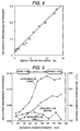
- Figs. 3 and 4 show representative examples.
- the accelerated deterioration test is not especially limited but can be performed by using a conventionally known technique.
- the reflective absorbance shows remarkable increase on the shorter wavelength side in a visible range in association with deterioration as shown in the diagram, it is substantially difficult to keep on measuring the absorbance of a material which is being used until the end of life of equipment in a range shorter than 660 nm due to a limited measurement range of a detector (detector).
- the increase in the reflective absorbance on the shorter wavelength side is mainly due to increase in electron transition absorption loss by a deterioration reaction of thermal oxidation of the material.
- l 1 ⁇ l 2 .
- the reflective absorbance difference DA l at the wavelengths l 1 (nm) and l 2 (nm) is set to a1, a2, and a3 to a material in which deterioration is large, a material in which deterioration is small, and a material in an initial state, respectively, the relation of a1 > a2 > a3 is satisfied.
- a similar relation can be also obtained with respect to the light transmission loss.
- the degree of deterioration is expressed by reduced time ⁇ .
- the reduced time q (h) is defined by an expression (4).
- ⁇ 0 t exp(- ⁇ E / RT) dt
- DE apparent activation energy (J/mol) of the thermal deterioration
- R is a gas constant (J/K/mol)
- T an absolute value (K) of thermal deterioration
- t deterioration time (h).
- DE of resin or oil can be easily calculated by Arrenius plotting the change in the reflective absorbance difference or the change in light transmission loss at few kinds of deterioration temperatures.
- average temperature T when the equipment is used can be also estimated by using the expression (4). This will be described by following embodiments of the present invention.
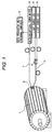
- Fig. 1 shows an example of diagnosing the weight reduction ratio of epoxy resin fixing a rotor bar by measuring light beams reflected from a surface of a rotor 1 of a rotating machine. First, quantities of reference lights at different wavelengths of two light source LEDs 3 and 4 are measured. In the embodiment, l 1 is set to 670 nm and l 2 is set to 1300 nm.
- a monochromatic light beam at the peak wavelength l 1 generated from the light source LED 3 passes through an irradiation optical fiber 5 via an optical coupler 6 and is irradiated to a standard white sheet from a probe 2.
- alumina oxide, a white regular sheet, or the like can be also used.
- a chrome plated metal plate or the like can be also used without any problem.
- the reflected light beam is transferred to a detector (a photocell or an optical power meter) 8 via a light receiving optical fiber 7.
- a quantity I 1 of the reference light beam at the peak wavelength l 1 is measured and is stored into a data processing unit (personal computer) 9.
- a similar operation is performed by using a monochromatic light beam at the peak wavelength l 2 generated from the light source LED 4 and a quantity I 2 of the reference light beam at the peak wavelength l 2 is stored into the data processing unit (personal computer) 9. Subsequently, the quantity of the reflected light beam from the surface of the rotor 1 of the rotating machine is measured.
- the monochromatic light beams from the light source LEDs 3 and 4 are used and irradiated to the surface of the rotor 1 of the rotating machine and quantities I 1' and I 2' of the reflected light beams are measured.
- the difference in absorbance corresponding to the weight reduction ratio of the resin as shown in Fig. 4 is preliminarily stored as a master curve, and the weight reduction ratio of the rotor 1 of the rotating machine is determined by comparing the stored function value with the actually measured reflective absorbance difference DAl and is outputted as a measurement result to an external printer or the like (not shown).
- Fig. 5 shows results of continuously measuring the reflective absorbance difference from the intake side to the exhaust side of the rotor with respect to three rotors.
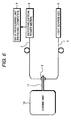
- Fig. 6 shows an example of nondestructively diagnosing the weight reduction ratio of a lubricating oil by measuring the quantity of a light beam transmitted the lubricating oil of an engine unit 10 by using a flow cell 11.
- a quantify of a reference light beam from the light source LED 3 is measured in a manner similar to the first embodiment.
- l 1 is set to 850 nm.
- a monochromatic light beam at the peak wavelength l 1 generated from the light source LED 3 passes through the irradiation optical fiber 5 and is transferred to the light receiving optical fiber 7 via two probes 2 which are closely arranged so as to face each other.
- the transferred light beam is transmitted to the detector (optical power meter) 8, a quantity I 1 of the reference light beam at the peak wavelength l 1 is measured and is stored into the data processing unit (personal computer) 9. Subsequently, a quantity of a light beam transmitted the lubricating oil of the engine unit 10 is measured.
- a light transmission loss corresponding to the weight reduction ratio of the resin as shown in Fig. 3 has been preliminarily stored as a master curve in the data processing unit (personal computer) 9.
- the weight reduction ratio of the lubricating oil of the engine unit 10 is determined by comparing the stored function value with the actually measured light transmission loss L l and is outputted as a measurement result to an external printer or the like (not shown). According to the present invention, the weight reduction ratio of the insulating material, structural material, lubricating oil, or the like which is used for equipment can be nondestructively diagnosed without stopping the operation of the working equipment.
Landscapes
- Physics & Mathematics (AREA)
- Spectroscopy & Molecular Physics (AREA)
- Health & Medical Sciences (AREA)
- Chemical & Material Sciences (AREA)
- Life Sciences & Earth Sciences (AREA)
- Pathology (AREA)
- Biochemistry (AREA)
- General Health & Medical Sciences (AREA)
- General Physics & Mathematics (AREA)
- Immunology (AREA)
- Analytical Chemistry (AREA)
- Engineering & Computer Science (AREA)
- Chemical Kinetics & Catalysis (AREA)
- General Chemical & Material Sciences (AREA)
- Oil, Petroleum & Natural Gas (AREA)
- Food Science & Technology (AREA)
- Medicinal Chemistry (AREA)
- Toxicology (AREA)
- Mathematical Physics (AREA)
- Theoretical Computer Science (AREA)
- Investigating Or Analysing Materials By Optical Means (AREA)
Applications Claiming Priority (2)
| Application Number | Priority Date | Filing Date | Title |
|---|---|---|---|
| JP26403896A JPH10111241A (ja) | 1996-10-04 | 1996-10-04 | 非破壊診断方法および非破壊診断装置 |
| JP264038/96 | 1996-10-04 |
Publications (2)
| Publication Number | Publication Date |
|---|---|
| EP0834730A2 true EP0834730A2 (de) | 1998-04-08 |
| EP0834730A3 EP0834730A3 (de) | 1998-09-16 |
Family
ID=17397694
Family Applications (1)
| Application Number | Title | Priority Date | Filing Date |
|---|---|---|---|
| EP97116819A Withdrawn EP0834730A3 (de) | 1996-10-04 | 1997-09-26 | Zerstörungsfreies diagnostisches Verfahren und Gerät |
Country Status (4)
| Country | Link |
|---|---|
| US (1) | US6061139A (de) |
| EP (1) | EP0834730A3 (de) |
| JP (1) | JPH10111241A (de) |
| KR (1) | KR100517104B1 (de) |
Cited By (3)
| Publication number | Priority date | Publication date | Assignee | Title |
|---|---|---|---|---|
| WO2000028303A1 (en) * | 1998-11-05 | 2000-05-18 | Hitachi, Ltd. | Method for measuring water content, device for measuring water content, and method for producing electronic device |
| CN103210299A (zh) * | 2010-09-07 | 2013-07-17 | 特克尼克基金会 | 用于确定润滑油衰变状态的方法和装置 |
| ITAN20120140A1 (it) * | 2012-10-24 | 2014-04-25 | Tognella S P A Flli | Dispositivo e procedimento per misurare la concentrazione di almeno un contaminante presente in un fluido |
Families Citing this family (12)
| Publication number | Priority date | Publication date | Assignee | Title |
|---|---|---|---|---|
| MXPA02010596A (es) | 2000-04-26 | 2003-03-10 | Glaxo Group Ltd | Metodo y aparato para el analisis espectroscopico in -situ. |
| JP2002031599A (ja) * | 2000-07-13 | 2002-01-31 | Hitachi Ltd | 劣化診断装置 |
| US6690452B2 (en) * | 2001-04-18 | 2004-02-10 | Paul A. Wilks, Jr. | Monitor having a polymer internal reflective element |
| US6776543B1 (en) * | 2003-02-04 | 2004-08-17 | Hewlett-Packard Development Company, L.P. | Fiber optic print media thickness sensor and method |
| US7502114B2 (en) * | 2004-03-12 | 2009-03-10 | Mks Instruments, Inc. | Ozone concentration sensor |
| RU2329502C1 (ru) * | 2006-11-28 | 2008-07-20 | Государственное научное учреждение "Институт механики металлополимерных систем имени В.А. Белого Национальной академии наук Беларуси" | Способ оперативного контроля работоспособности масла и устройство для его осуществления |
| DE102007042254A1 (de) * | 2007-09-06 | 2009-04-02 | Carl Freudenberg Kg | Messvorrichtung und Verfahren zur Analyse des Schmiermittels eines Lagers |
| KR101356176B1 (ko) * | 2011-08-30 | 2014-01-28 | 한국화학연구원 | 엔진오일열화 감지방법 및 시스템 |
| WO2019055269A1 (en) * | 2017-09-15 | 2019-03-21 | Exxonmobil Research And Engineering Company | ELECTROSTATIC DETECTION OF VARNISH AND PRECURSORS IN LUBRICANTS |
| JP7072433B2 (ja) * | 2018-04-24 | 2022-05-20 | 株式会社Ihiプラント | タンクの液密度測定装置および方法 |
| JP7388886B2 (ja) * | 2019-11-13 | 2023-11-29 | 株式会社日立製作所 | 潤滑油の診断システム |
| JP2025529282A (ja) | 2022-09-06 | 2025-09-04 | アクセス メディカル システムズ,リミティド | アルゴリズム的な逆畳み込み及び計算を通じた干渉型テスト中の光吸収の処理 |
Family Cites Families (8)
| Publication number | Priority date | Publication date | Assignee | Title |
|---|---|---|---|---|
| US5049742A (en) * | 1989-11-16 | 1991-09-17 | Kyodo Oil Technical Research Co., Ltd. | Apparatus for detecting deterioration of engine oil |
| US5138178A (en) * | 1990-12-17 | 1992-08-11 | Xerox Corporation | Photoelectric paper basis weight sensor |
| US5424840A (en) * | 1992-07-21 | 1995-06-13 | The State Of Oregon Acting By And Through The State Board Of Higher Education On Behalf Of Oregon State University | In situ chlorophyl absorption meter |
| US5424542A (en) * | 1993-09-21 | 1995-06-13 | Exxon Research And Engineering Company | Method to optimize process to remove normal paraffins from kerosine |
| JPH07140074A (ja) * | 1993-11-18 | 1995-06-02 | Hitachi Ltd | 機器の劣化監視システム |
| JPH07250443A (ja) * | 1994-03-09 | 1995-09-26 | Hitachi Ltd | 回転電機用巻線及びその製造方法 |
| JPH0815131A (ja) * | 1994-06-29 | 1996-01-19 | Hitachi Ltd | 劣化診断システム |
| JPH09222393A (ja) * | 1996-02-16 | 1997-08-26 | Hitachi Ltd | 劣化度診断装置 |
-
1996
- 1996-10-04 JP JP26403896A patent/JPH10111241A/ja active Pending
-
1997
- 1997-09-26 EP EP97116819A patent/EP0834730A3/de not_active Withdrawn
- 1997-10-02 KR KR1019970050950A patent/KR100517104B1/ko not_active Expired - Fee Related
- 1997-10-03 US US08/943,230 patent/US6061139A/en not_active Expired - Fee Related
Cited By (4)
| Publication number | Priority date | Publication date | Assignee | Title |
|---|---|---|---|---|
| WO2000028303A1 (en) * | 1998-11-05 | 2000-05-18 | Hitachi, Ltd. | Method for measuring water content, device for measuring water content, and method for producing electronic device |
| EP1128178A4 (de) * | 1998-11-05 | 2002-09-18 | Hitachi Ltd | Verfahren zur bestimmung des wassergehalts, vorrichtung zur messung des wassergehalts und verfahren zur herstellung einer elektronischen vorrichtung |
| CN103210299A (zh) * | 2010-09-07 | 2013-07-17 | 特克尼克基金会 | 用于确定润滑油衰变状态的方法和装置 |
| ITAN20120140A1 (it) * | 2012-10-24 | 2014-04-25 | Tognella S P A Flli | Dispositivo e procedimento per misurare la concentrazione di almeno un contaminante presente in un fluido |
Also Published As
| Publication number | Publication date |
|---|---|
| KR100517104B1 (ko) | 2005-11-28 |
| KR19980032519A (ko) | 1998-07-25 |
| JPH10111241A (ja) | 1998-04-28 |
| EP0834730A3 (de) | 1998-09-16 |
| US6061139A (en) | 2000-05-09 |
Similar Documents
| Publication | Publication Date | Title |
|---|---|---|
| US6061139A (en) | Nondestructive diagnostic method and nondestructive diagnostic apparatus | |
| US5032024A (en) | Optical examination apparatus | |
| EP0816830A2 (de) | Vorrichtung und Verfahren zum Nachweis der Beschädigung der Isolierung eines elektrischen Apparates | |
| US7218803B1 (en) | Microsphere probe for optical surface microscopy and method of using the same | |
| GB2158939A (en) | Monitoring condition of surface | |
| JP4710701B2 (ja) | 高分子材料の劣化診断方法および装置 | |
| US20020069021A1 (en) | Automobile oil deterioration diagnosing apparatus | |
| JP3852557B2 (ja) | 膜厚測定方法およびその方法を用いた膜厚センサ | |
| JP3860846B2 (ja) | 材料の劣化度測定システムおよび測定装置 | |
| JPH0815131A (ja) | 劣化診断システム | |
| US20030060984A1 (en) | Automobile oil deterioration diagnosing apparatus | |
| JPH09222393A (ja) | 劣化度診断装置 | |
| JP3440759B2 (ja) | 電気機器の劣化診断方法及び装置 | |
| JP2004077469A (ja) | 材料の劣化度測定システムおよび測定装置 | |
| JPH11248622A (ja) | 尿検査装置 | |
| JPH07140074A (ja) | 機器の劣化監視システム | |
| JP3205212B2 (ja) | 劣化度診断装置 | |
| JP2001307924A (ja) | 油入変圧器の劣化診断装置 | |
| Hale et al. | Demonstration of an optimised evanescent field optical fibre sensor | |
| CN212514275U (zh) | 基于全光纤的原位水质荧光监测系统 | |
| JPH10300670A (ja) | 油入電気機器の劣化診断方法及び劣化診断装置 | |
| JPH10281985A (ja) | 劣化度診断方法 | |
| Takezawa et al. | Development of a portable diagnostic apparatus for coil insulators in low-voltage induction motors | |
| JPS62159027A (ja) | 油の劣化度検出装置 | |
| JP2001027635A (ja) | オイル劣化度診断装置 |
Legal Events
| Date | Code | Title | Description |
|---|---|---|---|
| PUAI | Public reference made under article 153(3) epc to a published international application that has entered the european phase |
Free format text: ORIGINAL CODE: 0009012 |
|
| AK | Designated contracting states |
Kind code of ref document: A2 Designated state(s): DE FR GB |
|
| PUAL | Search report despatched |
Free format text: ORIGINAL CODE: 0009013 |
|
| AK | Designated contracting states |
Kind code of ref document: A3 Designated state(s): AT BE CH DE DK ES FI FR GB GR IE IT LI LU MC NL PT SE |
|
| 17P | Request for examination filed |
Effective date: 19990302 |
|
| AKX | Designation fees paid |
Free format text: DE FR GB |
|
| RBV | Designated contracting states (corrected) |
Designated state(s): DE FR GB |
|
| 17Q | First examination report despatched |
Effective date: 20060922 |
|
| STAA | Information on the status of an ep patent application or granted ep patent |
Free format text: STATUS: THE APPLICATION IS DEEMED TO BE WITHDRAWN |
|
| 18D | Application deemed to be withdrawn |
Effective date: 20070203 |