EP0834743A2 - Dispositif de mesure pour détecter les pressions dynamiques et statiques d'un aéronef - Google Patents
Dispositif de mesure pour détecter les pressions dynamiques et statiques d'un aéronef Download PDFInfo
- Publication number
- EP0834743A2 EP0834743A2 EP97115836A EP97115836A EP0834743A2 EP 0834743 A2 EP0834743 A2 EP 0834743A2 EP 97115836 A EP97115836 A EP 97115836A EP 97115836 A EP97115836 A EP 97115836A EP 0834743 A2 EP0834743 A2 EP 0834743A2
- Authority
- EP
- European Patent Office
- Prior art keywords
- measuring device
- fuselage
- pressure sensors
- tip
- aircraft
- Prior art date
- Legal status (The legal status is an assumption and is not a legal conclusion. Google has not performed a legal analysis and makes no representation as to the accuracy of the status listed.)
- Granted
Links
- 230000003068 static effect Effects 0.000 title claims abstract description 13
- 238000010438 heat treatment Methods 0.000 claims description 35
- 238000011156 evaluation Methods 0.000 claims description 27
- 239000012528 membrane Substances 0.000 claims description 12
- 230000003287 optical effect Effects 0.000 claims description 9
- 125000006850 spacer group Chemical group 0.000 claims description 8
- 238000001514 detection method Methods 0.000 claims description 6
- 239000004809 Teflon Substances 0.000 claims description 3
- 229920006362 Teflon® Polymers 0.000 claims description 3
- 229910010293 ceramic material Inorganic materials 0.000 claims description 3
- 230000003628 erosive effect Effects 0.000 claims description 3
- 239000000463 material Substances 0.000 claims description 3
- 230000002411 adverse Effects 0.000 description 2
- 238000004364 calculation method Methods 0.000 description 2
- 230000007797 corrosion Effects 0.000 description 2
- 238000005260 corrosion Methods 0.000 description 2
- 230000007704 transition Effects 0.000 description 2
- RZVHIXYEVGDQDX-UHFFFAOYSA-N 9,10-anthraquinone Chemical compound C1=CC=C2C(=O)C3=CC=CC=C3C(=O)C2=C1 RZVHIXYEVGDQDX-UHFFFAOYSA-N 0.000 description 1
- 239000006096 absorbing agent Substances 0.000 description 1
- 230000005540 biological transmission Effects 0.000 description 1
- 238000009530 blood pressure measurement Methods 0.000 description 1
- 239000003990 capacitor Substances 0.000 description 1
- 238000006243 chemical reaction Methods 0.000 description 1
- 239000004020 conductor Substances 0.000 description 1
- 238000010276 construction Methods 0.000 description 1
- 230000001419 dependent effect Effects 0.000 description 1
- 238000006073 displacement reaction Methods 0.000 description 1
- 230000003993 interaction Effects 0.000 description 1
- 239000007769 metal material Substances 0.000 description 1
- 230000001105 regulatory effect Effects 0.000 description 1
- 238000000926 separation method Methods 0.000 description 1
Images


Classifications
-
- G—PHYSICS
- G01—MEASURING; TESTING
- G01P—MEASURING LINEAR OR ANGULAR SPEED, ACCELERATION, DECELERATION, OR SHOCK; INDICATING PRESENCE, ABSENCE, OR DIRECTION, OF MOVEMENT
- G01P13/00—Indicating or recording presence, absence, or direction, of movement
- G01P13/02—Indicating direction only, e.g. by weather vane
- G01P13/025—Indicating direction only, e.g. by weather vane indicating air data, i.e. flight variables of an aircraft, e.g. angle of attack, side slip, shear, yaw
-
- G—PHYSICS
- G01—MEASURING; TESTING
- G01P—MEASURING LINEAR OR ANGULAR SPEED, ACCELERATION, DECELERATION, OR SHOCK; INDICATING PRESENCE, ABSENCE, OR DIRECTION, OF MOVEMENT
- G01P5/00—Measuring speed of fluids, e.g. of air stream; Measuring speed of bodies relative to fluids, e.g. of ship, of aircraft
- G01P5/14—Measuring speed of fluids, e.g. of air stream; Measuring speed of bodies relative to fluids, e.g. of ship, of aircraft by measuring differences of pressure in the fluid
- G01P5/16—Measuring speed of fluids, e.g. of air stream; Measuring speed of bodies relative to fluids, e.g. of ship, of aircraft by measuring differences of pressure in the fluid using Pitot tubes, e.g. Machmeter
- G01P5/165—Arrangements or constructions of Pitot tubes
Definitions
- the present invention relates to a measuring device for detection of dynamic and static pressures in an aircraft, in particular one Fighter plane.
- a pitot tube which acts as an external component
- the one in the pitot tube measured pressures provide information about various air data parameters, like altitude and speed.
- Angle of attack or sliding of the aircraft are usually measured with wind vanes.
- the externally arranged pitot tubes or wind vanes have different Disadvantages. For example, it is possible that the measuring device no longer reliable at high angles of attack of the aircraft works or in extreme cases can even become inoperable. A The reason for this arises from the fact that it is at high angles of attack of the aircraft on the pitot tube to large changes in the direction of flow comes relatively to the pressure measurement opening.
- Another Disadvantage of the external arrangement is that the pitot tube and the wind vanes can be detected by radars.
- the aerodynamic flow on the external components Aircraft fuselage adversely affected.
- the invention is the Task to create a measuring device in which the above mentioned disadvantages can be avoided.
- a Measuring device are proposed, even at high angles of attack of the aircraft works safely and reliably.
- the beginning of a measuring device mentioned type proposed that the measuring device a variety of pressure sensors located in the fuselage tip of the aircraft are arranged and that at the fuselage tip a plurality of air inlet openings are provided, which via connecting channels with the Pressure sensors are connected.
- the measuring device designed in this way first of all ensures that on such components that attach externally to the fuselage of the aircraft are dispensed with. According to the present invention all components relevant to the measuring device in the fuselage tip of the aircraft. This advantageously eliminates those components that can be detected by a radar. About that In addition, the flow conditions on the fuselage of the Aircraft improved because aerodynamically unfavorable components now are integrated into the fuselage tip.
- the measuring device according to the invention can both with manned can also be used with unmanned aerial vehicles.
- the air inlet openings over the circumference and / or are advantageous offset along the longitudinal direction of the fuselage tip in the wall of the Fuselage tip provided. Due to the geometrically sensible arrangement the air inlet openings at the fuselage tip is achieved that the Back pressure and static pressures even with large changes in the direction of flow safe and relative to the reference axes of the air inlet openings can be reliably detected.
- the Pressure sensors arranged in a circular disk-shaped magazine.
- the pressure sensors can be cylindrical.
- each pressure sensor is via one or more connecting channels connected to one of the air inlet openings.
- the connecting channels can be used as connecting pipes and / or bores.
- the pressure sensors comprise a basic body with at least one C R electrode and one C P electrode, a spacer as well as a membrane having a counter electrode.
- the base body, the spacer and the membrane are preferably formed from a ceramic material.
- the pressure sensor according to the invention converts a pressure which acts on the membrane into an electrical signal which can be processed further accordingly.
- the invention provided that the pressure sensors with an electrical evaluation unit are connected.
- This electrical evaluation unit advantageously has a redundant one Structure on and can be disc-shaped according to the invention and arranged in the immediate vicinity of the pressure sensors in the fuselage tip be.
- the electrical evaluation unit preferably consists of at least one Microprocessor for processing the signals from the pressure sensors and a signal converter connected to the microprocessor for converting electrical output signals from the microprocessor into optical signals.
- Air data parameters derived from the measured dynamic and static pressures can be. These air data parameters are, for example Height, speed, Mach number, angle of attack and sliding angle of the Aircraft.
- the conversion of electrical signals into optical signals within the electrical evaluation unit has the advantage that the Measuring device according to the invention do not affect other instruments can or is not influenced by other instruments. So can, for example, in the immediate vicinity of the measuring device the aircraft's radar system can also be accommodated. For example it is possible that the measuring device in the front area of the Fuselage tip is arranged while the radar system is in the rear Area of the fuselage tip is housed. That means that the in signals produced by the measuring device are guided past the radar system Need to become. Electrical output signals of the measuring device could adversely affect the radar system.
- the Measuring device on a heater.
- This heater is made advantageously from a heating element for heating the Fuselage tip and the air inlet openings as well as at least one Heating line that is connected to the heating element.
- the heating cable is preferred for the disk-shaped magazine the pressure sensors and the electrical evaluation unit are passed through. For this are in the magazine and the electrical evaluation unit corresponding through holes are provided.
- the heating device an electric heater.
- the heating device according to the present invention has the task Icing at the tip of the fuselage and the air inlet openings avoid.
- the temperature can advantageously be increased by the heating device the fuselage tip are regulated and monitored.
- the fuselage tip susceptible to erosion becomes.
- metallic materials one can Corrosion of the fuselage tip can be avoided.
- the invention provides that the fuselage tip over a Teflon bushing is connected to the fuselage of the aircraft.
- the fuselage tip can be designed such that it with Reference to the measuring device based on the principle of the Faraday cage acts, so that the measuring device is insensitive to high frequencies.
- the tip of the fuselage can advantageously be designed such that lightning currents generated by lightning are discharged via the fuselage tip will. In this way, the measuring device is lightning-proof.
- a measuring device for detection created by dynamic and static pressures in an aircraft the regardless of the angle of attack of the aircraft safely and reliably is working. Due to the integrated arrangement of the measuring device within The fuselage tip of the aircraft is reached on external Components as used in measuring devices according to the prior art were provided, can be waived. This will increase the number components that can be located by a radar system, further reduced. Since the measuring device according to the invention together with other components inside the fuselage tip of the aircraft is accommodated by the configuration of the invention individual components ensure that the measuring device and cannot influence each other's other instruments. In particular, it is avoided according to the present invention that the measuring device can influence the radar system can.
- the optical transmission of those generated by the measuring device Data the advantage that the number of lines required can be reduced. This results from the fact that optically decoupled signals of different intensities over one and the same Line can be sent. This also makes the constructive Reduced effort in the measuring device according to the invention.
- the tip of the fuselage By forming the tip of the fuselage from erosion and corrosion resistant Material is further achieved that possibly in the Lightning strikes the top of the fuselage directly over the surface of the Fuselage tip are derived.
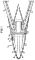
- FIG. 1 shows a fuselage tip 10 of a combat aircraft, the outside of it via a Teflon bushing 11 with the fuselage 12 of the fighter plane is connected.
- the fuselage tip 10 is largely formed as a hollow body which is delimited by a wall 13.
- a measuring device for detection of back pressure and static pressures.
- the measuring device consists essentially from a magazine 20 for pressure sensors, an electrical Evaluation unit 40 and a plurality of air inlet openings 30, which are provided in the wall 13 of the fuselage tip 10.
- the Air inlet openings 30 are connected via connecting channels 31 to the the circular disk-shaped magazine 20 arranged pressure sensors 21 (see Figure 3) connected.
- the connecting channels 31 in Figure 1 only by dashed lines Lines shown.
- FIG. 1 shows a heating device 50 with a heating element 51, the front of the magazine 20 for the pressure sensors on the inside the wall 13 of the fuselage tip 10 is arranged.
- the heating element 51 is in direct contact with the wall 13 of the fuselage tip 10.
- the heating device 50 is intended in particular to freeze the Prevent air inlet openings 30 and the connecting channels 31.
- FIG. 1 there are lightning discharge tubes 14 in the fuselage 12 of the combat aircraft arranged. These lightning rod 14 have the task Lightning striking the fuselage tip 10 to be derived directly.
- lightning currents generated by lightning which in the fuselage tip 10th hammer in, first derived over the surface of the fuselage tip. In the transition from the fuselage tip 10 to the fuselage of the aircraft these lightning currents are then transmitted to the lightning discharge tubes 14. On in this way it is avoided that those hitting the fuselage tip 10 Flash the measuring device and other instruments, not shown inside the tip of the fuselage.
- Figures 3 and 4 each show a plan view of a circular disc Magazine 20 for receiving pressure sensors 21 and an electrical evaluation unit 40 in the form of a circular disk.
- FIG. 3 As can be seen in particular from Figure 3, are on the circular disc Magazine 20 arranged a total of eleven pressure sensors 21.
- the number of pressure sensors is again purely exemplary.
- Within of the circular disk-shaped magazine 20 are through holes 28 provided through which heating lines 52, 53 are passed. These heating lines 52, 53 are part of the heating device 50 and lead to the heating element 51 ( Figure 1). Passing the Heating elements 52, 53 through the through holes 28 of the circular disc Magazine 20 has the advantage that the entire cross section the fuselage tip 10 for receiving the circular disc Magazine 20 can be used. In this way, the for the inclusion of the pressure sensors 21 available space can be optimally used within the fuselage tip 10.
- the electrical evaluation unit 40 contains all components that are necessary to the signals generated in the pressure sensors 21 with regard to the measured back pressure and static pressure, that all necessary air data parameters are calculated from them can. To the group of those necessary for this, but in the present one Description of components not described in detail also belong Microprocessors or such signal converters that carry electrical signals in can convert optical signals.
- the electrical evaluation unit 40 and the magazine 20 for the pressure sensors 21 directly assigned.
- a compact unit is formed in the the recorded print data processed immediately and into optical signals can be transformed. It preferably forms from the evaluation unit 40 the magazine 20 existing unit the conclusion the fuselage tip 10. On the one hand, this takes up the space required reduced for the measuring device. Secondly, it prevents possibly outgoing electrical signals in interaction with others Instruments and can influence them.
- FIG. 5 shows the basic structure of a pressure sensor 21.
- the pressure sensor 21 consists of a base body 22 in which one C R electrode and one C P electrode 23 24 are arranged.
- the base body 22 is connected via a spacer 25 to a membrane 26, which in turn has a counter electrode 27.
- the base body 22, the spacer 25 and the membrane 27 are made of a ceramic material.
- the spacer 25 Due to the spatial separation of the respective electrodes by the spacer 25 corresponds to the pressure sensor 21 in the construction of a capacitor.
- the membrane 26 By moving the membrane 26 in the direction of the base body 22 and thus the counter electrode 27 in the direction of the electrodes 23, 24 the capacitance defined by the electrode surfaces is changed. Since the displacement of the membrane 26 is dependent on that in the Connection channel 31 standing air pressure, is the change in capacity between electrodes 23, 24 and 27 proportional to the change of air pressure.
- the pressure sensor 21 is suitable, each convert the prevailing air pressure into an electrical signal.
- the electrical generated in this way in the pressure sensors 21 Signals are forwarded to the electrical evaluation unit 40 which has a redundant structure.
- This electrical evaluation unit 40 is close behind the circular disk-shaped magazine 20 for the Pressure sensors 21 arranged and contains all electrical components, those for the evaluation and forwarding of these electrical signals are necessary.
- the electrical Evaluation unit 40 a microprocessor in which by real time related algorithm calculation all required air data parameters can be derived from the measured dynamic and static pressure. These relevant air data parameters are in particular altitude, speed, Mach number, angle of attack and sliding angle.
- the microprocessor Calculated values are not considered digital signals shown signal converter supplied. Be in this signal converter the microprocessor's electrical output signals into optical signals transformed. These resulting optical signals can be on simple way via a light pipe for further processing and Usage forwarded to the flight control computer of the combat aircraft will.
- the invention Measuring device equipped with a heating device 50.
- the Heating device 50 consists of a heating element 51, which in the present Embodiment is operated electrically.
- the electrical Heating element 51 is connected to a suitable one via heating lines 52, 53 Power source (not shown) connected.
- the heating element 51 is on the inside of the wall 13 from the fuselage tip 10.
- the fuselage tip is made of a heat-conducting Material is produced, is activated when the heating element 51st the heat generated therein on the fuselage tip 10 and thus also on the air inlet holes 30 transmitted.
- the heater thus prevents it on the fuselage tip 10 or in the air inlet holes 30 can lead to icing.
- both the magazine 20 for the Pressure sensors 21 as well as the electrical evaluation unit 40 in that area of the fuselage tip 10 which is the largest Has diameter. This is in the present embodiment the end of the trunk tip. This enables that as many as possible - in the present case eleven - pressure sensors 21 can be accommodated in magazine 20. This will increase accuracy and increased reliability of the measuring device according to the invention.
- the pressure sensors 21 is located inside of the magazine 20 or the electrical evaluation unit 40 through holes 28, 41.
- the through holes 28 of the magazine 20 is arranged in such an area in which pressure sensors 21 cannot be included. Since the through holes 28, 41 serve to accommodate the heating lines 52, 53, which are used for the supply of the heating element 51 with electrical current are necessary the arrangement of the heating lines 52, 53 described for the Available space within the fuselage tip 10 is used optimally.
Landscapes
- Engineering & Computer Science (AREA)
- Aviation & Aerospace Engineering (AREA)
- Physics & Mathematics (AREA)
- General Physics & Mathematics (AREA)
- Measuring Fluid Pressure (AREA)
Applications Claiming Priority (2)
| Application Number | Priority Date | Filing Date | Title |
|---|---|---|---|
| DE19640606 | 1996-10-01 | ||
| DE19640606A DE19640606C1 (de) | 1996-10-01 | 1996-10-01 | Meßeinrichtung zur Erfassung von Stau- und Statikdrücken bei einem Fluggerät |
Publications (3)
| Publication Number | Publication Date |
|---|---|
| EP0834743A2 true EP0834743A2 (fr) | 1998-04-08 |
| EP0834743A3 EP0834743A3 (fr) | 1998-11-11 |
| EP0834743B1 EP0834743B1 (fr) | 2002-04-17 |
Family
ID=7807646
Family Applications (1)
| Application Number | Title | Priority Date | Filing Date |
|---|---|---|---|
| EP97115836A Expired - Lifetime EP0834743B1 (fr) | 1996-10-01 | 1997-09-11 | Dispositif de mesure pour détecter les pressions dynamiques et statiques d'un aéronef |
Country Status (4)
| Country | Link |
|---|---|
| US (1) | US6038932A (fr) |
| EP (1) | EP0834743B1 (fr) |
| DE (2) | DE19640606C1 (fr) |
| RU (1) | RU2139545C1 (fr) |
Cited By (4)
| Publication number | Priority date | Publication date | Assignee | Title |
|---|---|---|---|---|
| RU2165603C1 (ru) * | 2000-02-15 | 2001-04-20 | Открытое акционерное общество Пермская научно-производственная приборостроительная компания | Приемник давлений |
| RU2171456C1 (ru) * | 2000-02-15 | 2001-07-27 | Открытое акционерное общество Пермская научно-производственная приборостроительная компания | Приемник давлений |
| RU2187821C1 (ru) * | 2001-01-29 | 2002-08-20 | Открытое акционерное общество "Казанское научно-производственное предприятие "Вертолеты-МИ" | Устройство для измерения скоростного напора на лопасти несущего винта вертолета |
| RU2245525C2 (ru) * | 2002-05-06 | 2005-01-27 | Открытое акционерное Общество "Аэроприбор-Восход" (ОАО "Аэроприбор-Восход") | Приемник воздушных давлений |
Families Citing this family (28)
| Publication number | Priority date | Publication date | Assignee | Title |
|---|---|---|---|---|
| RU2135971C1 (ru) * | 1998-07-06 | 1999-08-27 | Центральный аэрогидродинамический институт им.проф.Н.Е.Жуковского | Приемник воздушного давления |
| FR2784457B1 (fr) * | 1998-10-13 | 2001-01-05 | Sextant Avionique | Instruments combines de secours pour aeronef |
| FR2793022B1 (fr) * | 1999-04-30 | 2001-07-13 | Sextant Avionique | Sonde multifonctions fixe pour aeronef |
| US6205376B1 (en) * | 1999-06-22 | 2001-03-20 | Rockwell Collins, Inc. | Blocked pitot-static monitor |
| DE10001813C2 (de) * | 2000-01-18 | 2003-10-30 | Eads Deutschland Gmbh | Meßsystem zur Ermittlung von Luftdaten eines Luftfahrzeuges sowie ein Verfahren zur Bestimmung der Luftdaten |
| US6439048B1 (en) | 2000-09-28 | 2002-08-27 | National Research Council | In-flight calibration of air data systems using a nose-mask sensor |
| US6609421B2 (en) | 2001-05-08 | 2003-08-26 | Rosemount Aerospace Inc. | Sideslip correction for a multi-function three probe air data system |
| DE10124530B8 (de) * | 2001-05-19 | 2006-01-12 | Eads Deutschland Gmbh | Sensorstruktur zur Strömungsdatenmessung an einem Strömungskörper |
| RU2290646C1 (ru) * | 2005-08-26 | 2006-12-27 | Федеральное государственное унитарное предприятие "Центральный аэрогидродинамический институт им. проф. Н.Е. Жуковского" (ФГУП "ЦАГИ") | Система измерения воздушных параметров полета |
| RU2307357C1 (ru) * | 2005-12-07 | 2007-09-27 | Казанский государственный технический университет им. А.Н. Туполева | Способ измерения воздушных сигналов вертолета и система для его осуществления |
| RU2307358C1 (ru) * | 2005-12-07 | 2007-09-27 | Казанский государственный технический университет им. А.Н. Туполева | Система воздушных сигналов вертолета |
| US7389686B2 (en) * | 2006-03-22 | 2008-06-24 | Honeywell International Inc. | Methods and systems for determining air data parameters |
| US8240331B2 (en) * | 2008-10-16 | 2012-08-14 | Honeywell International Inc. | Negative pressure relief valve assembly |
| KR101089989B1 (ko) * | 2009-12-24 | 2011-12-05 | 한국항공우주연구원 | 공기 데이터 센서장치 |
| US8924184B2 (en) | 2010-01-28 | 2014-12-30 | Analysis And Measurement Services Corporation | Pitot tube diagnostic systems and methods |
| US20110184701A1 (en) * | 2010-01-28 | 2011-07-28 | Analysis And Measurement Services Corporation | Pitot Tube Diagnostic System |
| FR2960596B1 (fr) * | 2010-05-25 | 2014-05-02 | Turbomeca | Dispositif d'acquisition/distribution multipoints de fluide, en particulier sonde de prise de pression dans une entree d'air de turbomachine |
| US8810448B1 (en) * | 2010-11-18 | 2014-08-19 | Raytheon Company | Modular architecture for scalable phased array radars |
| DE102010052905B4 (de) * | 2010-12-01 | 2014-08-28 | Deutsches Zentrum für Luft- und Raumfahrt e.V. | Sensoreneinrichtung zur Messung einer Anströmrichtung und Auswerteeinrichtung dafür |
| US10401376B2 (en) * | 2014-03-28 | 2019-09-03 | Honeywell International Inc. | Co-location of high-maintenance air data system components into one LRU |
| EP2998817B1 (fr) * | 2014-09-16 | 2017-06-07 | Aviovision | Système permettant de calculer les performances de l'aéronef et procédé de réalisation desdits calculs |
| FR3057358A1 (fr) * | 2016-10-10 | 2018-04-13 | Airbus Operations (S.A.S.) | Dispositif de mesure de parametres de vol a capteurs optiques de deformation portes par le radome d'un aeronef |
| US10323997B2 (en) | 2017-07-03 | 2019-06-18 | The Boeing Company | Systems and methods for correcting acoustic error in pressure sensors |
| JP2021524013A (ja) * | 2018-05-22 | 2021-09-09 | インディアン・スペース・リサーチ・オーガニゼイションIndian Space Research Organisation | 近接ポート間の圧力パターンを用いてフラッシュ型エアデータシステムの誤った圧力測定を検出するためのシステム及び方法 |
| CN111846192B (zh) * | 2020-06-04 | 2022-06-17 | 中国人民解放军国防科技大学 | 一种飞行器参数在线辨识飞行验证模拟舱段 |
| EP4124867A1 (fr) * | 2021-07-29 | 2023-02-01 | Rockwell Collins, Inc. | Capteur d'angle d'attaque de pression différentielle |
| US11579163B1 (en) | 2021-07-29 | 2023-02-14 | Rockwell Collins, Inc. | Differential pressure angle of attack sensor |
| US20260050004A1 (en) * | 2024-08-14 | 2026-02-19 | The Boeing Company | Pitot-static instrument to determine airspeed for an aircraft |
Family Cites Families (21)
| Publication number | Priority date | Publication date | Assignee | Title |
|---|---|---|---|---|
| CA464474A (fr) * | 1950-04-18 | Canadian Westinghouse Company | Indicateur de vitesse aerienne par lampe pitot | |
| US3079758A (en) * | 1960-02-23 | 1963-03-05 | Northrop Corp | Flow direction sensor |
| US3262316A (en) * | 1962-08-28 | 1966-07-26 | Douglas Aircraft Co Inc | Static position error compensation system and apparatus |
| DE1297921B (de) * | 1965-03-17 | 1969-06-19 | Smiths Industries Ltd | Pitot-Staudrucksonde |
| GB1092939A (en) * | 1965-06-17 | 1967-11-29 | British Aircraft Corp Ltd | Improvements relating to lightning conductors for aircraft |
| US3318146A (en) * | 1966-02-14 | 1967-05-09 | Rosemount Eng Co Ltd | Pressure sensing instrument for aircraft |
| DE2138495A1 (de) * | 1971-07-31 | 1973-02-01 | Dornier Ag | Heizeinrichtung fuer stroemungssonden |
| GB1579638A (en) * | 1977-06-24 | 1980-11-19 | Secr Defence | Airstream pressure sensing probes |
| US4378696A (en) * | 1981-02-23 | 1983-04-05 | Rosemount Inc. | Pressure sensor for determining airspeed altitude and angle of attack |
| US4458137A (en) * | 1981-04-09 | 1984-07-03 | Rosemount Inc. | Electric heater arrangement for fluid flow stream sensors |
| SU1364994A1 (ru) * | 1985-06-10 | 1988-01-07 | Предприятие П/Я А-3697 | Приемник статического давлени |
| DE3544144A1 (de) * | 1985-12-13 | 1987-06-25 | Eduard Prof Dr Ing Igenbergs | Verfahren und vorrichtung zur ermittlung eines anstroemwinkels an fahrzeugen |
| US4718273A (en) * | 1985-12-31 | 1988-01-12 | The Garrett Corporation | Combination alpha, static and total pressure probe |
| US4836019A (en) * | 1987-08-27 | 1989-06-06 | Rosemount Inc. | Compact air data sensor |
| DE3923753A1 (de) * | 1989-07-18 | 1991-01-31 | Nord Micro Elektronik Feinmech | Sonde und verfahren zum messen der relativgeschwindigkeit eines anstroemenden mediums |
| SU1831116A1 (ru) * | 1989-08-09 | 1995-05-10 | Казанский Авиационный Институт Им.А.Н.Туполева | Устройство для определения скорости и направления потока в плоскости измерения |
| US5025661A (en) * | 1989-12-11 | 1991-06-25 | Allied-Signal Inc. | Combination air data probe |
| DE4207951C2 (de) * | 1992-03-10 | 1995-08-31 | Mannesmann Ag | Kapazitiver Druck- oder Differenzdrucksensor in Glas-Silizium-Technik |
| RU2046344C1 (ru) * | 1992-11-26 | 1995-10-20 | Государственный Сибирский научно-исследовательский институт авиации им. С.А.Чаплыгина | Устройство для измерения воздушной скорости сверхлегких летательных аппаратов |
| GB9300305D0 (en) * | 1993-01-08 | 1993-03-10 | Short Brothers Plc | Aerodynamic pressure sensor systems |
| US5438880A (en) * | 1994-05-17 | 1995-08-08 | United Technologies Corporation | Electrostatic linear airspeed transducer |
-
1996
- 1996-10-01 DE DE19640606A patent/DE19640606C1/de not_active Expired - Fee Related
-
1997
- 1997-09-11 EP EP97115836A patent/EP0834743B1/fr not_active Expired - Lifetime
- 1997-09-11 DE DE59707026T patent/DE59707026D1/de not_active Expired - Lifetime
- 1997-09-30 RU RU97116199A patent/RU2139545C1/ru active
- 1997-10-01 US US08/942,224 patent/US6038932A/en not_active Expired - Lifetime
Non-Patent Citations (1)
| Title |
|---|
| None |
Cited By (4)
| Publication number | Priority date | Publication date | Assignee | Title |
|---|---|---|---|---|
| RU2165603C1 (ru) * | 2000-02-15 | 2001-04-20 | Открытое акционерное общество Пермская научно-производственная приборостроительная компания | Приемник давлений |
| RU2171456C1 (ru) * | 2000-02-15 | 2001-07-27 | Открытое акционерное общество Пермская научно-производственная приборостроительная компания | Приемник давлений |
| RU2187821C1 (ru) * | 2001-01-29 | 2002-08-20 | Открытое акционерное общество "Казанское научно-производственное предприятие "Вертолеты-МИ" | Устройство для измерения скоростного напора на лопасти несущего винта вертолета |
| RU2245525C2 (ru) * | 2002-05-06 | 2005-01-27 | Открытое акционерное Общество "Аэроприбор-Восход" (ОАО "Аэроприбор-Восход") | Приемник воздушных давлений |
Also Published As
| Publication number | Publication date |
|---|---|
| DE19640606C1 (de) | 1997-09-11 |
| EP0834743A3 (fr) | 1998-11-11 |
| EP0834743B1 (fr) | 2002-04-17 |
| US6038932A (en) | 2000-03-21 |
| RU2139545C1 (ru) | 1999-10-10 |
| DE59707026D1 (de) | 2002-05-23 |
Similar Documents
| Publication | Publication Date | Title |
|---|---|---|
| EP0834743B1 (fr) | Dispositif de mesure pour détecter les pressions dynamiques et statiques d'un aéronef | |
| DE2640087C2 (fr) | ||
| DE2527505C3 (de) | Thermischer Strömungsmeßumformer | |
| DE2018663A1 (de) | Verfahren und Vorrichtung zur optischen Temperaturmessung | |
| DE2521974A1 (de) | Fluessigkeits-chromatograph | |
| DE2046192B2 (de) | Vorrichtung zur Messung der Strömungsgeschwindigkeit | |
| DE3713981A1 (de) | Waermeuebergangsmessgeraet, insbesondere stroemungswaechter | |
| DE2310817C3 (de) | Vorrichtung zur Erfassung von in einem Strömungsmittel mitgeführten Partikeln, insbesondere Rauchmelder | |
| DE2651645A1 (de) | Roentgenfluoreszenzspektrometer | |
| DE3410394C2 (de) | Sicherheitsvorrichtung für ein Umlaufsystem und Tintentrahldrucker | |
| EP0380046A2 (fr) | Méthode pour tester des compteurs, en particulier des compteurs d'électricité, de gaz ou d'eau et dispositif pour réaliser cette méthode | |
| DE1698277B2 (de) | Luftgeschwindigkeitsmessvorrichtung | |
| DE3524379C2 (fr) | ||
| DE2109568A1 (de) | Nachweissystem für ein Ultrarot-Gasanalysegerät | |
| DE2210900C3 (de) | Hochtemperaturdruckmeßsonde | |
| DE1773682C3 (de) | Vorrichtung zur Ermittlung eines statischen Strömungsmitteldruckes | |
| DE2604302A1 (de) | Detektorzellenanordnung | |
| DE102017130135A1 (de) | Zustandsüberwachung eines Temperatursensors | |
| EP0339626B1 (fr) | Capteur | |
| DE2234680A1 (de) | Durchflussmesser | |
| DE3133744A1 (de) | Einrichtung zur bestimmung der durchgangscharakteristik eines partikelschwarms | |
| DE3005497C2 (fr) | ||
| DE2749229C2 (de) | Nichtdispersives Infrarot-Gasanalysengerät | |
| DE3509416A1 (de) | Messvorrichtung zur bestimmung des durchflusses eines stroemenden mediums | |
| DE4432940C2 (de) | Infrarot-Gasanalysator |
Legal Events
| Date | Code | Title | Description |
|---|---|---|---|
| PUAI | Public reference made under article 153(3) epc to a published international application that has entered the european phase |
Free format text: ORIGINAL CODE: 0009012 |
|
| AK | Designated contracting states |
Kind code of ref document: A2 Designated state(s): DE FR GB SE |
|
| 17P | Request for examination filed |
Effective date: 19980522 |
|
| PUAL | Search report despatched |
Free format text: ORIGINAL CODE: 0009013 |
|
| AK | Designated contracting states |
Kind code of ref document: A3 Designated state(s): AT BE CH DE DK ES FI FR GB GR IE IT LI LU MC NL PT SE |
|
| AKX | Designation fees paid |
Free format text: DE FR GB SE |
|
| RAP1 | Party data changed (applicant data changed or rights of an application transferred) |
Owner name: DAIMLERCHRYSLER AG Owner name: NORD-MICRO ELEKTRONIK FEINMECHANIK AG |
|
| RAP1 | Party data changed (applicant data changed or rights of an application transferred) |
Owner name: DAIMLERCHRYSLER AG Owner name: NORD-MICRO AG & CO. OHG |
|
| GRAG | Despatch of communication of intention to grant |
Free format text: ORIGINAL CODE: EPIDOS AGRA |
|
| 17Q | First examination report despatched |
Effective date: 20010716 |
|
| GRAG | Despatch of communication of intention to grant |
Free format text: ORIGINAL CODE: EPIDOS AGRA |
|
| GRAH | Despatch of communication of intention to grant a patent |
Free format text: ORIGINAL CODE: EPIDOS IGRA |
|
| GRAH | Despatch of communication of intention to grant a patent |
Free format text: ORIGINAL CODE: EPIDOS IGRA |
|
| REG | Reference to a national code |
Ref country code: GB Ref legal event code: IF02 |
|
| RAP1 | Party data changed (applicant data changed or rights of an application transferred) |
Owner name: EADS DEUTSCHLAND GMBH Owner name: NORD-MICRO AG & CO. OHG |
|
| GRAA | (expected) grant |
Free format text: ORIGINAL CODE: 0009210 |
|
| AK | Designated contracting states |
Kind code of ref document: B1 Designated state(s): DE FR GB SE |
|
| GBT | Gb: translation of ep patent filed (gb section 77(6)(a)/1977) |
Effective date: 20020417 |
|
| REF | Corresponds to: |
Ref document number: 59707026 Country of ref document: DE Date of ref document: 20020523 |
|
| ET | Fr: translation filed | ||
| PLBE | No opposition filed within time limit |
Free format text: ORIGINAL CODE: 0009261 |
|
| STAA | Information on the status of an ep patent application or granted ep patent |
Free format text: STATUS: NO OPPOSITION FILED WITHIN TIME LIMIT |
|
| 26N | No opposition filed |
Effective date: 20030120 |
|
| REG | Reference to a national code |
Ref country code: GB Ref legal event code: 732E |
|
| REG | Reference to a national code |
Ref country code: FR Ref legal event code: TP |
|
| REG | Reference to a national code |
Ref country code: DE Ref legal event code: R082 Ref document number: 59707026 Country of ref document: DE Representative=s name: FLUEGEL PREISSNER KASTEL SCHOBER, DE |
|
| REG | Reference to a national code |
Ref country code: DE Ref legal event code: R082 Ref document number: 59707026 Country of ref document: DE Representative=s name: FLUEGEL PREISSNER SCHOBER SEIDEL PATENTANWAELT, DE Effective date: 20140819 Ref country code: DE Ref legal event code: R082 Ref document number: 59707026 Country of ref document: DE Representative=s name: FLUEGEL PREISSNER KASTEL SCHOBER PATENTANWAELT, DE Effective date: 20140819 Ref country code: DE Ref legal event code: R081 Ref document number: 59707026 Country of ref document: DE Owner name: NORD-MICRO GMBH & CO. OHG, DE Free format text: FORMER OWNERS: NORD-MICRO AG & CO. OHG, 60388 FRANKFURT, DE; EADS DEUTSCHLAND GMBH, 85521 OTTOBRUNN, DE Effective date: 20140819 Ref country code: DE Ref legal event code: R081 Ref document number: 59707026 Country of ref document: DE Owner name: AIRBUS DEFENCE AND SPACE GMBH, DE Free format text: FORMER OWNERS: NORD-MICRO AG & CO. OHG, 60388 FRANKFURT, DE; EADS DEUTSCHLAND GMBH, 85521 OTTOBRUNN, DE Effective date: 20140819 Ref country code: DE Ref legal event code: R081 Ref document number: 59707026 Country of ref document: DE Owner name: NORD-MICRO AG & CO. OHG, DE Free format text: FORMER OWNERS: NORD-MICRO AG & CO. OHG, 60388 FRANKFURT, DE; EADS DEUTSCHLAND GMBH, 85521 OTTOBRUNN, DE Effective date: 20140819 Ref country code: DE Ref legal event code: R081 Ref document number: 59707026 Country of ref document: DE Owner name: NORD-MICRO AG & CO. OHG, DE Free format text: FORMER OWNER: NORD-MICRO AG & CO. OHG, EADS DEUTSCHLAND GMBH, , DE Effective date: 20140819 Ref country code: DE Ref legal event code: R081 Ref document number: 59707026 Country of ref document: DE Owner name: AIRBUS DEFENCE AND SPACE GMBH, DE Free format text: FORMER OWNER: NORD-MICRO AG & CO. OHG, EADS DEUTSCHLAND GMBH, , DE Effective date: 20140819 |
|
| PGFP | Annual fee paid to national office [announced via postgrant information from national office to epo] |
Ref country code: DE Payment date: 20140925 Year of fee payment: 18 |
|
| PGFP | Annual fee paid to national office [announced via postgrant information from national office to epo] |
Ref country code: SE Payment date: 20140918 Year of fee payment: 18 Ref country code: GB Payment date: 20140919 Year of fee payment: 18 Ref country code: FR Payment date: 20140919 Year of fee payment: 18 |
|
| REG | Reference to a national code |
Ref country code: DE Ref legal event code: R082 Ref document number: 59707026 Country of ref document: DE Representative=s name: FLUEGEL PREISSNER SCHOBER SEIDEL PATENTANWAELT, DE Ref country code: DE Ref legal event code: R082 Ref document number: 59707026 Country of ref document: DE Representative=s name: FLUEGEL PREISSNER KASTEL SCHOBER PATENTANWAELT, DE Ref country code: DE Ref legal event code: R081 Ref document number: 59707026 Country of ref document: DE Owner name: NORD-MICRO GMBH & CO. OHG, DE Free format text: FORMER OWNERS: AIRBUS DEFENCE AND SPACE GMBH, 85521 OTTOBRUNN, DE; NORD-MICRO AG & CO. OHG, 60388 FRANKFURT, DE Ref country code: DE Ref legal event code: R081 Ref document number: 59707026 Country of ref document: DE Owner name: AIRBUS DEFENCE AND SPACE GMBH, DE Free format text: FORMER OWNERS: AIRBUS DEFENCE AND SPACE GMBH, 85521 OTTOBRUNN, DE; NORD-MICRO AG & CO. OHG, 60388 FRANKFURT, DE |
|
| REG | Reference to a national code |
Ref country code: DE Ref legal event code: R119 Ref document number: 59707026 Country of ref document: DE |
|
| REG | Reference to a national code |
Ref country code: SE Ref legal event code: EUG |
|
| GBPC | Gb: european patent ceased through non-payment of renewal fee |
Effective date: 20150911 |
|
| PG25 | Lapsed in a contracting state [announced via postgrant information from national office to epo] |
Ref country code: SE Free format text: LAPSE BECAUSE OF NON-PAYMENT OF DUE FEES Effective date: 20150912 |
|
| REG | Reference to a national code |
Ref country code: FR Ref legal event code: ST Effective date: 20160531 |
|
| PG25 | Lapsed in a contracting state [announced via postgrant information from national office to epo] |
Ref country code: DE Free format text: LAPSE BECAUSE OF NON-PAYMENT OF DUE FEES Effective date: 20160401 Ref country code: GB Free format text: LAPSE BECAUSE OF NON-PAYMENT OF DUE FEES Effective date: 20150911 |
|
| PG25 | Lapsed in a contracting state [announced via postgrant information from national office to epo] |
Ref country code: FR Free format text: LAPSE BECAUSE OF NON-PAYMENT OF DUE FEES Effective date: 20150930 |