EP0834755A2 - Optisches Kabel oder optisches Element - Google Patents
Optisches Kabel oder optisches Element Download PDFInfo
- Publication number
- EP0834755A2 EP0834755A2 EP97402145A EP97402145A EP0834755A2 EP 0834755 A2 EP0834755 A2 EP 0834755A2 EP 97402145 A EP97402145 A EP 97402145A EP 97402145 A EP97402145 A EP 97402145A EP 0834755 A2 EP0834755 A2 EP 0834755A2
- Authority
- EP
- European Patent Office
- Prior art keywords
- optical
- cable
- optical cable
- fiber optic
- stacks
- Prior art date
- Legal status (The legal status is an assumption and is not a legal conclusion. Google has not performed a legal analysis and makes no representation as to the accuracy of the status listed.)
- Withdrawn
Links
Images


Classifications
-
- G—PHYSICS
- G02—OPTICS
- G02B—OPTICAL ELEMENTS, SYSTEMS OR APPARATUS
- G02B6/00—Light guides; Structural details of arrangements comprising light guides and other optical elements, e.g. couplings
- G02B6/44—Mechanical structures for providing tensile strength and external protection for fibres, e.g. optical transmission cables
- G02B6/4401—Optical cables
- G02B6/441—Optical cables built up from sub-bundles
- G02B6/4411—Matrix structure
-
- G—PHYSICS
- G02—OPTICS
- G02B—OPTICAL ELEMENTS, SYSTEMS OR APPARATUS
- G02B6/00—Light guides; Structural details of arrangements comprising light guides and other optical elements, e.g. couplings
- G02B6/44—Mechanical structures for providing tensile strength and external protection for fibres, e.g. optical transmission cables
- G02B6/4401—Optical cables
- G02B6/4403—Optical cables with ribbon structure
Definitions
- the invention relates to an optical cable or optical element with several on top of each other having attached optical fiber ribbon Stacks of optical fibers and an outer Cover.
- Optical fiber ribbons have a larger number of Optical fibers on that are flat and parallel to each other run in one plane and between two Adhesive films included or by means of UV light cured material are interconnected. These are becoming increasingly common worldwide Optical fiber ribbon for the production of optical cables or optical elements used.
- the Optical fiber ribbons enable compared to known hollow or loose tubes with single and loose optical fibers running in it an essential higher packing density and due to the defined position of the individual optical fibers to each other the application simpler connection techniques like that Mass splicing technology.
- fiber optic ribbons one above the other Join the fiber optic ribbon stack and to enclose with a tubular protective cover.
- a Such an optical element can serve as a central core used or a plurality of such optical elements be stranded around a central element.
- fiber optic ribbon stack in the straight or coiled in the longitudinal direction Arrange grooves of a core.
- Invention therefore addresses the problem of an optical cable or to form an optical element such that it at a large number of optical fibers has compact outer dimensions.
- the advantages that can be achieved by the invention exist in particular that the arrangement of the Fiber optic ribbon stack on top of each other and / or next to each other in the form of a rectangular matrix particularly high packing density of the optical fibers in reach the optical cable or the optical element leaves and unused cross sections in the optical cable or can be minimized in the optical element.
- a optical cable according to the invention or a The optical element according to the invention therefore also has a large number of it Optical fibers particularly small external dimensions on and can be produced easily and inexpensively.
- the matrix-like arrangement the fiber optic ribbon stack the individual Optical fiber very easily identified and the Assembly times especially when using the known Mass splicing technology with special fiber optic ribbon connectors be kept very short. You can also the sleeves have very small external dimensions.
- the optical cable according to the invention can, for. B. as Use the main or local connection cable.
- the optical element according to the invention is suitable on the basis of its very small external dimensions especially for so-called hybrid cables, where in addition Optical fibers also electrical conductors provided for example for message transmission are.
- optical waveguide ribbon stack common within the outer shell are twisted.
- the fiber optic ribbon stack are displaceable relative to each other. Becomes the optical cable or the optical element is bent, so can the individual fiber optic ribbon stack slide along each other and so against each other move. In this way, impermissibly high Strain or compression stresses on the Optical fiber when bending the optical cable or of the optical element avoided.
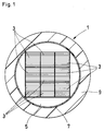
- FIG. 1 shows a first embodiment of the invention an optical cable
- Fig. 2 a Optical fiber ribbon stack
- Fig. 3 shows a second Embodiment according to the invention of an optical Cable as well as Fig. 4 as a third invention Embodiment arranged in a hybrid cable optical element.
- the optical example shown in FIG. 1 Cable 1 has z. B. nine parallel to each other Optical fiber ribbon stack 3, each of which three on top of each other and three side by side in the form of one square matrix are arranged.
- the Optical fiber ribbon stack 3 for example directly to each other and are relative to each other slidable. But it is also possible to switch between the individual fiber optic ribbon stacks 3 thin Arrange foils that stack the optical fiber ribbon 3 cushion each other and the improve relative displaceability to one another.
- the Optical fiber ribbon stack 3 are in this Embodiment to protect the optical fiber twisted together with a large lay length, in one Filling compound 5 embedded and from an outer shell 7 enclosed.
- z. B a jacket 9 from a suitable plastic material provided.
- optical cable 1 has additional layers and that additional in the coat or below the coat Reinforcing elements to protect the optical fibers from arranged inadmissibly high mechanical loads are.
- FIG. 2 shows an example of an optical waveguide ribbon stack 3 of the first shown in FIG. 1 Embodiment, the z. B. ten on top of each other has attached optical fiber ribbon 11, of which, for the sake of simplicity, in FIG three are shown in detail.
- Any of these Optical fiber ribbon 11 has z. B. twelve flat and in parallel next to each other and at equal intervals mutually extending optical waveguide 13, the a ribbon jacket 15 are enclosed.
- the Ribbon jacket 15 of each optical waveguide ribbon 11 z. B. by a common coating of the twelve Optical waveguide 13 with a UV-curable material and then curing this material produced by means of a UV lamp.
- the Fiber optic ribbon 11 of each fiber ribbon stack 3 can for easier production of the optical cable 1 to be connected.
- Cables 1 are, for example, four stacks of optical fibers 3, the z. B. the same structure as the shown in Fig. 2 fiber optic ribbon stack 3 have flat in one plane arranged side by side.
- the fiber optic ribbon stack 3 are shared by an outer shell 7 enclosed, over which a jacket 9 is applied.
- the optical cable 1 after second embodiment of the invention additional Have elements and / or layers.
- the hybrid cable shown by way of example in FIG. 4 21 has a central optical system according to the invention Element 23 with four fiber optic ribbon stacks 3 on.
- the fiber optic ribbon stack 3 correspond for example that shown in FIG. 2 Fiber optic ribbon stack and have ten each superimposed fiber optic ribbon.
- Each two of the optical fiber ribbon stack 3 are one above the other and two next to each other and doing it parallel to each other in the form of a square matrix arranged, the optical waveguide ribbon stack 3 for example, they are in direct contact with one another.
- the Optical fiber ribbon stack 3 are together with long lay length twisted into a filling compound 5 embedded and from a tubular outer shell 7 enclosed.
- Element 23 is, for example, eight electrical wires 25 stranded.
- Each of these electrical wires 25, of which in 4 only one is shown in detail e.g. B. six stranded around a central core 27 with an electrical insulation 29 provided electrical Head 31 on. This is shown in the Embodiment provided a jacket 33. Below of the jacket 33 can optionally additional Layers as well as 33 reinforcement elements in the jacket be provided.
Landscapes
- Physics & Mathematics (AREA)
- General Physics & Mathematics (AREA)
- Optics & Photonics (AREA)
- Optical Couplings Of Light Guides (AREA)
- Light Guides In General And Applications Therefor (AREA)
- Communication Cables (AREA)
- Optical Fibers, Optical Fiber Cores, And Optical Fiber Bundles (AREA)
Abstract
Description
Claims (4)
- Optisches Kabel oder optisches Element mit jeweils mehrere übereinander aneinandergefügte Lichtwellenleiter-Bändchen aufweisenden Lichtwellenleiter-Bändchenstapeln und einer äußeren Hülle, dadurch gekennzeichnet, daß die Lichtwellenleiter-Bändchenstapel (3) übereinander und/oder nebeneinander und dabei parallel zueinander angeordnet sind.
- Optisches Kabel oder optisches Element nach Anspruch 1, dadurch gekennzeichnet, daß die Lichtwellenleiter-Bändchenstapel (3) innerhalb der äußeren Hülle (7) gemeinsam tordiert sind.
- Optisches Kabel oder optisches Element nach Anspruch 1 oder 2, dadurch gekennzeichnet, daß die Lichtwellenleiter-Bändchenstapel (3) relativ zueinander verschiebbar sind.
- Optisches Kabel oder optisches Element nach einem der Ansprüche 1 bis 3, dadurch gekennzeichnet, daß die Lichtwellenleiter-Bändchenstapel (3) flach nebeneinander angeordnet sind.
Applications Claiming Priority (2)
| Application Number | Priority Date | Filing Date | Title |
|---|---|---|---|
| DE19640935A DE19640935A1 (de) | 1996-10-04 | 1996-10-04 | Optisches Kabel oder optisches Element |
| DE19640935 | 1996-10-04 |
Publications (2)
| Publication Number | Publication Date |
|---|---|
| EP0834755A2 true EP0834755A2 (de) | 1998-04-08 |
| EP0834755A3 EP0834755A3 (de) | 1999-02-24 |
Family
ID=7807853
Family Applications (1)
| Application Number | Title | Priority Date | Filing Date |
|---|---|---|---|
| EP97402145A Withdrawn EP0834755A3 (de) | 1996-10-04 | 1997-09-15 | Optisches Kabel oder optisches Element |
Country Status (3)
| Country | Link |
|---|---|
| US (1) | US5878180A (de) |
| EP (1) | EP0834755A3 (de) |
| DE (1) | DE19640935A1 (de) |
Families Citing this family (23)
| Publication number | Priority date | Publication date | Assignee | Title |
|---|---|---|---|---|
| US6192178B1 (en) | 1999-03-31 | 2001-02-20 | Siecor Operations, Llc | Fiber optic cable with profiled group of optical fibers |
| US6621966B2 (en) | 1999-03-31 | 2003-09-16 | Corning Cable Systems Llc | Fiber optic cable with profiled group of optical fibers |
| US6438301B1 (en) | 1999-07-07 | 2002-08-20 | Trw Inc. | Low-torque electro-optical laminated cable and cablewrap |
| US6215932B1 (en) * | 1999-09-15 | 2001-04-10 | Lucent Technologies Inc. | Stacks of optical fiber ribbons closely bound by respective buffer encasements with relatively hard exteriors and relatively soft interiors, associated methods, and associated fiber optic cables |
| US6317542B1 (en) * | 1999-09-15 | 2001-11-13 | Lucent Technologies, Inc. | Fiber optic cables with multiple stacks of optical fiber ribbons |
| US6321013B1 (en) * | 1999-09-15 | 2001-11-20 | Lucent Technologies, Inc. | Stacks of optical fiber ribbons closely bound by respective buffer encasements, associated methods, and associated fiber optic cables |
| US6404962B1 (en) * | 1999-09-15 | 2002-06-11 | Fitel Usa Corp. | Groups of optical fibers closely bound by easily removable buffer encasements, and associated fiber optic cables |
| US6487348B1 (en) * | 1999-11-12 | 2002-11-26 | Fitel Usa Corp. | Variable fiber count optical fiber cable core |
| US6434307B1 (en) * | 2000-08-15 | 2002-08-13 | Alcoa Fujikura Ltd. | Low profile optical fiber ribbon cable |
| US6519399B2 (en) | 2001-02-19 | 2003-02-11 | Corning Cable Systems Llc | Fiber optic cable with profiled group of optical fibers |
| US6744955B2 (en) | 2001-06-29 | 2004-06-01 | Alcatel | Buffer tube having a high fiber count ribbon stack packaging configuration and corner cushions |
| US6778745B2 (en) * | 2001-08-23 | 2004-08-17 | Fitel Usa Corp. | Optical fiber cable apparatus having encased ribbon stack |
| DE10154949A1 (de) * | 2001-11-08 | 2003-05-22 | Ccs Technology Inc | Lichtwellenleiterkabel |
| US6714713B2 (en) | 2002-03-15 | 2004-03-30 | Corning Cable Systems Llc | Optical fiber having a low-shrink buffer layer and methods of manufacturing the same |
| US6909829B2 (en) | 2002-03-28 | 2005-06-21 | Corning Cable Systems Llc | Buffered optical fiber ribbon |
| US20040081413A1 (en) * | 2002-10-28 | 2004-04-29 | Bocanegra Luis M. | High fiber density hybrid cable |
| KR100474726B1 (ko) * | 2002-11-07 | 2005-03-11 | 삼성전자주식회사 | 가입자망 광섬유 케이블 |
| GB2395262A (en) * | 2002-11-11 | 2004-05-19 | Qinetiq Ltd | Optical proximity sensor with array of spot lights and a mask |
| US20040120666A1 (en) * | 2002-12-20 | 2004-06-24 | Chalk Julie A. | Optical fiber ribbon having a semi-solid film on the outer surface thereof |
| US8041168B2 (en) * | 2007-11-09 | 2011-10-18 | Draka Comteq, B.V. | Reduced-diameter ribbon cables with high-performance optical fiber |
| ES2710504T3 (es) * | 2009-12-23 | 2019-04-25 | Prysmian Spa | Cable óptico de microhaces |
| CA3118580A1 (en) * | 2018-11-02 | 2020-05-07 | Corning Research & Development Corporation | Flexible, non-preferential bend jackets for optical fiber cables |
| US11579387B2 (en) * | 2019-08-14 | 2023-02-14 | Sterlite Technologies Limited | Arrangement of optical fibre ribbon stack and an optical fibre ribbon thereof |
Family Cites Families (12)
| Publication number | Priority date | Publication date | Assignee | Title |
|---|---|---|---|---|
| DE4040715A1 (de) * | 1990-12-19 | 1992-06-25 | Siemens Ag | Optisches kabel mit einer vielzahl von lichtwellenleitern |
| US5067830A (en) * | 1990-12-21 | 1991-11-26 | Siecor Corporation | Indented tube for optical ribbon |
| DE4101082C1 (de) * | 1991-01-16 | 1992-05-27 | Kromberg & Schubert, 5600 Wuppertal, De | |
| US5249249A (en) * | 1991-08-27 | 1993-09-28 | Siecor Corporation | Cable utilizing multiple light waveguide stacks |
| DE4211488A1 (de) * | 1992-04-06 | 1993-10-07 | Siemens Ag | Optisches Kabel mit Bandleitungen |
| US5331796A (en) * | 1992-09-16 | 1994-07-26 | Ceeco Machinery Manufacturing Limited | Method and apparatus for applying stacked optical fiber ribbons about a cylindrical core of a fiber optic cable |
| US5487261A (en) * | 1992-09-16 | 1996-01-30 | Ceeco Machinery Manufacturing Ltd. | Method and apparatus for applying flat ribbons about a cylindrical core |
| US5561730A (en) * | 1995-02-23 | 1996-10-01 | Siecor Corporation | Cable containing fiber ribbons with optimized frictional properties |
| US5621841A (en) * | 1995-09-20 | 1997-04-15 | Siecor Corporation | Optical fiber cable containing ribbons in stranded tubes |
| FR2744809B1 (fr) * | 1996-02-13 | 1998-03-13 | Alcatel Cable | Cable a fibres optiques sans elements de renfort |
| US5651082A (en) * | 1996-06-17 | 1997-07-22 | Siecor Corporation | Optical ribbon cables and stranding method |
| US5643393A (en) * | 1996-07-25 | 1997-07-01 | Siecor Corporation | Method for accessing optical ribbon fibers in midspan |
-
1996
- 1996-10-04 DE DE19640935A patent/DE19640935A1/de not_active Withdrawn
-
1997
- 1997-09-15 EP EP97402145A patent/EP0834755A3/de not_active Withdrawn
- 1997-09-24 US US08/936,332 patent/US5878180A/en not_active Expired - Lifetime
Also Published As
| Publication number | Publication date |
|---|---|
| EP0834755A3 (de) | 1999-02-24 |
| DE19640935A1 (de) | 1998-04-09 |
| US5878180A (en) | 1999-03-02 |
Similar Documents
| Publication | Publication Date | Title |
|---|---|---|
| DE19640935A1 (de) | Optisches Kabel oder optisches Element | |
| DE3015732C2 (de) | Freileitungsseil mit in seinem Inneren angeordneten Lichtleitfasern | |
| DE69527112T2 (de) | Wasserblockierendes ungefülltes Einzelrohrkabel | |
| DE3811126A1 (de) | Optisches kabel mit mehreren buendelelementen | |
| DE4335819A1 (de) | Glasfaserkabel | |
| EP0135224B1 (de) | Verfahren zur Herstellung von Kabeln sowie nach diesem Verfahren hergestellte Kabel, insbesondere optische Kabel | |
| EP0840331A1 (de) | Flexible Leitung | |
| DE2801231C2 (de) | Mit Isoliermaterial ummanteltes Starkstromkabel | |
| DE3526823A1 (de) | Element mit mehreren lichtwellenleitern | |
| DE2512830C3 (de) | Fernsehkamerakabel mit Lichtleitfasern | |
| DE2930643A1 (de) | Huelle fuer optische fasern | |
| EP1018662B1 (de) | Optisches Kabel | |
| EP0846970A1 (de) | Verfahren und Vorrichtung zum Herstellen eines optischen Aderbündels oder optischen Kabels | |
| DE29520915U1 (de) | Nachrichtenkabel | |
| DE4416545A1 (de) | Kabel mit elektrischen und optischen Leitern | |
| DE2709106A1 (de) | Optisches kabel | |
| DE19838351C2 (de) | Optisches Kabel und Kabelanordnung | |
| DE3637205A1 (de) | Optisches kabel mit in wechselnder schlagrichtung auf ein mittenelement aufgebrachten verseilelementen | |
| DE29518024U1 (de) | Nachrichtenkabel | |
| EP1575063B1 (de) | Mehradriges Übertragungskabel, insbesondere Datenübertragungskabel | |
| EP0602447B1 (de) | Optisches Kabel | |
| EP0331882A2 (de) | Längswasserdichtes optisches Nachrichtenkabel | |
| DE3446766A1 (de) | Leitungsseil fuer hochspannungsfreileitungen | |
| DE4211489A1 (de) | Optisches Übertragungselement | |
| EP0666576B1 (de) | Energiekabel |
Legal Events
| Date | Code | Title | Description |
|---|---|---|---|
| PUAI | Public reference made under article 153(3) epc to a published international application that has entered the european phase |
Free format text: ORIGINAL CODE: 0009012 |
|
| AK | Designated contracting states |
Kind code of ref document: A2 Designated state(s): DE FR GB IT SE |
|
| PUAL | Search report despatched |
Free format text: ORIGINAL CODE: 0009013 |
|
| RAP1 | Party data changed (applicant data changed or rights of an application transferred) |
Owner name: ALCATEL |
|
| AK | Designated contracting states |
Kind code of ref document: A3 Designated state(s): AT BE CH DE DK ES FI FR GB GR IE IT LI LU MC NL PT SE |
|
| 17P | Request for examination filed |
Effective date: 19990204 |
|
| AKX | Designation fees paid |
Free format text: DE FR GB IT SE |
|
| RAP1 | Party data changed (applicant data changed or rights of an application transferred) |
Owner name: DRAKA COMTEQ B.V. |
|
| RAP1 | Party data changed (applicant data changed or rights of an application transferred) |
Owner name: DRAKA COMTEQ B.V. |
|
| RAP1 | Party data changed (applicant data changed or rights of an application transferred) |
Owner name: DRAKA COMTEQ B.V. |
|
| 17Q | First examination report despatched |
Effective date: 20070717 |
|
| STAA | Information on the status of an ep patent application or granted ep patent |
Free format text: STATUS: THE APPLICATION IS DEEMED TO BE WITHDRAWN |
|
| 18D | Application deemed to be withdrawn |
Effective date: 20071128 |