EP0834891A2 - Im Autoklaven behandelbares Fernbedienungshandgerät - Google Patents
Im Autoklaven behandelbares Fernbedienungshandgerät Download PDFInfo
- Publication number
- EP0834891A2 EP0834891A2 EP97203029A EP97203029A EP0834891A2 EP 0834891 A2 EP0834891 A2 EP 0834891A2 EP 97203029 A EP97203029 A EP 97203029A EP 97203029 A EP97203029 A EP 97203029A EP 0834891 A2 EP0834891 A2 EP 0834891A2
- Authority
- EP
- European Patent Office
- Prior art keywords
- switch means
- switch
- remote control
- activating
- housing
- Prior art date
- Legal status (The legal status is an assumption and is not a legal conclusion. Google has not performed a legal analysis and makes no representation as to the accuracy of the status listed.)
- Withdrawn
Links
- 230000003213 activating effect Effects 0.000 claims abstract description 21
- 238000000034 method Methods 0.000 claims abstract description 16
- 230000005355 Hall effect Effects 0.000 claims abstract description 8
- 239000000463 material Substances 0.000 claims abstract description 3
- 230000004913 activation Effects 0.000 claims description 10
- 230000000994 depressogenic effect Effects 0.000 abstract 1
- 229920001296 polysiloxane Polymers 0.000 description 9
- 238000004140 cleaning Methods 0.000 description 3
- 230000003287 optical effect Effects 0.000 description 3
- 230000001954 sterilising effect Effects 0.000 description 3
- 238000004659 sterilization and disinfection Methods 0.000 description 3
- 235000014676 Phragmites communis Nutrition 0.000 description 2
- 239000012190 activator Substances 0.000 description 2
- 230000002262 irrigation Effects 0.000 description 2
- 238000003973 irrigation Methods 0.000 description 2
- 229920003023 plastic Polymers 0.000 description 2
- 238000001356 surgical procedure Methods 0.000 description 2
- 244000302697 Phragmites karka Species 0.000 description 1
- XAGFODPZIPBFFR-UHFFFAOYSA-N aluminium Chemical compound [Al] XAGFODPZIPBFFR-UHFFFAOYSA-N 0.000 description 1
- 229910052782 aluminium Inorganic materials 0.000 description 1
- 238000003491 array Methods 0.000 description 1
- 230000008602 contraction Effects 0.000 description 1
- 238000001816 cooling Methods 0.000 description 1
- 239000000645 desinfectant Substances 0.000 description 1
- 230000006866 deterioration Effects 0.000 description 1
- 239000013536 elastomeric material Substances 0.000 description 1
- 238000010438 heat treatment Methods 0.000 description 1
- 239000007788 liquid Substances 0.000 description 1
- 238000004519 manufacturing process Methods 0.000 description 1
- 230000007246 mechanism Effects 0.000 description 1
- 230000004048 modification Effects 0.000 description 1
- 238000012986 modification Methods 0.000 description 1
- 239000012778 molding material Substances 0.000 description 1
- 238000000465 moulding Methods 0.000 description 1
- 230000035699 permeability Effects 0.000 description 1
- 239000012466 permeate Substances 0.000 description 1
- 230000002028 premature Effects 0.000 description 1
- 230000008569 process Effects 0.000 description 1
- 238000007789 sealing Methods 0.000 description 1
- 238000000926 separation method Methods 0.000 description 1
Images

Classifications
-
- H—ELECTRICITY
- H01—ELECTRIC ELEMENTS
- H01H—ELECTRIC SWITCHES; RELAYS; SELECTORS; EMERGENCY PROTECTIVE DEVICES
- H01H9/00—Details of switching devices, not covered by groups H01H1/00 - H01H7/00
- H01H9/02—Bases, casings, or covers
- H01H9/0214—Hand-held casings
-
- A—HUMAN NECESSITIES
- A61—MEDICAL OR VETERINARY SCIENCE; HYGIENE
- A61B—DIAGNOSIS; SURGERY; IDENTIFICATION
- A61B17/00—Surgical instruments, devices or methods
- A61B2017/00017—Electrical control of surgical instruments
- A61B2017/00212—Electrical control of surgical instruments using remote controls
-
- H—ELECTRICITY
- H01—ELECTRIC ELEMENTS
- H01H—ELECTRIC SWITCHES; RELAYS; SELECTORS; EMERGENCY PROTECTIVE DEVICES
- H01H2201/00—Contacts
- H01H2201/02—Piezo element
-
- H—ELECTRICITY
- H01—ELECTRIC ELEMENTS
- H01H—ELECTRIC SWITCHES; RELAYS; SELECTORS; EMERGENCY PROTECTIVE DEVICES
- H01H2239/00—Miscellaneous
- H01H2239/024—Miscellaneous with inductive switch
-
- H—ELECTRICITY
- H01—ELECTRIC ELEMENTS
- H01H—ELECTRIC SWITCHES; RELAYS; SELECTORS; EMERGENCY PROTECTIVE DEVICES
- H01H2300/00—Orthogonal indexing scheme relating to electric switches, relays, selectors or emergency protective devices covered by H01H
- H01H2300/014—Application surgical instrument
-
- H—ELECTRICITY
- H01—ELECTRIC ELEMENTS
- H01H—ELECTRIC SWITCHES; RELAYS; SELECTORS; EMERGENCY PROTECTIVE DEVICES
- H01H36/00—Switches actuated by change of magnetic field or of electric field, e.g. by change of relative position of magnet and switch, by shielding
-
- H—ELECTRICITY
- H01—ELECTRIC ELEMENTS
- H01H—ELECTRIC SWITCHES; RELAYS; SELECTORS; EMERGENCY PROTECTIVE DEVICES
- H01H9/00—Details of switching devices, not covered by groups H01H1/00 - H01H7/00
- H01H9/02—Bases, casings, or covers
- H01H9/04—Dustproof, splashproof, drip-proof, waterproof, or flameproof casings
Definitions
- the invention relates to surgical control devices. More particularly, the invention relates to surgical control devices which are operatively connected to a main control unit and remotely situated within the surgical arena at some distance from the main control unit.
- Remote hand controls have become a necessary accessory for operation of certain surgical devices which are situated within the operating room and must be controlled from the sterile field.
- An example of such a device is an irrigation pump used during arthroscopic surgical procedures.
- This pump is an electrically controlled console located in a "non-sterile" environment in the operating room while the patient is located in a "sterile” environment in the operating room.
- the pump is connected via tubing to the patient but, because of the distance of the pump from the patient, direct operation or control of the pump console is impractical.
- the pump being away from the sterile environment where the surgical procedure is being performed, requires a remote control for the surgeon to manually control and adjust pump features and settings.
- This control should preferably be a small, lightweight remote hand control unit and should not only be able to withstand exposure to disinfectants but should also be autoclavable for sterilization purposes after each use.
- the autoclavability requirement means the device should be capable of withstanding exposure to approximately 275°F (121°C) repeatedly for over 1000 cycles in order to be commercially viable (expecting a minimum of 1600 cycles is not unheard of).
- a remote control handpiece for use with a control means for operating a surgical device comprising a plurality of first switch means arranged in a predetermined pattern and designed for transmitting a predetermined signal to the control means upon activation.
- a selectively activatable second switch means is juxtaposed relative to each of the first switch means.
- the first switch means is a Hall effect sensor and the second switch means is a magnet.
- Movable support means is associated with each of the second switch means and enables selective movement of each of the second switch means relative to the associated first switch means to thereby selectively activate or deactivate the first switch means.
- a housing hermetically encases the first switch means and enables non-contiguous activation of the first switch means by the second switch means.
- the invention also resides in a method of producing activating signals in a remote control handpiece for use with a control means for operating a surgical device comprising the steps of providing a first switch means for controlling, upon activation thereof, an operation in the control means.
- the method further comprises hermetically encasing the first switch means in an autoclavable housing; providing a second switch means for activating the first switch means; and juxtapositioning the second switch means adjacent the first switch means.
- the second switch means is normally biased away from the first switch means but it is resiliently supported so it can be moved closer to the first switch means to activate it.
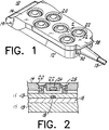
- Figure 1 is a front perspective view of a remote control unit constructed in accordance with the principles of this invention.
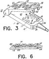
- Figure 2 is a cross-sectional view of Figure 1 taken along the line 2-2.
- Figure 3 is a partially cutaway front perspective view of a remote control unit constructed in accordance with the principles of this invention showing two portions thereof spaced from each other.
- Figure 4 is a front perspective view of an alternate embodiment of a remote control unit showing two portions thereof spaced from each other.
- Figure 5 is a side elevational view of Figure 4.
- Figure 6 is a cross-sectional view of the embodiment of Figure 4 with the two spaced portions of Figure 4 shown juxtaposed together.
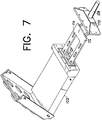
- Figure 7 is an exploded front perspective view of the embodiment of Figure 4.
- an autoclavable remote hand control unit 10 comprises a molded base 12, a cable assembly 13 and a button panel 14.
- the remote hand control 10 makes a plurality of manually operable switches available to a user to remotely control the operation of a main console or surgical device (not shown) to which the other end of the cable may be connected.
- Base 12 encases within a silicone based molding material 15 a circuit in the form of a printed circuit board 16 carrying a plurality of first switch elements such as Hall effect sensors 18 arranged in a predetermined pattern. Each sensor comprises one part of a switch or circuit element which is non-contiguously activatable by another part which is on panel 14.
- non-contiguous refers to the activation of a first element by bringing a second element into the proximity of the first element without the first and second elements touching each other.
- switch means is used herein to encompass other possible arrangements wherein a switch, switch element or other signal transmitting device may be remotely connected to a main console and non-contiguously activated -- e.g. opened or closed -- by some activating stimulus.
- a switch, switch element or other signal transmitting device may be remotely connected to a main console and non-contiguously activated -- e.g. opened or closed -- by some activating stimulus.
- a switch, switch element or other signal transmitting device may be remotely connected to a main console and non-contiguously activated -- e.g. opened or closed -- by some activating stimulus.
- magnetic reed switches shown in Figures 4-7.
- panel 14 is hinged to base 12 by a pair of hinge pins 19 (only one shown) and is provided with a plurality of apertures 20 each of which is adapted to support a flexible, elastomeric (e.g. silicone) button 22 carrying a second switch means such as magnet 24.
- a flexible, elastomeric (e.g. silicone) button 22 carrying a second switch means such as magnet 24.
- magnet 24 is inserted into a recess in the bottom of a respective one of the silicone buttons and is potted or otherwise sealed or secured therein.
- these buttons resemble grommets having an annular groove 28 and are assembled into the apertures 20 in the button panel 14.
- all buttons could be formed as part of a single appropriately shaped silicone sheet received within or attached to panel 14.
- Each button (or, if a single sheet, at least the area around each magnet) is resilient and biased so that with the panel 14 closed (as shown in Figure 1) and without manual pressure the magnet is spaced sufficiently away from the surface of base 12 (as shown in Figure 2) to be unable to activate the associated sensor. All magnets 24 are thus arranged in an array which juxtapositions them over corresponding Hall sensors 18 when panel 14 is in a closed, operational position as shown in Figure 1. Momentary pressure on a selected button will non-contiguously activate the associated Hall sensor by placing the magnet sufficiently close to the sensor.
- Panel 14 may include a pair of closure tabs 30, 32 releasably engageable with a pair of detents 34, 36 to hold the panel closed. Gripping tab 38 facilitates opening and closing the panel.
- buttons 14 While panel 14 is shown hingedly attached to base 12, it may be made totally detachable from the base or it may be made fixedly attached in the form of an open grid or cage for holding the buttons spaced from the surface of the base to facilitate cleaning.
- the resiliency of the buttons provides a positive, tactile feedback to the user so that he or she has some indication that the chosen switch or function has been activated when the button is pushed. Releasing the button allows it to snap back into its normally biased position.
- Other tactile or audible mechanisms may also be devised within the scope of this invention.
- Cable 13 attached to printed circuit board 16 connects the molded base 12 to a control console (for example, an irrigation pump, not shown) by a connector (not shown).
- the cable contains a plurality of signal conducting wires connecting the printed circuit to the main console.
- This cable/printed circuit board assembly is insert molded with silicone in order to produce base 12 without trapping any air inside. Apertures 17 in the printed circuit board enables the liquid silicone to bond the board securely. While silicone is used in the preferred embodiment, one may use any elastomeric material suitable for hermetically sealing printed circuit board 16 and its associated elements.
- Panel 14 is then attached to the cable/printed circuit board assembly thereby aligning the magnets and the Hall sensors for operation.
- the invention is usable without a physical connection to the main console. That is, an infrared or other optical or non-optical device could transmit signals to the console without the need for a cable.
- Remote control 10 is shown in an operational position in Figure 1 where panel 14 lies adjacent the upper surface 40 of base 12. This position enables all magnets 24 to overlie their corresponding Hall sensors 18 as best seen in Figure 2. Simple depression of a selected button 22 moves its magnet 24 closer to its corresponding Hall sensor 18 in order to activate the particular function defined by that sensor.
- the various functions may include power on/off, flow up/down, pressure up/down, etc.
- the remote control 10 may be easily cleaned and autoclaved without doing anything more complicated than simply unlatching closure tabs 30 and 32 by pulling on tab 38.
- Hinged panel 14 is used in the preferred embodiment to enable switch buttons 22 to be separable from the Hall sensors 18. Other such separation means may be suitable as well. This enables switch operation in one position while facilitating cleaning and sterilization in another position. Also, insert molding the printed circuit board assembly and Hall sensors into a silicone base and using Hall sensors eliminates air pockets inside the housing, thus preventing false activation of the switches.
- a remote control unit constructed in accordance with the foregoing description has passed 1,600 autoclave cycles with no deterioration of either button functionality or materials.
- the remote control 100 comprises a base 102 and a hinged panel 104.
- Cable assembly 106 is attached to an adapter plate 110 which is attachable to base 102.
- Printed circuit board 112 is operatively connected to cable 106 and carries a plurality of magnetic switch contacts 114 (e.g. reed switches) arranged in a predetermined pattern which, as shown in Figure 7, may be a simple rectangular array.
- panel 104 has a plurality of apertures each of which retains a flexible elastomeric button 120 intended to activate a corresponding magnetic switch 114.
- base 102 may be an aluminum, plastic or elastomeric casing having a recess 124 to receive the printed circuit board 112. Suitable seal means between cable plate 110 and base 102 may be used to make the assembly hermetically sealed.
- the invention is also embodied in the method of producing an autoclavable remote control.
- the method comprises the steps of providing a hermetically sealed base having a first array of switch elements, each switch element being non-contiguously responsive to an activating stimulus, and providing a second array of activators for producing the activating stimulus.
- the method further comprises juxtaposing the first and second arrays in parallel orientation to enable each of the activators to activate a corresponding one of the switches.
- the method may further comprise the step of hingedly or detachably (fully or partially) attaching the second array to a cover which is movable relative to the base to facilitate the cleaning and sterilization of the remote control.
- Non-contiguously activatable elements other than Hall effect sensors or reed switches may also be used.
- infrared or optical means on the movable panel could be used to trigger a switch means within the sealed base.
- Other mechanical, electrical, piezoelectrical, hydraulic, fluidic, pneumatic, etc. trigger devices may be devised to non-contiguously trigger a switch element hermetically sealed within an impervious housing by using an element situated outside of the housing.
Landscapes
- Surgical Instruments (AREA)
- Instructional Devices (AREA)
- Dental Tools And Instruments Or Auxiliary Dental Instruments (AREA)
- Apparatus For Disinfection Or Sterilisation (AREA)
- Switch Cases, Indication, And Locking (AREA)
Applications Claiming Priority (2)
| Application Number | Priority Date | Filing Date | Title |
|---|---|---|---|
| US2732196P | 1996-10-02 | 1996-10-02 | |
| US27321 | 1996-10-02 |
Publications (2)
| Publication Number | Publication Date |
|---|---|
| EP0834891A2 true EP0834891A2 (de) | 1998-04-08 |
| EP0834891A3 EP0834891A3 (de) | 1998-11-18 |
Family
ID=21837016
Family Applications (1)
| Application Number | Title | Priority Date | Filing Date |
|---|---|---|---|
| EP97203029A Withdrawn EP0834891A3 (de) | 1996-10-02 | 1997-10-01 | Im Autoklaven behandelbares Fernbedienungshandgerät |
Country Status (4)
| Country | Link |
|---|---|
| EP (1) | EP0834891A3 (de) |
| JP (1) | JPH10154431A (de) |
| AU (1) | AU722183B2 (de) |
| CA (1) | CA2216727A1 (de) |
Cited By (11)
| Publication number | Priority date | Publication date | Assignee | Title |
|---|---|---|---|---|
| WO2006047016A1 (en) * | 2004-10-22 | 2006-05-04 | Intergraph Hardware Technologies Company | Tactile feedback plunger switch |
| DE102006051023A1 (de) * | 2006-10-26 | 2008-04-30 | Elobau Elektrobauelemente Gmbh & Co. Kg | Taster |
| WO2013026922A1 (en) * | 2011-08-25 | 2013-02-28 | Endocontrol | Actuating knob for a surgical instrument |
| DE102004041871B4 (de) * | 2004-08-27 | 2014-01-30 | W.O.M. World Of Medicine Ag | Verfahren zur Herstellung einer autoklavierbaren Fernbedienung und autoklavierbare Fernbedienung |
| WO2016077660A1 (en) * | 2014-11-14 | 2016-05-19 | Fisher Controls International Llc | Switch apparatus for enclosures having environmental protection |
| US9433460B2 (en) | 2014-05-30 | 2016-09-06 | Bipad, Llc | Electrosurgery actuator |
| USD778442S1 (en) | 2015-11-19 | 2017-02-07 | Bipad, Llc | Bipolar electrosurgery actuator system |
| EP3386109A1 (de) * | 2017-04-05 | 2018-10-10 | RAFI GmbH & Co. KG | Schaltvorrichtung |
| EP3536270A1 (de) * | 2012-03-22 | 2019-09-11 | Ethicon LLC | Aktivierungsfunktion für ein chirurgisches instrument mit bleistiftgriff |
| DE102018004244A1 (de) * | 2018-05-28 | 2019-11-28 | Karl Storz Se & Co. Kg | Autoklavierbarer Handgriff |
| US10646268B2 (en) | 2016-08-26 | 2020-05-12 | Bipad, Inc. | Ergonomic actuator for electrosurgical tool |
Families Citing this family (3)
| Publication number | Priority date | Publication date | Assignee | Title |
|---|---|---|---|---|
| DE10336731A1 (de) * | 2003-08-11 | 2005-03-17 | Siemens Ag | Funk-Bediensystem und Verfahren zum Betrieb eines Funksystems |
| KR100797673B1 (ko) * | 2006-04-20 | 2008-01-23 | 삼성전기주식회사 | 모듈형 입력장치 및 이를 구비한 휴대용 단말기와원격조정기 |
| JP5466914B2 (ja) * | 2009-10-13 | 2014-04-09 | ホーチキ株式会社 | 防水型機器 |
Family Cites Families (8)
| Publication number | Priority date | Publication date | Assignee | Title |
|---|---|---|---|---|
| DE1690356B2 (de) * | 1967-05-31 | 1972-06-08 | Uninorm Etablissement, Vaduz | Handstueck mit schalt- und bedienungsgeraeten fuer elektrische krankenhauseinrichtungen und verfahren zu seiner herstellung |
| DE7023433U (de) * | 1970-06-23 | 1974-07-11 | Siemens Ag | Handstück für Hochfrequenz-Elektroden |
| US4366463A (en) * | 1981-05-22 | 1982-12-28 | Cooper Industries, Inc. | Keyboard |
| US4705038A (en) * | 1985-01-23 | 1987-11-10 | Dyonics, Inc. | Surgical system for powered instruments |
| US5443065A (en) * | 1991-09-24 | 1995-08-22 | Angeion Corporation | Connector for medical device |
| US5304209A (en) * | 1991-09-24 | 1994-04-19 | Angeion Corporation | Remote-control temporary pacemaker |
| ITRM930784A1 (it) * | 1993-11-25 | 1995-05-25 | Gideon Raphael Tock | Dispositivo di controllo digitale ad induzione magnetica; interuttore e/o variatore di velocita' manuale per il controllo dei manipoli e/o |
| DE19503702B4 (de) * | 1995-02-04 | 2005-10-27 | Nicolay Verwaltungs-Gmbh | Flüssigkeits- und gasdicht gekapselter Schalter, insbesondere für elektrochirurgische Instrumente |
-
1997
- 1997-09-29 CA CA002216727A patent/CA2216727A1/en not_active Abandoned
- 1997-09-30 AU AU39314/97A patent/AU722183B2/en not_active Expired
- 1997-10-01 EP EP97203029A patent/EP0834891A3/de not_active Withdrawn
- 1997-10-02 JP JP9269826A patent/JPH10154431A/ja active Pending
Cited By (18)
| Publication number | Priority date | Publication date | Assignee | Title |
|---|---|---|---|---|
| DE102004041871B4 (de) * | 2004-08-27 | 2014-01-30 | W.O.M. World Of Medicine Ag | Verfahren zur Herstellung einer autoklavierbaren Fernbedienung und autoklavierbare Fernbedienung |
| US7326869B2 (en) | 2004-10-22 | 2008-02-05 | Intergraph Hardware Technologies Company | Tactile feedback plunger switch |
| WO2006047016A1 (en) * | 2004-10-22 | 2006-05-04 | Intergraph Hardware Technologies Company | Tactile feedback plunger switch |
| DE102006051023A1 (de) * | 2006-10-26 | 2008-04-30 | Elobau Elektrobauelemente Gmbh & Co. Kg | Taster |
| US9375206B2 (en) | 2011-08-25 | 2016-06-28 | Endocontrol | Surgical instrument with disengageable handle |
| WO2013026922A1 (en) * | 2011-08-25 | 2013-02-28 | Endocontrol | Actuating knob for a surgical instrument |
| US9700337B2 (en) | 2011-08-25 | 2017-07-11 | Endocontrol | Surgical instrument with disengageable handle |
| EP3536270A1 (de) * | 2012-03-22 | 2019-09-11 | Ethicon LLC | Aktivierungsfunktion für ein chirurgisches instrument mit bleistiftgriff |
| US9433460B2 (en) | 2014-05-30 | 2016-09-06 | Bipad, Llc | Electrosurgery actuator |
| US10456192B2 (en) | 2014-05-30 | 2019-10-29 | Bipad, Llc | Bipolar electrosurgery actuator |
| CN105610058A (zh) * | 2014-11-14 | 2016-05-25 | 费希尔控制产品国际有限公司 | 用于具有环境保护的壳体的开关设备 |
| WO2016077660A1 (en) * | 2014-11-14 | 2016-05-19 | Fisher Controls International Llc | Switch apparatus for enclosures having environmental protection |
| RU2701865C2 (ru) * | 2014-11-14 | 2019-10-02 | Фишер Контролз Интернешнел Ллс | Коммутационное устройство для корпусов, снабженных защитой от внешних воздействий |
| USD778442S1 (en) | 2015-11-19 | 2017-02-07 | Bipad, Llc | Bipolar electrosurgery actuator system |
| US10646268B2 (en) | 2016-08-26 | 2020-05-12 | Bipad, Inc. | Ergonomic actuator for electrosurgical tool |
| EP3386109A1 (de) * | 2017-04-05 | 2018-10-10 | RAFI GmbH & Co. KG | Schaltvorrichtung |
| DE102018004244A1 (de) * | 2018-05-28 | 2019-11-28 | Karl Storz Se & Co. Kg | Autoklavierbarer Handgriff |
| US11141235B2 (en) | 2018-05-28 | 2021-10-12 | Karl Storz Se & Co. Kg | Autoclavable handle |
Also Published As
| Publication number | Publication date |
|---|---|
| CA2216727A1 (en) | 1998-04-02 |
| AU3931497A (en) | 1998-04-09 |
| EP0834891A3 (de) | 1998-11-18 |
| AU722183B2 (en) | 2000-07-27 |
| JPH10154431A (ja) | 1998-06-09 |
Similar Documents
| Publication | Publication Date | Title |
|---|---|---|
| US5959557A (en) | Autoclavable remote hand control | |
| EP0834891A2 (de) | Im Autoklaven behandelbares Fernbedienungshandgerät | |
| US5468240A (en) | Manual control device for laparoscopic instrument | |
| KR101590163B1 (ko) | 수술용 로봇 및 이를 커버하는 멸균 드레이프 | |
| EP0733375B1 (de) | Ventilanordnung für eine chirurgische Kassette | |
| RU2692231C2 (ru) | Хирургическая система со стерильной изоляцией | |
| CN105832277B (zh) | 球囊控制装置用遥控器和内窥镜系统 | |
| US20140100424A1 (en) | Switch cover, switch apparatus and endoscope | |
| US9138216B2 (en) | Portable regulated vacuum pump for medical procedures | |
| US5499969A (en) | Microsurgical cassette | |
| KR101975615B1 (ko) | 수술용 원격제어된 흡입/세척 장치 | |
| US7608039B1 (en) | Hand-held surgical instrument with illuminated keypad | |
| CN103476355A (zh) | 具有锁定功能的关节臂 | |
| EA006224B1 (ru) | Эргономические органы управления в хирургической системе освещения | |
| EP3302216A1 (de) | Endoskop | |
| DK0705198T3 (da) | Fremgangsmåde til fastgørelse af en termoplastisk membran til en pipettes åbning | |
| US10213267B2 (en) | Surgical drape with control mechanism | |
| EP4408255A1 (de) | Endoskop | |
| BR102013006711A2 (pt) | Recurso de ativação para instrumento cirúrgico com pega de lápis | |
| CA3086901C (en) | Handle assembly for a surgical lighting system | |
| US11141235B2 (en) | Autoclavable handle | |
| JP2025004024A (ja) | ロボット制御された外科用器具用のコンパクトな作動構成および拡張可能な器具レシーバ | |
| WO1998011577A1 (en) | Electrical switch | |
| WO1998038903A2 (en) | Hand held control device and associated method | |
| JP2015205178A (ja) | 医療機器を制御するための操作装置 |
Legal Events
| Date | Code | Title | Description |
|---|---|---|---|
| PUAI | Public reference made under article 153(3) epc to a published international application that has entered the european phase |
Free format text: ORIGINAL CODE: 0009012 |
|
| AK | Designated contracting states |
Kind code of ref document: A2 Designated state(s): BE DE ES FR GB IT |
|
| AX | Request for extension of the european patent |
Free format text: AL;LT;LV;RO;SI |
|
| RAP1 | Party data changed (applicant data changed or rights of an application transferred) |
Owner name: LINVATEC CORPORATION |
|
| PUAL | Search report despatched |
Free format text: ORIGINAL CODE: 0009013 |
|
| AK | Designated contracting states |
Kind code of ref document: A3 Designated state(s): AT BE CH DE DK ES FI FR GB GR IE IT LI LU MC NL PT SE |
|
| AX | Request for extension of the european patent |
Free format text: AL;LT;LV;RO;SI |
|
| 17P | Request for examination filed |
Effective date: 19990503 |
|
| AKX | Designation fees paid |
Free format text: BE DE ES FR GB IT |
|
| 17Q | First examination report despatched |
Effective date: 20011010 |
|
| STAA | Information on the status of an ep patent application or granted ep patent |
Free format text: STATUS: THE APPLICATION IS DEEMED TO BE WITHDRAWN |
|
| 18D | Application deemed to be withdrawn |
Effective date: 20020221 |