EP0834935A1 - Batterie mit einer Vorrichtung zur Abführung von Abgasen - Google Patents
Batterie mit einer Vorrichtung zur Abführung von Abgasen Download PDFInfo
- Publication number
- EP0834935A1 EP0834935A1 EP97116726A EP97116726A EP0834935A1 EP 0834935 A1 EP0834935 A1 EP 0834935A1 EP 97116726 A EP97116726 A EP 97116726A EP 97116726 A EP97116726 A EP 97116726A EP 0834935 A1 EP0834935 A1 EP 0834935A1
- Authority
- EP
- European Patent Office
- Prior art keywords
- baffle
- frit
- battery according
- housing
- hood
- Prior art date
- Legal status (The legal status is an assumption and is not a legal conclusion. Google has not performed a legal analysis and makes no representation as to the accuracy of the status listed.)
- Granted
Links
- 239000007789 gas Substances 0.000 title claims abstract description 21
- 239000011324 bead Substances 0.000 claims description 10
- 125000006850 spacer group Chemical group 0.000 claims description 5
- 238000007599 discharging Methods 0.000 claims description 2
- 230000001681 protective effect Effects 0.000 abstract 2
- 239000002253 acid Substances 0.000 description 13
- 238000011161 development Methods 0.000 description 5
- 230000018109 developmental process Effects 0.000 description 5
- 238000004026 adhesive bonding Methods 0.000 description 3
- 238000007872 degassing Methods 0.000 description 3
- 238000005516 engineering process Methods 0.000 description 3
- 239000003792 electrolyte Substances 0.000 description 2
- 239000007788 liquid Substances 0.000 description 2
- 238000012986 modification Methods 0.000 description 2
- 230000004048 modification Effects 0.000 description 2
- 239000002245 particle Substances 0.000 description 2
- 239000000565 sealant Substances 0.000 description 2
- 239000007858 starting material Substances 0.000 description 2
- 241000209035 Ilex Species 0.000 description 1
- 230000002378 acidificating effect Effects 0.000 description 1
- QVGXLLKOCUKJST-UHFFFAOYSA-N atomic oxygen Chemical compound [O] QVGXLLKOCUKJST-UHFFFAOYSA-N 0.000 description 1
- 238000013461 design Methods 0.000 description 1
- 239000002360 explosive Substances 0.000 description 1
- 238000007373 indentation Methods 0.000 description 1
- 238000003780 insertion Methods 0.000 description 1
- 230000037431 insertion Effects 0.000 description 1
- 239000011244 liquid electrolyte Substances 0.000 description 1
- 239000000463 material Substances 0.000 description 1
- 238000000034 method Methods 0.000 description 1
- 239000001301 oxygen Substances 0.000 description 1
- 229910052760 oxygen Inorganic materials 0.000 description 1
- 230000006798 recombination Effects 0.000 description 1
- 238000005215 recombination Methods 0.000 description 1
- 230000001105 regulatory effect Effects 0.000 description 1
- 239000007787 solid Substances 0.000 description 1
- 238000009423 ventilation Methods 0.000 description 1
- 238000003466 welding Methods 0.000 description 1
Images



Classifications
-
- H—ELECTRICITY
- H01—ELECTRIC ELEMENTS
- H01M—PROCESSES OR MEANS, e.g. BATTERIES, FOR THE DIRECT CONVERSION OF CHEMICAL ENERGY INTO ELECTRICAL ENERGY
- H01M50/00—Constructional details or processes of manufacture of the non-active parts of electrochemical cells other than fuel cells, e.g. hybrid cells
- H01M50/30—Arrangements for facilitating escape of gases
- H01M50/308—Detachable arrangements, e.g. detachable vent plugs or plug systems
-
- H—ELECTRICITY
- H01—ELECTRIC ELEMENTS
- H01M—PROCESSES OR MEANS, e.g. BATTERIES, FOR THE DIRECT CONVERSION OF CHEMICAL ENERGY INTO ELECTRICAL ENERGY
- H01M50/00—Constructional details or processes of manufacture of the non-active parts of electrochemical cells other than fuel cells, e.g. hybrid cells
- H01M50/30—Arrangements for facilitating escape of gases
- H01M50/383—Flame arresting or ignition-preventing means
-
- H—ELECTRICITY
- H01—ELECTRIC ELEMENTS
- H01M—PROCESSES OR MEANS, e.g. BATTERIES, FOR THE DIRECT CONVERSION OF CHEMICAL ENERGY INTO ELECTRICAL ENERGY
- H01M50/00—Constructional details or processes of manufacture of the non-active parts of electrochemical cells other than fuel cells, e.g. hybrid cells
- H01M50/30—Arrangements for facilitating escape of gases
- H01M50/394—Gas-pervious parts or elements
-
- H—ELECTRICITY
- H01—ELECTRIC ELEMENTS
- H01M—PROCESSES OR MEANS, e.g. BATTERIES, FOR THE DIRECT CONVERSION OF CHEMICAL ENERGY INTO ELECTRICAL ENERGY
- H01M50/00—Constructional details or processes of manufacture of the non-active parts of electrochemical cells other than fuel cells, e.g. hybrid cells
- H01M50/30—Arrangements for facilitating escape of gases
- H01M50/317—Re-sealable arrangements
- H01M50/325—Re-sealable arrangements comprising deformable valve members, e.g. elastic or flexible valve members
-
- Y—GENERAL TAGGING OF NEW TECHNOLOGICAL DEVELOPMENTS; GENERAL TAGGING OF CROSS-SECTIONAL TECHNOLOGIES SPANNING OVER SEVERAL SECTIONS OF THE IPC; TECHNICAL SUBJECTS COVERED BY FORMER USPC CROSS-REFERENCE ART COLLECTIONS [XRACs] AND DIGESTS
- Y02—TECHNOLOGIES OR APPLICATIONS FOR MITIGATION OR ADAPTATION AGAINST CLIMATE CHANGE
- Y02E—REDUCTION OF GREENHOUSE GAS [GHG] EMISSIONS, RELATED TO ENERGY GENERATION, TRANSMISSION OR DISTRIBUTION
- Y02E60/00—Enabling technologies; Technologies with a potential or indirect contribution to GHG emissions mitigation
- Y02E60/10—Energy storage using batteries
Definitions
- the invention relates to a battery with a battery housing, a hood in which Housing arranged cells and at least one opening for discharging the the gases escaping the cells into which a re-ignition protection frit is inserted, which serves to cause an explosive ignition from the battery case to prevent escaping gases from ignition sparks.
- Such a battery is known from DE-GM 90 15 535. Acting on the battery it is in particular a multi-cell battery, preferably a starter battery.
- the battery as such is from DE-OS 34 44 011 as a so-called Kamina battery known. There is a channel in it to drain the cells escaping, generally acidic gases.
- the re-ignition protection frit known from DE-GM 90 15 535 is in a Edge of the hood of the battery inserted blind hole-like opening sealed and thereby protected from damage. It can also be easily assembled and if necessary be replaced. The side lock locks into the lid reached; disassembly is only possible against resistance.
- the object of the invention is the in a battery of the type mentioned Improve protection of the backfire protection frit.
- this object is achieved in that a baffle is arranged in front of the flashback protection frit.
- the gas flow from the battery initially hits this baffle with the acid drops it may contain. If there are acid drops, they can be separated on the baffle. Of the separate , gas stream freed from the acid drops and particles then reaches the flashback protection frit. He can from there into the open be degassed. This can, as described in DE-GM 90 15 535, be done with or without an elbow and hose. For batteries that work without additional gas discharge (elbow and hose), the outlet connection can be omitted and replaced by a perforated plate with one or more gas openings. The degassing takes place outdoors or in the engine compartment of the motor vehicle in which the battery is located.
- a prechamber is arranged in front of the baffle.
- the antechamber can be used to collect the pre-separated acid.
- the backfire protection frit can be arranged in a filter chamber.
- the pre-chamber and / or the filter chamber can be of a re-ignition protection housing be educated.
- the baffle preferably has one or more openings. The gases arrive through these openings to the backfire protection frit or to the filter chamber.
- the opening or the openings in the upper region of the baffle are provided. If a prechamber is arranged in front of the baffle, this increases the collection space available for the acid.
- Another advantageous development is characterized in that the lower Limits of the openings lie on a horizontal line. If in front of the baffle a prechamber is arranged, this can be used for the acid drops Available collection space can be optimally used.
- the backfire protection frit or the backfire protection housing is preferred fixed in the opening.
- the backfire protection frit or the backfire protection housing So is a side lock provided by one Positional security and security against falling out can be achieved.
- the backfire protection frit or the backfire protection housing is fixed in the opening and can only be pulled out against resistance.
- the fixation can be achieved by the re-ignition protection housing is glued to the hood.
- the fixation can be effected in that the Cover the re-ignition protection frit or the re-ignition protection housing fixing undercut is provided.
- the undercut can be considered as at the The hood provided for the projection to be designed with the indentation of the anti-ignition frit or the re-ignition protection housing to a latch leads.
- the backfire protection frit or the backfire protection housing is then fixed and can only be pulled out against resistance.
- spacers are provided which have a pointed shape and hold the flashback frit in place. These spacers are preferably on the outside of the baffle and / or provided on the inside of an outer part of the re-ignition protection housing. The tips of the spacers form a gas-tight seal. Hereby can bypass the re-ignition protection frit without additional, additional sealants be prevented.
- a cap is placed in front of the baffle, preferably a rubber cap is provided.
- the cap or rubber cap is preferred put on a sleeve.
- the sleeve can be connected to the prechamber part be.
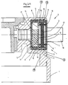
- the hood 1 of a battery which has an opening 2 for Deriving the gases emerging from the cells of the battery.
- a backfire protection frit 3 is used in the opening 2.
- the opening 2 is in the from DE-GM 90 15 535 known way expanded blind hole.
- the flashback protection frit 3 is located in a flashback protection housing 4, which in turn consists of a prechamber part 5, a baffle part 6 and an outer part 7, which is connected to one another, preferably welded, are preferably ultrasonically welded or thermally welded.
- the Pot-shaped prechamber part has an edge 8 which is within the blind hole-like Extension 9 of the opening 2 is provided.
- the inner edge 10 of the Baffle part 6 inserted.
- the outer edge 11 of the baffle part 6 essentially has the same dimensions as the edge 8 of the prechamber part 5 and runs away from it.
- the inner end of the edge 11 is supported at the outer end of the edge 8.
- the edges 10 and 11 are defined by the flat baffle 12 connected to each other.
- the gas stream coming from the battery strikes the baffle plate 12, so that in acid drops contained in the gas stream are separated beforehand.
- the one on this The gas stream, which has been freed from the acid drops, then passes through the in the Baffle plate 12 provided ventilation holes or openings 14 in the filter chamber 15 a, which is formed between the baffle plate 12 and the outer part 7 and in which the anti-ignition frit 3 is located.
- To the ignition protection frit 3 in the Hold in the position shown in the drawing are on the outside of the baffle 12 and the inside of the outer part 7 spacer 16 is provided, which is a tip Have shape. Through this tip profile is under pressure during the welding process of parts 5, 6, 7 takes place a tip seal with the Flashback protection frit 3 formed.
- Fig. 2 From Fig. 2 it can be seen that there are a total of four openings 14, which are located in the upper region of the baffle 12 and whose lower boundaries lie on a horizontal line that the highest possible Acid levels forms.
- the re-ignition protection housing 4 is in the opening 2 of the hood 1 locked. This locking is done by two on the outer Circumferential surface of the outer edge 11 of the baffle part 6 of the re-ignition protection housing 4 provided bead edges 19, which in two corresponding grooves engage on the inner surface of the opening 2 of the hood 1.
- the bead edges 19 and the grooves are in such a way in their height or depth or other configuration matched that the re-ignition protection housing 4 can be reliably installed and can only be dismantled with a tool after assembly.
- the re-ignition protection housing 4 in the opening 2 anchored by a bead fixation, in which the outer edge 11 of the Baffle part 6 with the inner wall of the opening 2 by a counter bead design or groove is anchored and in this way forms a firm connection.
- the Backfire protection housing 4 is with the hood 1 by a bead attachment on the outside with the corresponding counter bead shape or groove in the Hood 19 locked.
- the fixation is achieved by a form-locking bead achieved, i.e. by attaching one or more bead edges on the outside of the re-ignition protection housing, which in corresponding mold groove or snap grooves into the sack-like recess of the cover.
- the re-ignition protection housing 4 can be in the opening 2 also be done by gluing, for example to the in Fig. 3/1 the numbers 19.
- the hood is 1 an undercut 20 fixing the re-ignition protection housing 4 is provided.
- the undercut 20 is a projection that reduces the cross section of the opening 2 designed.
- the backfire protection housing 4 is in the Fig. 3/2 shown position in the locked position.
- the undercut 20 is designed in this way and dimensioned so that it has an insertion of the re-ignition protection housing during assembly 4 allows and then locked, so that a removal of the backfire protection housing 4 is blocked or prevented.
- the axial distance of the undercut 20 from the bottom of the opening 2 is dimensioned such that the Re-ignition protection housing 4 is firmly seated in the axial direction.
- the undercut 20 lies on the outer edge of the outer part 7.
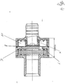
- Figure 4 shows a further modified embodiment, in which the difference to the previously described embodiments with the prechamber part 5 a sleeve X is provided with the longitudinal axis of the re-ignition protection housing 4 runs coaxially and on which a rubber cap Y is attached.
- the Rubber cap Y has a cylindrical jacket part, with which it on the Baffle 12 facing sleeve X is attached, and a bottom part that is parallel runs to the baffle 12.
- the prechamber part 5, the sleeve X and the rubber cap Y are dimensioned such that between the bottom part of the rubber cap Y and Baffle 12 a small distance or gap Z remains. There is also between Sleeve X and the jacket part of the rubber cap Y an interference fit.
- the rubber cap Y works as a valve during operation. Arising when operating the battery Gases and escaping liquid caused by the central degassing in the battery cover escape, are when they hit the rubber cap or on the Bottom part "forced braking". If the pressure continues to rise, the rubber cap Y moved to the baffle 12. If the pressure continues to rise, then the Bottom part of the rubber cap Y on the baffle 12. If the pressure is still there The gases and the liquid continue to rise due to the fit between the sleeve X and the jacket part of the rubber cap Y printed through. You need to by this fit (tension of the rubber cap over the sleeve) and that Material of the rubber cap overcome certain closing pressure and can then in enter the antechamber 17.
- the bottom part of the rubber cap Y thus acts as a baffle. He will first fixed by the interference fit between sleeve X and rubber cap Y and increasing pressure held by the baffle 12.
Landscapes
- Chemical & Material Sciences (AREA)
- Chemical Kinetics & Catalysis (AREA)
- Electrochemistry (AREA)
- General Chemical & Material Sciences (AREA)
- Gas Exhaust Devices For Batteries (AREA)
Abstract
Description


- Fig. 1
- einen Teil einer Starterbatterie in einem Längsschnitt,
- Fig. 2
- einen Schnitt längs der Linie II-II in Fig. 1,
- Fig. 3
- einen vergrößerten Ausschnitt aus der Fig. 1,
- Fig. 3/1
- eine abgewandelte Ausführungsform, bei der das Rückzündungsschutz-Gehäuse mit dem Deckel durch Verklebung bzw. Verrastung verbunden ist,
- Fig. 3/2
- eine weitere Abwandlung, bei der das Rückzündungsschutz-Gehäuse durch einen Hinterschnitt in der Haube fixiert ist und
- Fig. 4
- eine weitere Abwandlung mit einer Hülse und einer Gummikappe.
Claims (14)
- Batterie mit einem Batteriegehäuse, einer Haube (1), in dem Gehäuse angeordneten Zellen und mindestens einer Öffnung (2) zum Ableiten der aus den Zellen austretenden Gase, in die eine Rückzündungsschutzfritte (3) eingesetzt ist,
dadurch gekennzeichnet
daß vor der Rückzündungsschutzfritte (3) eine Prallwand (12) angeordnet ist. - Batterie nach Anspruch 1, dadurch gekennzeichnet, daß vor der Prallwand (12) eine Vorkammer (17) angeordnet ist.
- Batterie nach Anspruch 1 oder 2, dadurch gekennzeichnet, daß die Rückzündungsschutzfritte (3) in einer Filterkammer (15) angeordnet ist.
- Batterie nach Anspruch 2 oder 3, dadurch gekennzeichnet, daß die Vorkammer (17) und/oder die Filterkammer (15) von einem Rückzündungsschutz-Gehäuse (4) gebildet sind.
- Batterie nach einem der vorhergehenden Ansprüche, dadurch gekennzeichnet, daß die Prallwand (12) eine oder mehrere Öffnungen (14) aufweist.
- Batterie nach Anspruch 5, dadurch gekennzeichnet, daß die Öffnung bzw. die Öffnungen (14) im oberen Bereich der Prallwand (12) vorgesehen sind.
- Batterie nach Anspruch 5 oder 6, dadurch gekennzeichnet, daß die unteren Begrenzungen der Öffnungen (14) auf einer horizontalen Linie liegen.
- Batterie nach einem der vorhergehenden Ansprüche, dadurch gekennzeichnet, daß die Rückzündungsschutzfritte (3) bzw. das Rückzündungsschutz-Gehäuse (4) in der Öffnung (2) fixiert ist.
- Batterie nach Anspruch 8, dadurch gekennzeichnet, daß das Rückzündungsschutz-Gehäuse (4) mit der Haube (1) verklebt ist.
- Batterie nach Anspruch 8 oder 9, dadurch gekennzeichnet, daß das Rückzündungsschutzgehäuse (4) mit der Haube (1) verrastet ist, vorzugsweise durch einen an dem Gehäuse (4) vorgesehenen Wulstrand (19) und eine entsprechende Nut an der Haube (1).
- Batterie nach einem der Ansprüche 8 bis 10, dadurch gekennzeichnet, daß an der Haube (1) ein die Rückzündungsschutzfritte (3) bzw. das Rückzündungsschutz-Gehäuse (4) fixierender Hinterschnitt (20) vorgesehen ist.
- Batterie nach einem der vorhergehenden Ansprüche, dadurch gekennzeichnet, daß Abstandhalter (16) vorgesehen sind, vorzugsweise an der Außenseite der Prallwand (12) und/oder an der Innenseite eines Außenteils (7) des Rückzündungsschutz-Gehäuses (4), die eine spitze Form aufweisen und die die Rückzündungsschutzfritte (3) in ihrer Lage halten.
- Batterie nach einem der vorhergehenden Ansprüche, dadurch gekennzeichnet, daß vor der Prallwand (12) eine Kappe, vorzugsweise eine Gummikappe (Y) vorgesehen ist, die auch als Ventil funktioniert.
- Batterie nach Anspruch 13, gekennzeichnet durch eine Hülse (X), auf die die Kappe bzw. Gummikappe (Y) aufgesteckt ist.
Applications Claiming Priority (6)
| Application Number | Priority Date | Filing Date | Title |
|---|---|---|---|
| DE29616824U | 1996-09-26 | ||
| DE29616824 | 1996-09-26 | ||
| DE29621148 | 1996-12-05 | ||
| DE29621148U | 1996-12-05 | ||
| DE29705725U | 1997-04-01 | ||
| DE29705725U DE29705725U1 (de) | 1996-09-26 | 1997-04-01 | Batterie |
Publications (2)
| Publication Number | Publication Date |
|---|---|
| EP0834935A1 true EP0834935A1 (de) | 1998-04-08 |
| EP0834935B1 EP0834935B1 (de) | 2001-05-09 |
Family
ID=27219847
Family Applications (1)
| Application Number | Title | Priority Date | Filing Date |
|---|---|---|---|
| EP97116726A Expired - Lifetime EP0834935B1 (de) | 1996-09-26 | 1997-09-25 | Batterie mit einer Vorrichtung zur Abführung von Abgasen |
Country Status (3)
| Country | Link |
|---|---|
| US (1) | US6068945A (de) |
| EP (1) | EP0834935B1 (de) |
| AT (1) | ATE201116T1 (de) |
Cited By (4)
| Publication number | Priority date | Publication date | Assignee | Title |
|---|---|---|---|---|
| LU90461B1 (fr) * | 1999-10-15 | 2001-04-17 | Accumalux S A | Couvercle pour batterie |
| WO2015013544A1 (en) * | 2013-07-25 | 2015-01-29 | Johnson Controls Technology Company | Vent housing for advanced batteries |
| CN112567564A (zh) * | 2018-08-23 | 2021-03-26 | 松下知识产权经营株式会社 | 电池模块 |
| DE102020134086B3 (de) | 2020-12-18 | 2022-05-19 | Bayerische Motoren Werke Aktiengesellschaft | Batterieentgasungseinrichtung sowie Kraftfahrzeug mit einer solchen |
Families Citing this family (7)
| Publication number | Priority date | Publication date | Assignee | Title |
|---|---|---|---|---|
| JP3558880B2 (ja) * | 1998-07-09 | 2004-08-25 | 株式会社マキタ | 卓上マルノコ盤 |
| JP4788646B2 (ja) * | 2007-04-26 | 2011-10-05 | トヨタ自動車株式会社 | 蓄電装置及び車両 |
| DE102010022327A1 (de) * | 2010-06-01 | 2011-12-01 | Schaeffler Technologies Gmbh & Co. Kg | Vorrichtung zur Einstellung von Umgebungsbedingungen für ein elektrisches Bauteil |
| DE102010053034A1 (de) | 2010-12-02 | 2012-06-06 | Heinz Wenzl | Batterie und Deckel hierfür |
| US11289767B2 (en) | 2016-12-22 | 2022-03-29 | Cps Technology Holdings Llc | Valve assembly for a battery cover |
| CN117393868A (zh) | 2017-06-09 | 2024-01-12 | Cps 科技控股有限公司 | 铅酸电池 |
| US11936032B2 (en) | 2017-06-09 | 2024-03-19 | Cps Technology Holdings Llc | Absorbent glass mat battery |
Citations (13)
| Publication number | Priority date | Publication date | Assignee | Title |
|---|---|---|---|---|
| JPS556717A (en) * | 1978-06-29 | 1980-01-18 | Yamaha Motor Co Ltd | Explosion-proof device for storage battery of autobicycle |
| US4576879A (en) * | 1983-10-08 | 1986-03-18 | Honda Giken Kogyo Kabushiki Kaisha | Sealed lead acid battery |
| DE8812468U1 (de) * | 1988-10-03 | 1988-12-01 | Moll, Peter J., 8623 Staffelstein | Batterie |
| EP0305822A1 (de) * | 1987-09-04 | 1989-03-08 | VB Autobatterie GmbH | Mehrzellige Batterie mit in den Batteriedeckel integrierter zentraler Entgasungsleitung |
| DE9015535U1 (de) * | 1990-11-13 | 1991-03-14 | Moll, Peter J., 8623 Staffelstein | Batterie |
| DE4032858A1 (de) * | 1989-10-18 | 1991-04-25 | Deta Akkumulatoren | Ueberdruckventil fuer einen gasdicht verschlossenen akkumulator |
| EP0496539A1 (de) * | 1991-01-22 | 1992-07-29 | Lucas-Yuasa Batteries Limited | Deckel für elektrische Speicherbatterie mit Entgasungssystem |
| EP0514918A1 (de) * | 1991-05-23 | 1992-11-25 | Olimpio Stocchiero | Vorrichtung zur Abführung von Abgasen, die innenliegend von Akkumulatorbatterien gebildet werden |
| DE9305165U1 (de) * | 1992-05-23 | 1993-09-09 | Rehau Ag + Co, 95111 Rehau | Gehäuse für Batterien |
| DE9413805U1 (de) * | 1994-08-30 | 1994-11-03 | Gerdes Kunststoff-Technik GmbH & Co., 32699 Extertal | Batterie |
| WO1995015585A1 (en) * | 1993-11-30 | 1995-06-08 | Olimpio Stocchiero | Device to exhaust the fumes produced inside accumulator batteries |
| EP0680104A1 (de) * | 1994-04-29 | 1995-11-02 | HAGEN Batterie AG | Akkumulator mit Entgasungskanal |
| DE29705725U1 (de) * | 1996-09-26 | 1997-05-28 | Akkumulatorenfabrik Moll GmbH & Co. KG, 96231 Staffelstein | Batterie |
Family Cites Families (8)
| Publication number | Priority date | Publication date | Assignee | Title |
|---|---|---|---|---|
| US3860453A (en) * | 1972-10-30 | 1975-01-14 | Mc Graw Edison Co | Non-spill vent valve for liquid electrolyte battery |
| US4052534A (en) * | 1973-05-03 | 1977-10-04 | General Battery Corporation | Battery vent plug |
| US4168350A (en) * | 1977-11-23 | 1979-09-18 | General Battery Corporation | Explosion resistant battery cover design |
| ZA801353B (en) * | 1979-05-09 | 1981-10-28 | Chloride Group Ltd | Vent plugs for electric storage batteries |
| US4294895A (en) * | 1980-07-10 | 1981-10-13 | General Motors Corporation | Battery vent cap for preventing electrolyte foam escape |
| US4400450A (en) * | 1981-07-27 | 1983-08-23 | Allied Corporation | Battery vent |
| DE3503014A1 (de) * | 1985-01-30 | 1986-07-31 | Varta Batterie Ag, 3000 Hannover | Mehrzelliger elektrischer akkumulator mit kombinierter abgastrocken- und flammschutzvorrichtung |
| US5209992A (en) * | 1990-12-20 | 1993-05-11 | Exide Corporation | Water by-passing, flame retardant battery vent plug |
-
1997
- 1997-09-25 EP EP97116726A patent/EP0834935B1/de not_active Expired - Lifetime
- 1997-09-25 AT AT97116726T patent/ATE201116T1/de active
- 1997-09-25 US US08/937,675 patent/US6068945A/en not_active Expired - Lifetime
Patent Citations (13)
| Publication number | Priority date | Publication date | Assignee | Title |
|---|---|---|---|---|
| JPS556717A (en) * | 1978-06-29 | 1980-01-18 | Yamaha Motor Co Ltd | Explosion-proof device for storage battery of autobicycle |
| US4576879A (en) * | 1983-10-08 | 1986-03-18 | Honda Giken Kogyo Kabushiki Kaisha | Sealed lead acid battery |
| EP0305822A1 (de) * | 1987-09-04 | 1989-03-08 | VB Autobatterie GmbH | Mehrzellige Batterie mit in den Batteriedeckel integrierter zentraler Entgasungsleitung |
| DE8812468U1 (de) * | 1988-10-03 | 1988-12-01 | Moll, Peter J., 8623 Staffelstein | Batterie |
| DE4032858A1 (de) * | 1989-10-18 | 1991-04-25 | Deta Akkumulatoren | Ueberdruckventil fuer einen gasdicht verschlossenen akkumulator |
| DE9015535U1 (de) * | 1990-11-13 | 1991-03-14 | Moll, Peter J., 8623 Staffelstein | Batterie |
| EP0496539A1 (de) * | 1991-01-22 | 1992-07-29 | Lucas-Yuasa Batteries Limited | Deckel für elektrische Speicherbatterie mit Entgasungssystem |
| EP0514918A1 (de) * | 1991-05-23 | 1992-11-25 | Olimpio Stocchiero | Vorrichtung zur Abführung von Abgasen, die innenliegend von Akkumulatorbatterien gebildet werden |
| DE9305165U1 (de) * | 1992-05-23 | 1993-09-09 | Rehau Ag + Co, 95111 Rehau | Gehäuse für Batterien |
| WO1995015585A1 (en) * | 1993-11-30 | 1995-06-08 | Olimpio Stocchiero | Device to exhaust the fumes produced inside accumulator batteries |
| EP0680104A1 (de) * | 1994-04-29 | 1995-11-02 | HAGEN Batterie AG | Akkumulator mit Entgasungskanal |
| DE9413805U1 (de) * | 1994-08-30 | 1994-11-03 | Gerdes Kunststoff-Technik GmbH & Co., 32699 Extertal | Batterie |
| DE29705725U1 (de) * | 1996-09-26 | 1997-05-28 | Akkumulatorenfabrik Moll GmbH & Co. KG, 96231 Staffelstein | Batterie |
Non-Patent Citations (1)
| Title |
|---|
| PATENT ABSTRACTS OF JAPAN vol. 004, no. 032 (E - 002) 19 March 1980 (1980-03-19) * |
Cited By (13)
| Publication number | Priority date | Publication date | Assignee | Title |
|---|---|---|---|---|
| LU90461B1 (fr) * | 1999-10-15 | 2001-04-17 | Accumalux S A | Couvercle pour batterie |
| WO2001029911A1 (fr) * | 1999-10-15 | 2001-04-26 | Accumalux S.A. | Couvercle pour batterie comportant un systeme de ventilation |
| US10714720B2 (en) | 2013-07-25 | 2020-07-14 | Cps Technology Holdings, Llc | Vent housing for advanced batteries |
| CN105324867A (zh) * | 2013-07-25 | 2016-02-10 | 约翰逊控制技术公司 | 用于高级电池的排气壳体 |
| CN105324867B (zh) * | 2013-07-25 | 2017-10-17 | 约翰逊控制技术公司 | 用于高级电池的排气壳体 |
| US9947908B2 (en) | 2013-07-25 | 2018-04-17 | Johnson Controls Technology Company | Vent housing for advanced batteries |
| WO2015013544A1 (en) * | 2013-07-25 | 2015-01-29 | Johnson Controls Technology Company | Vent housing for advanced batteries |
| US11011736B2 (en) | 2013-07-25 | 2021-05-18 | Cps Technology Holdings Llc | Vent housing for advanced batteries |
| US11824219B2 (en) | 2013-07-25 | 2023-11-21 | Cps Technology Holdings Llc | Vent housing for advanced batteries |
| US12294104B2 (en) | 2013-07-25 | 2025-05-06 | Cps Technology Holdings Llc | Vent housing for advanced batteries |
| CN112567564A (zh) * | 2018-08-23 | 2021-03-26 | 松下知识产权经营株式会社 | 电池模块 |
| CN112567564B (zh) * | 2018-08-23 | 2024-01-09 | 松下知识产权经营株式会社 | 电池模块 |
| DE102020134086B3 (de) | 2020-12-18 | 2022-05-19 | Bayerische Motoren Werke Aktiengesellschaft | Batterieentgasungseinrichtung sowie Kraftfahrzeug mit einer solchen |
Also Published As
| Publication number | Publication date |
|---|---|
| EP0834935B1 (de) | 2001-05-09 |
| ATE201116T1 (de) | 2001-05-15 |
| US6068945A (en) | 2000-05-30 |
Similar Documents
| Publication | Publication Date | Title |
|---|---|---|
| DE102008028430B4 (de) | Akkumulatorgehäuse mit einem Entgasungssystem und Akkumulator mit einem Akkumulatorgehäuse | |
| EP0834935B1 (de) | Batterie mit einer Vorrichtung zur Abführung von Abgasen | |
| EP0920063B1 (de) | Stopfensystem zum Verschliessen von Zellenöffnungen eines Akkumulators und Akkumulatordeckel zur Verwendung des Stopfensystems | |
| DE60219854T2 (de) | Leckresistente Fahrzeugbatterie | |
| DE69212705T2 (de) | Vorrichtung zur Abführung von Abgasen, die innenliegend von Akkumulatorbatterien gebildet werden | |
| CH701721B1 (de) | Tragbarer Zeitmesser mit Entgasungsventil. | |
| DE4107616C2 (de) | Akkumulatoren-Batterie | |
| EP1156538A2 (de) | Stopfenanordnung | |
| DE3804447A1 (de) | Batterie zum speichern von elektrischem strom | |
| DE2037938A1 (de) | Entluftungs und Full Vorrichtung fur Akkumulatoren | |
| DE102009041417A1 (de) | Verschlussstopfenanordnung für einen Akkumulator | |
| EP2250687B1 (de) | Entgasungssystem für einen akkumulator und akkumulator mit einem entgasungssystem | |
| EP1156539B1 (de) | Mehrzelliger Akkumulator mit Entgasungssystem | |
| DE2826540A1 (de) | Entlueftungskappe fuer speicherbatterien | |
| EP1341244B2 (de) | Akkumulator mit einem zweiteiligen Deckel | |
| DE10257918C5 (de) | Akkumulator | |
| EP2250686B1 (de) | Entgasungssystem für einen akkumulator und akkumulator mit einem entgasungssystem | |
| EP1097785B1 (de) | Pulverkraftbetriebenes Setzgerät | |
| DE29705725U1 (de) | Batterie | |
| EP0799738B1 (de) | Kraftstoffbehälter aus Kunststoff | |
| DE3888499T2 (de) | Trockenzelle. | |
| EP3005446A1 (de) | Verschlussstopfenanordnung, gehäuse eines akkumulators und akkumulator | |
| DE2226981A1 (de) | Elektrochemische zelle | |
| DE102024118190B3 (de) | Batterie mit flammhemmendem Bereich und davon abgedichtetem Strömungsbereich sowie Verfahren zum Herstellen derselben | |
| DE102024102007A1 (de) | Batterie |
Legal Events
| Date | Code | Title | Description |
|---|---|---|---|
| PUAI | Public reference made under article 153(3) epc to a published international application that has entered the european phase |
Free format text: ORIGINAL CODE: 0009012 |
|
| AK | Designated contracting states |
Kind code of ref document: A1 Designated state(s): AT DE ES FR GB IT |
|
| 17P | Request for examination filed |
Effective date: 19980515 |
|
| AKX | Designation fees paid |
Free format text: AT DE ES FR GB IT |
|
| RBV | Designated contracting states (corrected) |
Designated state(s): AT DE ES FR GB IT |
|
| 17Q | First examination report despatched |
Effective date: 19990628 |
|
| GRAG | Despatch of communication of intention to grant |
Free format text: ORIGINAL CODE: EPIDOS AGRA |
|
| GRAG | Despatch of communication of intention to grant |
Free format text: ORIGINAL CODE: EPIDOS AGRA |
|
| GRAH | Despatch of communication of intention to grant a patent |
Free format text: ORIGINAL CODE: EPIDOS IGRA |
|
| GRAH | Despatch of communication of intention to grant a patent |
Free format text: ORIGINAL CODE: EPIDOS IGRA |
|
| GRAA | (expected) grant |
Free format text: ORIGINAL CODE: 0009210 |
|
| AK | Designated contracting states |
Kind code of ref document: B1 Designated state(s): AT DE ES FR GB IT |
|
| REF | Corresponds to: |
Ref document number: 201116 Country of ref document: AT Date of ref document: 20010515 Kind code of ref document: T |
|
| ITF | It: translation for a ep patent filed | ||
| REF | Corresponds to: |
Ref document number: 59703502 Country of ref document: DE Date of ref document: 20010613 |
|
| GBT | Gb: translation of ep patent filed (gb section 77(6)(a)/1977) |
Effective date: 20010727 |
|
| ET | Fr: translation filed | ||
| PG25 | Lapsed in a contracting state [announced via postgrant information from national office to epo] |
Ref country code: ES Free format text: LAPSE BECAUSE OF FAILURE TO SUBMIT A TRANSLATION OF THE DESCRIPTION OR TO PAY THE FEE WITHIN THE PRESCRIBED TIME-LIMIT Effective date: 20011130 |
|
| REG | Reference to a national code |
Ref country code: GB Ref legal event code: IF02 |
|
| PLBE | No opposition filed within time limit |
Free format text: ORIGINAL CODE: 0009261 |
|
| STAA | Information on the status of an ep patent application or granted ep patent |
Free format text: STATUS: NO OPPOSITION FILED WITHIN TIME LIMIT |
|
| 26N | No opposition filed | ||
| REG | Reference to a national code |
Ref country code: FR Ref legal event code: PLFP Year of fee payment: 20 |
|
| PGFP | Annual fee paid to national office [announced via postgrant information from national office to epo] |
Ref country code: GB Payment date: 20160921 Year of fee payment: 20 |
|
| PGFP | Annual fee paid to national office [announced via postgrant information from national office to epo] |
Ref country code: FR Payment date: 20160922 Year of fee payment: 20 Ref country code: AT Payment date: 20160921 Year of fee payment: 20 |
|
| PGFP | Annual fee paid to national office [announced via postgrant information from national office to epo] |
Ref country code: DE Payment date: 20161130 Year of fee payment: 20 |
|
| PGFP | Annual fee paid to national office [announced via postgrant information from national office to epo] |
Ref country code: IT Payment date: 20160922 Year of fee payment: 20 |
|
| REG | Reference to a national code |
Ref country code: DE Ref legal event code: R071 Ref document number: 59703502 Country of ref document: DE |
|
| REG | Reference to a national code |
Ref country code: GB Ref legal event code: PE20 Expiry date: 20170924 |
|
| REG | Reference to a national code |
Ref country code: AT Ref legal event code: MK07 Ref document number: 201116 Country of ref document: AT Kind code of ref document: T Effective date: 20170925 |
|
| PG25 | Lapsed in a contracting state [announced via postgrant information from national office to epo] |
Ref country code: GB Free format text: LAPSE BECAUSE OF EXPIRATION OF PROTECTION Effective date: 20170924 |