EP0834955A2 - Réseaux d'alimentation pour antennes - Google Patents
Réseaux d'alimentation pour antennes Download PDFInfo
- Publication number
- EP0834955A2 EP0834955A2 EP97307633A EP97307633A EP0834955A2 EP 0834955 A2 EP0834955 A2 EP 0834955A2 EP 97307633 A EP97307633 A EP 97307633A EP 97307633 A EP97307633 A EP 97307633A EP 0834955 A2 EP0834955 A2 EP 0834955A2
- Authority
- EP
- European Patent Office
- Prior art keywords
- ports
- aperture
- port
- outputs
- feed network
- Prior art date
- Legal status (The legal status is an assumption and is not a legal conclusion. Google has not performed a legal analysis and makes no representation as to the accuracy of the status listed.)
- Withdrawn
Links
- 230000005855 radiation Effects 0.000 claims abstract description 17
- 230000005284 excitation Effects 0.000 claims abstract description 10
- 230000010363 phase shift Effects 0.000 claims description 14
- 230000005540 biological transmission Effects 0.000 claims description 11
- 230000008878 coupling Effects 0.000 claims description 4
- 238000010168 coupling process Methods 0.000 claims description 4
- 238000005859 coupling reaction Methods 0.000 claims description 4
- 230000004044 response Effects 0.000 claims description 4
- 239000002131 composite material Substances 0.000 claims 4
- 230000010267 cellular communication Effects 0.000 abstract description 3
- 230000001413 cellular effect Effects 0.000 description 7
- 238000010586 diagram Methods 0.000 description 5
- 230000008901 benefit Effects 0.000 description 3
- 230000018109 developmental process Effects 0.000 description 2
- 238000012986 modification Methods 0.000 description 2
- 230000004048 modification Effects 0.000 description 2
- 230000032683 aging Effects 0.000 description 1
- 230000000052 comparative effect Effects 0.000 description 1
- 238000010276 construction Methods 0.000 description 1
- 230000000694 effects Effects 0.000 description 1
- 230000010354 integration Effects 0.000 description 1
- 239000011159 matrix material Substances 0.000 description 1
- 230000009467 reduction Effects 0.000 description 1
Images
Classifications
-
- H—ELECTRICITY
- H01—ELECTRIC ELEMENTS
- H01Q—ANTENNAS, i.e. RADIO AERIALS
- H01Q25/00—Antennas or antenna systems providing at least two radiating patterns
-
- H—ELECTRICITY
- H01—ELECTRIC ELEMENTS
- H01Q—ANTENNAS, i.e. RADIO AERIALS
- H01Q21/00—Antenna arrays or systems
- H01Q21/0006—Particular feeding systems
-
- H—ELECTRICITY
- H01—ELECTRIC ELEMENTS
- H01Q—ANTENNAS, i.e. RADIO AERIALS
- H01Q3/00—Arrangements for changing or varying the orientation or the shape of the directional pattern of the waves radiated from an antenna or antenna system
- H01Q3/26—Arrangements for changing or varying the orientation or the shape of the directional pattern of the waves radiated from an antenna or antenna system varying the relative phase or relative amplitude of energisation between two or more active radiating elements; varying the distribution of energy across a radiating aperture
- H01Q3/30—Arrangements for changing or varying the orientation or the shape of the directional pattern of the waves radiated from an antenna or antenna system varying the relative phase or relative amplitude of energisation between two or more active radiating elements; varying the distribution of energy across a radiating aperture varying the relative phase between the radiating elements of an array
- H01Q3/34—Arrangements for changing or varying the orientation or the shape of the directional pattern of the waves radiated from an antenna or antenna system varying the relative phase or relative amplitude of energisation between two or more active radiating elements; varying the distribution of energy across a radiating aperture varying the relative phase between the radiating elements of an array by electrical means
- H01Q3/40—Arrangements for changing or varying the orientation or the shape of the directional pattern of the waves radiated from an antenna or antenna system varying the relative phase or relative amplitude of energisation between two or more active radiating elements; varying the distribution of energy across a radiating aperture varying the relative phase between the radiating elements of an array by electrical means with phasing matrix
Definitions
- This invention relates to multi-beam feed networks for array antennae and, more particularly, to such feed networks capable of achieving low sidelobe lossless operation by provision of orthogonal aperture excitations in response to beam port input signals.
- multi-beam antennae is common in applications such as cellular communications, where benefits including increased range and improved signal reception may be achieved. For example, rather than providing coverage of a 120 degree azimuth sector at a cell site with an antenna providing a single 120 degree beam, sector coverage may be provided by a multi-beam antenna having a higher gain radiation pattern including four 30 degree beams.
- Lossless feed networks are not absolutely lossless, but are much less lossy than a feed network including resistive elements in a series of parallel paths or at many directional couplers in a coupling matrix, for example. Lossless feed configurations are discussed in Hansen, R.C., Microwave Scanning Antennas , Vol. III Array Systems , Academic Press, 1966, at pages 258-263.
- a multi-beam antenna feed network with more aperture ports than beam ports is configured to enable low sidelobe lossless operation.
- the feed network includes five aperture ports, referenced as ports I, II, III, IV and V, four beam ports, referenced as ports A, B, C and D, and an intercoupling feed arrangement.
- the feed arrangement comprises directional coupler elements and phase shift elements intercoupled between the beam ports and the aperture ports.
- the feed arrangement is responsive to beam port signal inputs to provide relative signal value outputs at the aperture ports as follows:
- the signal value outputs at the aperture ports represent orthogonal excitations having phase gradients effective to provide a four beam radiation pattern.
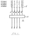
- Fig. 1 is a block diagram of an antenna system including a feed network in accordance with the invention.
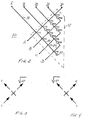
- Fig. 2 is a circuit diagram of an embodiment of the Fig. 1 feed network.
- Fig. 3 and Fig. 4 are diagrams useful in describing operating characteristics of directional couplers of the Fig. 2 feed network.
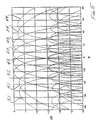
- Fig. 5 is a computed radiation pattern for the Fig. 2 feed network.
- a four channel Butler network may typically have four input beam ports coupled to four radiating elements, so that an input signal at any one of the beam ports results in an excitation of each of the radiating elements to produce one radiation pattern beam.
- the Butler network produces a differently phased and proportioned aperture output excitation for each beam port, resulting in four differently aimed beams for the four beam ports in this example.
- Such arrangements provide reciprocal operation for transmission and reception and, even though a cellular system may be used solely for reception in some applications, system operation may conveniently be described in terms of the signal relationships pertinent to transmission.
- Fig.1 is a block diagram of an antenna system utilizing a multi-beam antenna feed network in accordance with the present invention, in order to achieve low sidelobe lossless operation, via a four beam radiation pattern.
- a 4 x 4 Butler configuration provides lossless operation with sidelobes 12 dB down
- the 4 x 5 feed network of Fig. 1 provides lossless operation with sidelobes 15 dB down and certain other performance advantages to be discussed.
- the feed network 10 includes:
- the Fig. 1 configuration also includes five radiating elements of any suitable type, typically referenced at 14.
- feed arrangement 12 is responsive to beam port input signals to provide relative signal value outputs at the aperture ports as follows:
- These signal value outputs at aperture ports I-V represent orthogonal outputs having phase gradients effective to provide a four beam radiation pattern.
- feed arrangement 12 comprises directional coupler elements C11, C12, C13, C14, C21, C22, C23, C31, C32 and C41 and phase shift elements P22, P23, P24, P32, P33 and P41 intercoupled between the beam ports A-D and aperture ports I-V by transmission line sections.
- a typical line section intercoupling directional couplers is indicated at 16 and a typical line section coupling a directional coupler to an aperture port is indicated at 18.
- Figs. 3 and 4 identify the convention used for directional coupler circuit values.
- a unitary signal input at a lower left arm of a directional coupler results in a straight-through output signal value equal to the square root of the quantity 1-C 2 and also an output signal value at the normal arm equal to C.
- a unitary signal input at a lower right arm of a directional coupler results in a straight-through output signal value equal to the square root of the quantity 1-C 2 and also an output signal value at the normal arm equal to -C.
- the respective values for C of the directional couplers of Fig. 2 are as follows:
- Transmission line sections e.g., 16, 18 and 20
- Transmission line sections have a characteristic impedance of 50 ohms and one 50 ohm resistive termination is included in the feed network, at 22 in Fig. 2.
- beams 31, 32, 33 and 34 represent the first array antenna and beams 41, 42, 43 and 44 of the second array antenna (which is rotated slightly to radiate with a 15 degree angular offset) are superimposed.
- beam sets 31-33 and 41-43 each provide four 30 degree beams (width at -3 dB points) for coverage of a sector 120 degrees wide, with beam crossover at -5.24 dB (relative to peak). This performance is provided on a lossless basis with sidelobes more than 15 dB down. While not directly pertinent to this description, the use of two similar array antennae with angular offset enables cellular operation with both space diversity and angle diversity for improved area coverage and reliability of coverage.
- Computed performance factors for cellular communications applications are as follows: 4 x 4 Butler Fig. 2 Sidelobes -12 dB -15 dB Horizontal Pattern (1) directivity (dB) 6.0 7.0 (2) aperture efficiency (dB) 0.0 -0.1 (3) feed network loss (dB) -0.6 -0.6 (4) peak gain (dB) 5.4 6.3 (5) crossover level (dB) 1.7 1.1 (6) average gain (dB) 4.2 4.6 (7) range extension factor 1.27 1.30 (8) coverage area increase (%) 62 70 Interference Reduction (9) Maximum (dB) 6.0 6.9 (10) Average (dB) 4.8 5.2 (11) Minimum (dB) 2.3 1.7
- feed networks in accordance with the invention for cellular and other applications.
- Any suitable types and constructions of traditional or other forms of directional couplers, or other directional coupler elements, and phase shifters, or other phase shift elements, may be employed in modular or integrated form with appropriate transmission line elements. While a four by five feed network has been particularly described, the more aperture ports than beam ports design constraint pursuant to the invention can also be applied in feed networks with other than five aperture ports and four beam ports.
Landscapes
- Variable-Direction Aerials And Aerial Arrays (AREA)
Applications Claiming Priority (2)
| Application Number | Priority Date | Filing Date | Title |
|---|---|---|---|
| US08/725,105 US5856810A (en) | 1996-10-02 | 1996-10-02 | Low sidelobe multi-beam lossless feed networks for array antennas |
| US725105 | 1996-10-02 |
Publications (2)
| Publication Number | Publication Date |
|---|---|
| EP0834955A2 true EP0834955A2 (fr) | 1998-04-08 |
| EP0834955A3 EP0834955A3 (fr) | 2000-04-19 |
Family
ID=24913171
Family Applications (1)
| Application Number | Title | Priority Date | Filing Date |
|---|---|---|---|
| EP97307633A Withdrawn EP0834955A3 (fr) | 1996-10-02 | 1997-09-29 | Réseaux d'alimentation pour antennes |
Country Status (2)
| Country | Link |
|---|---|
| US (1) | US5856810A (fr) |
| EP (1) | EP0834955A3 (fr) |
Cited By (5)
| Publication number | Priority date | Publication date | Assignee | Title |
|---|---|---|---|---|
| WO1999036992A3 (fr) * | 1998-01-14 | 1999-10-07 | Raytheon Co | Antenne reseau a faisceaux multiples diriges independamment |
| RU2506670C2 (ru) * | 2012-05-11 | 2014-02-10 | Открытое акционерное общество "Научно-исследовательский институт приборостроения имени В.В. Тихомирова" | Фазированная антенная решетка |
| WO2017005145A1 (fr) * | 2015-07-03 | 2017-01-12 | 华为技术有限公司 | Réseau d'alimentation d'antenne à faisceaux multiples et ensemble d'antennes à faisceaux multiples |
| RU2757538C1 (ru) * | 2020-12-29 | 2021-10-18 | Федеральное Государственное Бюджетное Образовательное Учреждение Высшего Образования «Новосибирский Государственный Технический Университет» | Диаграммообразующее устройство |
| US20220342033A1 (en) * | 2019-08-26 | 2022-10-27 | Nxp B.V. | Mimo radar system |
Families Citing this family (2)
| Publication number | Priority date | Publication date | Assignee | Title |
|---|---|---|---|---|
| US6900775B2 (en) | 1997-03-03 | 2005-05-31 | Celletra Ltd. | Active antenna array configuration and control for cellular communication systems |
| AU6113198A (en) | 1997-03-03 | 1998-09-22 | Joseph Shapira | Method and system for improving communication |
Family Cites Families (9)
| Publication number | Priority date | Publication date | Assignee | Title |
|---|---|---|---|---|
| US3255450A (en) * | 1960-06-15 | 1966-06-07 | Sanders Associates Inc | Multiple beam antenna system employing multiple directional couplers in the leadin |
| US4176359A (en) * | 1977-07-18 | 1979-11-27 | Raytheon Company | Monopulse antenna system with independently specifiable patterns |
| US4321605A (en) * | 1980-01-29 | 1982-03-23 | Hazeltine Corporation | Array antenna system |
| US4689627A (en) * | 1983-05-20 | 1987-08-25 | Hughes Aircraft Company | Dual band phased antenna array using wideband element with diplexer |
| US4962383A (en) * | 1984-11-08 | 1990-10-09 | Allied-Signal Inc. | Low profile array antenna system with independent multibeam control |
| US5281974A (en) * | 1988-01-11 | 1994-01-25 | Nec Corporation | Antenna device capable of reducing a phase noise |
| US5125108A (en) * | 1990-02-22 | 1992-06-23 | American Nucleonics Corporation | Interference cancellation system for interference signals received with differing phases |
| IT1244907B (it) * | 1991-01-23 | 1994-09-13 | Selenia Spazio Spa Ora Alenia | Configurazione e tecnica di reti multimodali formatrici di fasci per antenne multifascio a riflettore. |
| FR2732163B1 (fr) * | 1995-03-20 | 1997-05-30 | Europ Agence Spatiale | Dispositif d'alimentation d'une antenne multisources et multifaisceaux |
-
1996
- 1996-10-02 US US08/725,105 patent/US5856810A/en not_active Expired - Fee Related
-
1997
- 1997-09-29 EP EP97307633A patent/EP0834955A3/fr not_active Withdrawn
Cited By (8)
| Publication number | Priority date | Publication date | Assignee | Title |
|---|---|---|---|---|
| WO1999036992A3 (fr) * | 1998-01-14 | 1999-10-07 | Raytheon Co | Antenne reseau a faisceaux multiples diriges independamment |
| US6104343A (en) * | 1998-01-14 | 2000-08-15 | Raytheon Company | Array antenna having multiple independently steered beams |
| US6232920B1 (en) | 1998-01-14 | 2001-05-15 | Raytheon Company | Array antenna having multiple independently steered beams |
| RU2506670C2 (ru) * | 2012-05-11 | 2014-02-10 | Открытое акционерное общество "Научно-исследовательский институт приборостроения имени В.В. Тихомирова" | Фазированная антенная решетка |
| WO2017005145A1 (fr) * | 2015-07-03 | 2017-01-12 | 华为技术有限公司 | Réseau d'alimentation d'antenne à faisceaux multiples et ensemble d'antennes à faisceaux multiples |
| US20220342033A1 (en) * | 2019-08-26 | 2022-10-27 | Nxp B.V. | Mimo radar system |
| US12287423B2 (en) * | 2019-08-26 | 2025-04-29 | Nxp B.V. | MIMO radar system |
| RU2757538C1 (ru) * | 2020-12-29 | 2021-10-18 | Федеральное Государственное Бюджетное Образовательное Учреждение Высшего Образования «Новосибирский Государственный Технический Университет» | Диаграммообразующее устройство |
Also Published As
| Publication number | Publication date |
|---|---|
| EP0834955A3 (fr) | 2000-04-19 |
| US5856810A (en) | 1999-01-05 |
Similar Documents
| Publication | Publication Date | Title |
|---|---|---|
| US6529166B2 (en) | Ultra-wideband multi-beam adaptive antenna | |
| US5561434A (en) | Dual band phased array antenna apparatus having compact hardware | |
| US4989011A (en) | Dual mode phased array antenna system | |
| US5854611A (en) | Power shared linear amplifier network | |
| CN106602265B (zh) | 波束成形网络及其输入结构、输入输出方法及三波束天线 | |
| CN1150662C (zh) | 天线孔径可任意利用的集成发射/接收天线 | |
| CA2076990C (fr) | Antenne microruban a fentes a balayage electronique | |
| EP0253465B1 (fr) | Formage des diagrammes de rayonnement dans un système d'antenne | |
| JP4034265B2 (ja) | 2個の放射要素を備えるリアクティブ結合アンテナ | |
| US6225947B1 (en) | Butler beam port combining for hexagonal cell coverage | |
| JP2001500691A (ja) | ワイヤレス基地局のカバレージ領域、範囲及び信頼度強化用のアンテナシステム | |
| US20040135732A1 (en) | Dual port helical-dipole antenna and array | |
| EP0307445A1 (fr) | Reseau de formation de faisceaux a niveaux multiples. | |
| Fakoukakis et al. | Novel Nolen matrix based beamforming networks for series-fed low SLL multibeam antennas | |
| US6057806A (en) | Cross-polarized around-tower cellular antenna systems | |
| WO2025235650A1 (fr) | Agencement d'antenne à quatre polarisations | |
| US5856810A (en) | Low sidelobe multi-beam lossless feed networks for array antennas | |
| US6504505B1 (en) | Phase control network for active phased array antennas | |
| Alam | Microstrip antenna array with four port butler matrix for switched beam base station application | |
| US6353410B1 (en) | Space tapered antenna having compressed spacing or feed network phase progression, or both | |
| Mandloi et al. | 4x4 Butler Matrix Design for Multibeam Operation for Radar Application | |
| CN211150769U (zh) | 天线组件以及具有天线组件的基站天线 | |
| US20030214438A1 (en) | Broadband I-slot microstrip patch antenna | |
| Sor et al. | Multi-mode microstrip antennas for reconfigurable aperture | |
| CN113659354A (zh) | 一种基于横跨定向耦合线的3×3诺伦矩阵 |
Legal Events
| Date | Code | Title | Description |
|---|---|---|---|
| PUAI | Public reference made under article 153(3) epc to a published international application that has entered the european phase |
Free format text: ORIGINAL CODE: 0009012 |
|
| AK | Designated contracting states |
Kind code of ref document: A2 Designated state(s): AT BE CH DE DK ES FI FR GB GR IE IT LI LU MC NL PT SE |
|
| AX | Request for extension of the european patent |
Free format text: AL;LT;LV;RO;SI |
|
| PUAL | Search report despatched |
Free format text: ORIGINAL CODE: 0009013 |
|
| AK | Designated contracting states |
Kind code of ref document: A3 Designated state(s): AT BE CH DE DK ES FI FR GB GR IE IT LI LU MC NL PT SE |
|
| AX | Request for extension of the european patent |
Free format text: AL;LT;LV;RO;SI |
|
| AKX | Designation fees paid | ||
| REG | Reference to a national code |
Ref country code: DE Ref legal event code: 8566 |
|
| STAA | Information on the status of an ep patent application or granted ep patent |
Free format text: STATUS: THE APPLICATION IS DEEMED TO BE WITHDRAWN |
|
| 18D | Application deemed to be withdrawn |
Effective date: 20001020 |