EP0834960A2 - Steckdose - Google Patents
Steckdose Download PDFInfo
- Publication number
- EP0834960A2 EP0834960A2 EP97116424A EP97116424A EP0834960A2 EP 0834960 A2 EP0834960 A2 EP 0834960A2 EP 97116424 A EP97116424 A EP 97116424A EP 97116424 A EP97116424 A EP 97116424A EP 0834960 A2 EP0834960 A2 EP 0834960A2
- Authority
- EP
- European Patent Office
- Prior art keywords
- locking
- support body
- socket
- contact insert
- insert
- Prior art date
- Legal status (The legal status is an assumption and is not a legal conclusion. Google has not performed a legal analysis and makes no representation as to the accuracy of the status listed.)
- Granted
Links
Images


Classifications
-
- H—ELECTRICITY
- H01—ELECTRIC ELEMENTS
- H01R—ELECTRICALLY-CONDUCTIVE CONNECTIONS; STRUCTURAL ASSOCIATIONS OF A PLURALITY OF MUTUALLY-INSULATED ELECTRICAL CONNECTING ELEMENTS; COUPLING DEVICES; CURRENT COLLECTORS
- H01R13/00—Details of coupling devices of the kinds covered by groups H01R12/70 or H01R24/00 - H01R33/00
- H01R13/46—Bases; Cases
- H01R13/502—Bases; Cases composed of different pieces
- H01R13/506—Bases; Cases composed of different pieces assembled by snap action of the parts
-
- H—ELECTRICITY
- H01—ELECTRIC ELEMENTS
- H01R—ELECTRICALLY-CONDUCTIVE CONNECTIONS; STRUCTURAL ASSOCIATIONS OF A PLURALITY OF MUTUALLY-INSULATED ELECTRICAL CONNECTING ELEMENTS; COUPLING DEVICES; CURRENT COLLECTORS
- H01R13/00—Details of coupling devices of the kinds covered by groups H01R12/70 or H01R24/00 - H01R33/00
- H01R13/66—Structural association with built-in electrical component
- H01R13/70—Structural association with built-in electrical component with built-in switch
- H01R13/703—Structural association with built-in electrical component with built-in switch operated by engagement or disengagement of coupling parts, e.g. dual-continuity coupling part
- H01R13/7035—Structural association with built-in electrical component with built-in switch operated by engagement or disengagement of coupling parts, e.g. dual-continuity coupling part comprising a separated limit switch
-
- H—ELECTRICITY
- H01—ELECTRIC ELEMENTS
- H01R—ELECTRICALLY-CONDUCTIVE CONNECTIONS; STRUCTURAL ASSOCIATIONS OF A PLURALITY OF MUTUALLY-INSULATED ELECTRICAL CONNECTING ELEMENTS; COUPLING DEVICES; CURRENT COLLECTORS
- H01R24/00—Two-part coupling devices, or either of their cooperating parts, characterised by their overall structure
- H01R24/76—Two-part coupling devices, or either of their cooperating parts, characterised by their overall structure with sockets, clips or analogous contacts and secured to apparatus or structure, e.g. to a wall
-
- H—ELECTRICITY
- H01—ELECTRIC ELEMENTS
- H01R—ELECTRICALLY-CONDUCTIVE CONNECTIONS; STRUCTURAL ASSOCIATIONS OF A PLURALITY OF MUTUALLY-INSULATED ELECTRICAL CONNECTING ELEMENTS; COUPLING DEVICES; CURRENT COLLECTORS
- H01R2107/00—Four or more poles
-
- H—ELECTRICITY
- H01—ELECTRIC ELEMENTS
- H01R—ELECTRICALLY-CONDUCTIVE CONNECTIONS; STRUCTURAL ASSOCIATIONS OF A PLURALITY OF MUTUALLY-INSULATED ELECTRICAL CONNECTING ELEMENTS; COUPLING DEVICES; CURRENT COLLECTORS
- H01R2201/00—Connectors or connections adapted for particular applications
- H01R2201/26—Connectors or connections adapted for particular applications for vehicles
Definitions
- the invention relates to a socket for multipole Plug devices, in particular for the electrical connection a motor vehicle trailer, with a can housing and contact carrier insert provided therein for the reception of contacts to be provided with electrical connection lines, which a contact insert and a receiving, in snap into the socket housing or connected to it
- Support body e.g. with a seal against the can housing, has, on which preferably rear support parts Connect for support on the mounting surface.
- Such a socket is known from DE-GM 90 06 443. This is intended to connect the electrical conductors of the the socket leading conductor strand with the socket be relieved. This will support the contact insert on the mounting surface as well as fitting it taken over into the socket housing by the support body.
- the first purpose is to insert the contact into the passage opening insert a receiving section of the support body, after which lateral support sections on the back of the Receiving section can be folded down. The resulting The unit of contact insert and support body is then inserted into the box housing.
- the Assembly site for example on a motor vehicle trailer, each Allocate and insert contacts into any contact chambers and their locking, so that corresponding Errors due to confusion and the like are excluded are.
- it is still a considerable assembly effort required at the assembly site because of the supporting body and Contact insert assembled by different manipulations must be before the resulting unit in the Can housing can be inserted.
- the object of the present invention is the known To further develop the socket so that the assembly effort for the Socket and the connection of the wiring harness on site and Digit is reduced.
- This object is essentially achieved according to the invention solved that the contact insert in the already in the socket housing inserted or firmly connected to it Support body is clickable.
- Assembly on the spot takes place in the socket according to the invention in the Way that the socket housing from the socket manufacturer delivered pre-assembled with the support body which is either already detachable in the can housing is engaged or firmly connected to the latter.
- the contact insert in the already in existing support body snapped into place will.
- the detachable already made by the manufacturer Snap the support body into the socket housing to prefer the support body firmly connected to the socket housing, because in this way a sealing of the Contact carrier insert against the socket housing easier can be accomplished; in this case, namely Sealing carried by the support body and snapping into place of the support body in the box housing in the required Be positioned way.
- the support body has a further development of the inventive concept preferably at its rear edge several over the circumference distributed, when inserting the contact insert axially into the Support body elastically evasive and in the locked position snap-back snap hooks for the contact insert. To this Way is by merely axially inserting the contact insert Safe locking possible in the support body. Through the Distribution of a number of locking hooks over the circumference of the Support body can also have the required tensile forces be included, so that there is a risk that the contact insert unintentionally releases from the support body, is eliminated.
- Newer sockets of the generic type such as the DE-GM 92 07 523 known, have in addition to the contact carrier insert a microswitch on which a separate Additional plug with connecting cables can be connected.
- a microswitch is used for the optional connection of other functions, for example of fog lamps. It can too two or more such microswitches can be provided, which in the corresponding slots in the socket housing are included, in which corresponding additional plug fit.
- the invention is optional for such equipped with microswitch socket suggested that at least one of the locking hooks designed as locking hooks which is the insertion of the additional plug into the Prevents space when the contact insert is incomplete is inserted into the support body. This is done an additional check for the correct seat of the Contact insert in the support body and thus in the socket housing.
- At least one of the locking hooks is designed as a locking hook which is an insertion of the contact insert into the Support body prevented when the additional plug in the Slot is inserted. This ensures that the fitter always first the additional plug in the support body and thus the socket housing snaps into place then the smaller additional plug into the slot for the Introduces connection with the microswitch so that a excessive strain on the cable connections is avoided.
- the respective trained as a locking hook Locking hook with a radially inwardly projecting locking projection to the back of the box housing pointing slope for has the contact insert. If the additional plug already is inserted into its slot and thus the locking hook are prevented from inserting the contact insert after To avoid elastic radially outside, the locking projections are the complete insertion of the contact insert into the Can housing in the way. This ensures that Always the contact insert first and only then the additional plug be inserted into the can housing.
- the respective locking hooks have a locking projection, which a locking edge pointing towards the front of the can housing which is slightly inward towards a radial plane is inclined.
- one or more of the locking hooks Device for locking in their locked position assigned which is inevitable when mounting on a mounting plate is effective. With such a configuration, it will Radial evasion of the locking hook from the contact insert prevents locking position securing in the socket housing, too if there is no additional plug.
- Said locking device for the locking hook can in special configuration one on an elastically flexible Arm of the support body bearing projection, which before mounting on the mounting plate via the mounting side End of the support body and the can housing protrudes and with Help with that when mounting the arm pressed into one position is in which a radial evasion of the locking hook is prevented.
- the socket shown in the drawings for a Multipole plug device has a socket housing 1 and one contact carrier insert 2 to be provided therein for the reception of to be provided with electrical connection lines 3 Contacts.
- the contact carrier insert 2 consists of a Contact insert 6 and a receiving this in the Can housing 1 snap or firmly connected Support body 4.
- the support body 4 carries at its front end a seal 7 against the can housing 1.
- the support body 4 can also rear support parts 5 for support on the later mounting surface, so that the (not shown) Snap connection between support body 4 and box housing 1 when inserting a plug into the socket is not overused.
- the contact insert 6 is already in the socket housing 1 latched support body 4 can be snapped into place.
- the support body 4 has several at its rear edge 8 in the illustrated case six, distributed over the scope, at axial insertion of the contact insert 6 into the support body 4 to be deflected radially outward and in the locked position snap-back snap hooks 9, 9 'for the contact insert 6 on.
- the latching position engages behind the latching hooks 9, 9 ' rear edge of the contact insert 6 by means of radially inward pointing locking projections 14 to the contact insert 6 in the Support body 4 and thus to keep the box housing 1.
- the Locking projections 14 each have a front of the Can housing 1 facing locking edge 16, which preferably to a radial plane are inclined slightly inwards forward so that when tensile forces occur on the contact carrier 6 Dodge locking hooks 9, 9 'less easily to the outside.
- Locking hook 9 designed as locking hook 9 '.
- the left one Locking hook 9 ' is not (yet) in the drawings Assigned microswitch 11, but this can be done if necessary could.
- the respective locking hook 9 'prevents from 2a shows the insertion of the additional plug 12 in the slot 10 when the contact insert 6 is incomplete the support body 4 is inserted. In this incomplete introduced position of the contact insert 6 can Locking hook 9, and thus the locking hook 9 'not in their Snap the locking position back inward so that one is facing outwards protruding locking projection 13 of the locking hook 9 'still in the The slot 10 for the additional connector 12 protrudes, and so that cannot be inserted into the slot 10.
- the radial takes place Deflection of the locking hooks 9, 9 'by the interaction of one Circumferential edge 17 of the contact insert 6 at its axial Insert with rear ramp 15 of the locking hook 9, 9 '. If, as illustrated in Fig. 4, an auxiliary connector 12 has already been inserted into the slot 10 can the respective locking hooks 9 'are not radially outward dodge since the additional plug 12 is in the way. On the other hand prevent the inward facing locking projections 14 further inserting the contact insert 6 into the socket housing 1 beyond the intermediate position shown in FIG. 4. On This ensures that the contact insert is used first 6 and only then the additional plug 12 into the socket housing 1 is to be introduced.
- the locking hooks 9 'therefore have a multiple function: they not only act when the contact insert 6 is locked with the Can housing 1 with, they also pose when inserting a Additional connector 12 ensure that the contact insert 6 beforehand completely brought into its final resting position is, they prevent the additional plug 12 and only then the contact insert 6 is inserted into the socket housing 1 and they make it difficult to release the contact insert 6 from the latching when tensile forces occur when a Additional plug 12 is inserted because the locking hook 9 'for do not dodge this case radially outwards can.
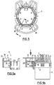
- FIG. 5 shows one seen from the mounting plate 19 Support body 4 according to another embodiment of the invention.
- the support body 4 has here distributed over the circumference Locking hook 9 on which the contact insert 6 according to Fig. 5b after its complete insertion into the support body 4 reach behind by means of locking edges 16.
- a locking device 18 is provided, which when mounting the socket on a mounting plate 19 inevitably takes effect.
- the locking device 18 has an embodiment one on the support body 4 pointing radially inwards elastic arm 20, which carries a projection 21.
- the projection 21 protrudes in front of the Mounting on the mounting plate 19 via the rear edge 22 of the support body 4 (or in a manner not shown above the rear edge of the can housing).
- the lead 21 is on an elastically evasive, essentially radial arm 20 held.
- Fig. 5b gives way the projection 21 then due to the assembly of the socket the elasticity of the arms 20. In this way it gets there free end of the arm 20 directly to the back of the respective locking hook 9, so that it does not move radially can move outside.
- the lock is removed again.
Landscapes
- Connector Housings Or Holding Contact Members (AREA)
- Details Of Connecting Devices For Male And Female Coupling (AREA)
- Motor Or Generator Frames (AREA)
Abstract
Description
- Fig. 1
- teilweise geschnitten eine die Erfindung aufweisende Steckdose, wobei der Stützkörper bereits in das Dosengehäuse eingerastet bzw. mit diesem fest verbunden ist, während Kontakteinsatz und Zusatzstecker sich noch in geringem Abstand hinter dem Dosengehäuse kurz vor dem Einstecken befinden,
- Fig. 2a
- die Steckdose gemäß Fig. 1, bei welcher der Kontakteinsatz nur unvollständig in den Stützkörper eingeführt ist und versucht wird, den Zusatzstecker in seinen Steckraum einzuschieben,
- Fig. 2b
- die Steckdose von Fig. 2a von hinten gesehen (ohne Anschlußleitungen und Zusatzstecker),
- Fig. 3a
- eine Steckdose gemäß Fig. 1, bei welcher der Kontakteinsatz sich in seiner endgültigen Rastposition in dem Stützkörper befindet und der Zusatzstecker in seinen Steckraum eingeführt ist,
- Fig. 3b
- eine Darstellung entsprechend Fig. 2b für die Steckdosenkonstellation nach Fig. 3a,
- Fig. 4
- die Steckdose nach Fig. 1, bei welcher zunächst der Zusatzstecker in seinen Steckraum eingeführt worden ist und versucht wird, den Kontakteinsatz vollständig in den Stützkörper einzuführen,
- Fig. 5
- einen Stützkörper gemäß einer anderen Ausgestaltung der Erfindung, von der Montageplatte aus gesehen,
- Fig. 5a
- einen Schnitt entsprechend der Schnittlinie a von Fig. 5, teilweise weggebrochen, und
- Fig. 5b
- einen Schnitt entsprechend Fig. 5a, wobei jedoch in den Stützkörper ein Kontakteinsatz 6 in seine endgültige Rastposition innerhalb des Stützkörpers eingeführt worden ist.
- 1
- Dosengehäuse
- 2
- Kontaktträgereinsatz
- 3, 3'
- Anschlußleitungen
- 4
- Stützkörper
- 5
- Stützteile
- 6
- Kontakteinsatz
- 7
- Abdichtung
- 8
- Rand
- 9
- Rasthaken
- 9'
- Sperrasthaken
- 10
- Steckraum
- 11
- Mikroschalter
- 12
- Zusatzstecker
- 13
- Sperrvorsprung
- 14
- Rastvorsprung
- 15
- Auflaufschräge
- 16
- Rastkante
- 17
- Umlaufkante
- 18
- Arretiereinrichtung
- 19
- Montageplatte
- 20
- Arm
- 21
- Vorsprung
- 22
- Kante
Claims (9)
- Steckdose für mehrpolige Steckvorrichtungen, insbesondere für den elektrischen Anschluß eines Kraftfahrzeuganhängers, mit einem Dosengehäuse (1) und einem darin vorgesehenen Kontaktträgereinsatz (2) für die Aufnahme von mit elektrischen Anschlußleitungen (3) zu versehenden Kontakten, welche einen Kontakteinsatz (6) und einen diesen aufnehmenden, in dem Dosengehäuse (1) einrastbaren oder mit diesem verbundenen Stützkörper (4), z.B. mit einer Abdichtung (7) gegen das Dosengehäuse (1), aufweist, an welchem sich vorzugsweise rückwärtige Stützteile (5) zur Abstützung auf der Montagefläche anschließen, dadurch gekennzeichnet, daß der Kontakteinsatz (6) in den bereits in das Dosengehäuse (1) eingerasteten oder mit diesem festverbundenen Stützkörper (4) einrastbar ist.
- Steckdose nach Anspruch 1, dadurch gekennzeichnet, daß der Stützkörper (4) an seinem hinteren Rand (8) mehrere über den Umfang verteilte, beim axialen Einführen des Kontakteinsatzes (6) in den Stützkörper (4) elastisch ausweichende und in Raststellung zurückschnappende Rasthaken (9, 9') für den Kontakteinsatz (6) aufweist.
- Steckdose nach Anspruch 2, mit wenigstens einem gesonderten Steckraum (10) in dem Dosengehäuse (1) neben dem Kontaktträgereinsatz (2) für die Aufnahme eines Mikroschalters (11) und eines daran anschließbaren Zusatzsteckers (12), dadurch gekennzeichnet, daß wenigstens einer der Rasthaken (9) als Sperrasthaken (9') ausgebildet ist, welcher das Einstecken des Zusatzsteckers (12) in den Steckraum (10) verhindert, wenn der Kontakteinsatz (6) unvollständig in den Stützkörper (4) eingesteckt ist.
- Steckdose nach Anspruch 2 oder 3, dadurch gekennzeichnet, daß wenigstens einer der Rasthaken (9) als Sperrasthaken (9') ausgebildet ist, welcher ein Einstecken des Kontakteinsatzes (6) in den Stützkörper (4) verhindert, wenn der Zusatzstecker (12) in den Steckraum (10) eingesteckt ist.
- Steckdose nach Anspruch 3 oder 4, dadurch gekennzeichnet, daß der jeweilige als Sperrasthaken (9') ausgebildete Rasthaken (9) einen radial nach außen ragenden Sperrvorsprung (13) hat, welcher bei Auslenkung des Rasthakens (9) nach radial außen in den Steckraum (10) für den Zusatzstecker (12) ragt.
- Steckdose nach einem der Ansprüche 3 bis 5, dadurch gekennzeichnet, daß der jeweilige als Sperrasthaken (9') ausgebildete Rasthaken (9) einen radial nach innen ragenden Rastvorsprung (14) mit zur Rückseite des Dosengehäuses (1) weisenden Auflaufschräge (15) für den Kontakteinsatz (6) aufweist.
- Steckdose nach einem der Ansprüche 2 bis 6, dadurch gekennzeichnet, daß der jeweilige Rasthaken (9, 9') einen Rastvorsprung (14) aufweist, welcher eine zur Vorderseite des Dosengehäuses (1) weisende Rastkante (16) aufweist, welche zu einer Radialebene leicht nach innen vorne geneigt ist.
- Steckdose nach einem der Ansprüche 1 bis 7, dadurch gekennzeichnet, daß einem oder mehreren der Rasthaken (9, 9') eine Einrichtung zum Arretieren (18) in deren Rastposition zugeordnet ist, welche durch die Montage auf einer Montageplatte (19) zwangsläufig wirksam ist.
- Steckdose nach Anspruch 8, dadurch gekennzeichnet, daß die Arretiereinrichtung (18) für die Rasthaken (9, 9') einen an einem elastisch nachgiebigen Arm (20) des Stützkörpers (4) gelagerten Vorsprung (21) aufweist, welcher vor der Montage auf der Montageplatte (19) über das montageseitige Ende des Stützkörpers (4) und des Dosengehäuses (1) hinausragt und mit Hilfe dessen bei der Montage der Arm (20) in eine Lage gedrückt wird, in welcher ein radiales Ausweichen der Rasthaken verhindert ist.
Applications Claiming Priority (4)
| Application Number | Priority Date | Filing Date | Title |
|---|---|---|---|
| DE29617325U | 1996-10-07 | ||
| DE29617325 | 1996-10-07 | ||
| DE29618000U DE29618000U1 (de) | 1996-10-07 | 1996-10-16 | Steckdose |
| DE29618000U | 1996-10-16 |
Publications (3)
| Publication Number | Publication Date |
|---|---|
| EP0834960A2 true EP0834960A2 (de) | 1998-04-08 |
| EP0834960A3 EP0834960A3 (de) | 1998-10-14 |
| EP0834960B1 EP0834960B1 (de) | 2002-03-20 |
Family
ID=26059497
Family Applications (1)
| Application Number | Title | Priority Date | Filing Date |
|---|---|---|---|
| EP97116424A Expired - Lifetime EP0834960B1 (de) | 1996-10-07 | 1997-09-20 | Steckdose |
Country Status (1)
| Country | Link |
|---|---|
| EP (1) | EP0834960B1 (de) |
Cited By (5)
| Publication number | Priority date | Publication date | Assignee | Title |
|---|---|---|---|---|
| EP0982811A3 (de) * | 1998-08-21 | 2000-10-04 | ERICH JAEGER GmbH & Co. KG | Steckdose für mehrpolige Steckverbindung |
| EP1686659A1 (de) * | 2005-01-31 | 2006-08-02 | ERICH JAEGER GmbH & Co. KG | Steckdose |
| EP2019458A3 (de) * | 2007-07-27 | 2010-08-25 | ConWys AG | Steckdose, insbesondere Anhänger-Steckdose |
| EP2249438A3 (de) * | 2009-05-06 | 2011-05-11 | ConWys AG | Steckdose für eine mehrpolige Steckverbindung |
| WO2020011309A1 (de) * | 2018-07-13 | 2020-01-16 | HARTING Customised Solutions GmbH & Co. KG | Funktionales steckverbindermodul |
Family Cites Families (4)
| Publication number | Priority date | Publication date | Assignee | Title |
|---|---|---|---|---|
| US3671921A (en) * | 1970-10-28 | 1972-06-20 | Amp Inc | Multi-contact electrical connector |
| DE7812822U1 (de) * | 1978-04-27 | 1978-10-12 | Erich Jaeger Kg, 6380 Bad Homburg | Steckdose für mehrpolige Steckvorrichtung |
| DE9006443U1 (de) * | 1990-06-07 | 1990-08-23 | Erich Jaeger GmbH & Co KG, 6380 Bad Homburg | Steckdose für mehrpolige Steckvorrichtung |
| TW201853B (en) * | 1992-02-24 | 1993-03-11 | Amp Inc | Shielded data connector |
-
1997
- 1997-09-20 EP EP97116424A patent/EP0834960B1/de not_active Expired - Lifetime
Cited By (5)
| Publication number | Priority date | Publication date | Assignee | Title |
|---|---|---|---|---|
| EP0982811A3 (de) * | 1998-08-21 | 2000-10-04 | ERICH JAEGER GmbH & Co. KG | Steckdose für mehrpolige Steckverbindung |
| EP1686659A1 (de) * | 2005-01-31 | 2006-08-02 | ERICH JAEGER GmbH & Co. KG | Steckdose |
| EP2019458A3 (de) * | 2007-07-27 | 2010-08-25 | ConWys AG | Steckdose, insbesondere Anhänger-Steckdose |
| EP2249438A3 (de) * | 2009-05-06 | 2011-05-11 | ConWys AG | Steckdose für eine mehrpolige Steckverbindung |
| WO2020011309A1 (de) * | 2018-07-13 | 2020-01-16 | HARTING Customised Solutions GmbH & Co. KG | Funktionales steckverbindermodul |
Also Published As
| Publication number | Publication date |
|---|---|
| EP0834960A3 (de) | 1998-10-14 |
| EP0834960B1 (de) | 2002-03-20 |
Similar Documents
| Publication | Publication Date | Title |
|---|---|---|
| DE60100320T2 (de) | Aufbau verriegelbarer Verbinder | |
| DE60115979T2 (de) | Elektrischer verbinder mit einstückiger Verriegelungs- und Zugentlastungsvorrichtung | |
| DE69934065T2 (de) | Elektrischer Kontakt für Verbinder mit Kodierrippe | |
| DE69701476T2 (de) | Elektrische Anschlussbuchse | |
| EP0212330B1 (de) | Anschluss- bzw. Verbindungsklemme für elektrische Geräte | |
| DE102017113875B3 (de) | Elektrischer Stecker mit einem Schutzleiterkontakt und damit einstückig ausgebildeten Schutzleiterverbindungselement zur Erdung von Außenteilen | |
| DE2316582A1 (de) | Elektrisches verbindungsstueck | |
| EP0111245B1 (de) | Verriegelbare elektrische Flachsteckbuchse und damit versehener elektrischer Verbinder | |
| WO2014001206A1 (de) | Stecker mit kontaktbuchse und schutzabdeckung | |
| WO2013056696A1 (de) | Steckverbinder | |
| DE102017110384A1 (de) | Verbinderstecker mit werkzeugloser Stifteinsatzdemontage | |
| DE1919425A1 (de) | Elektrischer Anschluss oder elektrische Verbindung wie beispielsweise Steckverbindung | |
| DE102011002135A1 (de) | Steckerelement mit zweiter Kontaktsicherung | |
| EP0834960B1 (de) | Steckdose | |
| EP1528639B1 (de) | Steckverbindergehäuse mit Kurzschlussbrücke | |
| DE4433617C2 (de) | Elektrisches Steckverbindungsteil | |
| DE2413445C2 (de) | Elektrischer Zwittersteckverbinder | |
| DE29618000U1 (de) | Steckdose | |
| EP0327701B1 (de) | Steckdose bzw. Stecker für mehrpolige elektrische Steckvorrichtung | |
| DE1590041A1 (de) | Isoliergehaeuse zum Einsetzen in eine OEffnung der Schalttafel eines Klinkenfeldes und zur Aufnahme von zwei satt aneinanderliegenden elektrischen Verbindungselementen | |
| EP1720222B1 (de) | Steckverbinder, insbesondere für Airbag-Zündsysteme | |
| DE10027094A1 (de) | Befestigte Struktur einer steckerseitigen Abdeckung | |
| EP1206008B1 (de) | Steckverbinder zum Anschliessen elektrischer Leitungen an eine elektrische Vorrichtung, insbesondere einen Motor | |
| EP1587175B1 (de) | Verbinder für signalübertragende Kabel | |
| DE4102681C2 (de) | Grundkörper für Steckdosen und Stecker |
Legal Events
| Date | Code | Title | Description |
|---|---|---|---|
| PUAI | Public reference made under article 153(3) epc to a published international application that has entered the european phase |
Free format text: ORIGINAL CODE: 0009012 |
|
| AK | Designated contracting states |
Kind code of ref document: A2 Designated state(s): DE FR GB IT NL SE |
|
| ITCL | It: translation for ep claims filed |
Representative=s name: BUGNION S.P.A. |
|
| GBC | Gb: translation of claims filed (gb section 78(7)/1977) | ||
| EL | Fr: translation of claims filed | ||
| TCNL | Nl: translation of patent claims filed | ||
| PUAL | Search report despatched |
Free format text: ORIGINAL CODE: 0009013 |
|
| AK | Designated contracting states |
Kind code of ref document: A3 Designated state(s): AT BE CH DE DK ES FI FR GB GR IE IT LI LU MC NL PT SE |
|
| 17P | Request for examination filed |
Effective date: 19981103 |
|
| AKX | Designation fees paid |
Free format text: DE FR GB IT NL SE |
|
| 17Q | First examination report despatched |
Effective date: 19990705 |
|
| GRAG | Despatch of communication of intention to grant |
Free format text: ORIGINAL CODE: EPIDOS AGRA |
|
| GRAG | Despatch of communication of intention to grant |
Free format text: ORIGINAL CODE: EPIDOS AGRA |
|
| GRAH | Despatch of communication of intention to grant a patent |
Free format text: ORIGINAL CODE: EPIDOS IGRA |
|
| GRAH | Despatch of communication of intention to grant a patent |
Free format text: ORIGINAL CODE: EPIDOS IGRA |
|
| REG | Reference to a national code |
Ref country code: GB Ref legal event code: IF02 |
|
| GRAA | (expected) grant |
Free format text: ORIGINAL CODE: 0009210 |
|
| AK | Designated contracting states |
Kind code of ref document: B1 Designated state(s): DE FR GB IT NL SE |
|
| REF | Corresponds to: |
Ref document number: 59706658 Country of ref document: DE Date of ref document: 20020425 |
|
| RAP2 | Party data changed (patent owner data changed or rights of a patent transferred) |
Owner name: ERICH JAEGER GMBH & CO. KG |
|
| NLT2 | Nl: modifications (of names), taken from the european patent patent bulletin |
Owner name: ERICH JAEGER GMBH & CO. KG |
|
| ET | Fr: translation filed | ||
| REG | Reference to a national code |
Ref country code: FR Ref legal event code: CA |
|
| PLBE | No opposition filed within time limit |
Free format text: ORIGINAL CODE: 0009261 |
|
| STAA | Information on the status of an ep patent application or granted ep patent |
Free format text: STATUS: NO OPPOSITION FILED WITHIN TIME LIMIT |
|
| 26N | No opposition filed |
Effective date: 20021223 |
|
| REG | Reference to a national code |
Ref country code: FR Ref legal event code: PLFP Year of fee payment: 19 |
|
| PGFP | Annual fee paid to national office [announced via postgrant information from national office to epo] |
Ref country code: GB Payment date: 20150922 Year of fee payment: 19 |
|
| PGFP | Annual fee paid to national office [announced via postgrant information from national office to epo] |
Ref country code: FR Payment date: 20150923 Year of fee payment: 19 Ref country code: SE Payment date: 20150922 Year of fee payment: 19 |
|
| PGFP | Annual fee paid to national office [announced via postgrant information from national office to epo] |
Ref country code: IT Payment date: 20150925 Year of fee payment: 19 |
|
| PGFP | Annual fee paid to national office [announced via postgrant information from national office to epo] |
Ref country code: NL Payment date: 20150923 Year of fee payment: 19 |
|
| PGFP | Annual fee paid to national office [announced via postgrant information from national office to epo] |
Ref country code: DE Payment date: 20161124 Year of fee payment: 20 |
|
| PG25 | Lapsed in a contracting state [announced via postgrant information from national office to epo] |
Ref country code: SE Free format text: LAPSE BECAUSE OF NON-PAYMENT OF DUE FEES Effective date: 20160921 |
|
| REG | Reference to a national code |
Ref country code: SE Ref legal event code: EUG |
|
| REG | Reference to a national code |
Ref country code: NL Ref legal event code: MM Effective date: 20161001 |
|
| GBPC | Gb: european patent ceased through non-payment of renewal fee |
Effective date: 20160920 |
|
| PG25 | Lapsed in a contracting state [announced via postgrant information from national office to epo] |
Ref country code: NL Free format text: LAPSE BECAUSE OF NON-PAYMENT OF DUE FEES Effective date: 20161001 |
|
| REG | Reference to a national code |
Ref country code: FR Ref legal event code: ST Effective date: 20170531 |
|
| PG25 | Lapsed in a contracting state [announced via postgrant information from national office to epo] |
Ref country code: FR Free format text: LAPSE BECAUSE OF NON-PAYMENT OF DUE FEES Effective date: 20160930 Ref country code: GB Free format text: LAPSE BECAUSE OF NON-PAYMENT OF DUE FEES Effective date: 20160920 |
|
| PG25 | Lapsed in a contracting state [announced via postgrant information from national office to epo] |
Ref country code: IT Free format text: LAPSE BECAUSE OF NON-PAYMENT OF DUE FEES Effective date: 20160920 |
|
| REG | Reference to a national code |
Ref country code: DE Ref legal event code: R071 Ref document number: 59706658 Country of ref document: DE |