EP0835010B1 - System zur Verkehrssteuerung und Überlastregelung für Paketnetzwerke - Google Patents
System zur Verkehrssteuerung und Überlastregelung für Paketnetzwerke Download PDFInfo
- Publication number
- EP0835010B1 EP0835010B1 EP97402266A EP97402266A EP0835010B1 EP 0835010 B1 EP0835010 B1 EP 0835010B1 EP 97402266 A EP97402266 A EP 97402266A EP 97402266 A EP97402266 A EP 97402266A EP 0835010 B1 EP0835010 B1 EP 0835010B1
- Authority
- EP
- European Patent Office
- Prior art keywords
- packets
- information
- virtual connection
- cuf
- packet
- Prior art date
- Legal status (The legal status is an assumption and is not a legal conclusion. Google has not performed a legal analysis and makes no representation as to the accuracy of the status listed.)
- Expired - Lifetime
Links
- 230000005540 biological transmission Effects 0.000 claims abstract description 27
- 238000000034 method Methods 0.000 claims abstract description 16
- 238000004891 communication Methods 0.000 claims description 36
- 238000005259 measurement Methods 0.000 claims description 9
- 238000011144 upstream manufacturing Methods 0.000 claims description 6
- 208000027744 congestion Diseases 0.000 description 50
- 238000007726 management method Methods 0.000 description 19
- 239000000543 intermediate Substances 0.000 description 13
- 230000006870 function Effects 0.000 description 10
- 238000013459 approach Methods 0.000 description 9
- 238000010586 diagram Methods 0.000 description 8
- 238000012546 transfer Methods 0.000 description 6
- 230000000694 effects Effects 0.000 description 4
- 238000012545 processing Methods 0.000 description 4
- 239000000463 material Substances 0.000 description 3
- 230000000903 blocking effect Effects 0.000 description 2
- 230000009172 bursting Effects 0.000 description 2
- 238000003780 insertion Methods 0.000 description 2
- 230000037431 insertion Effects 0.000 description 2
- 238000012544 monitoring process Methods 0.000 description 2
- 230000035484 reaction time Effects 0.000 description 2
- 230000009467 reduction Effects 0.000 description 2
- 230000011664 signaling Effects 0.000 description 2
- 210000001367 artery Anatomy 0.000 description 1
- 238000013475 authorization Methods 0.000 description 1
- 230000033228 biological regulation Effects 0.000 description 1
- 238000004364 calculation method Methods 0.000 description 1
- 238000012217 deletion Methods 0.000 description 1
- 230000037430 deletion Effects 0.000 description 1
- 238000000605 extraction Methods 0.000 description 1
- 230000011218 segmentation Effects 0.000 description 1
- 238000004088 simulation Methods 0.000 description 1
- 238000012795 verification Methods 0.000 description 1
Images

Classifications
-
- H—ELECTRICITY
- H04—ELECTRIC COMMUNICATION TECHNIQUE
- H04L—TRANSMISSION OF DIGITAL INFORMATION, e.g. TELEGRAPHIC COMMUNICATION
- H04L12/00—Data switching networks
- H04L12/54—Store-and-forward switching systems
- H04L12/56—Packet switching systems
- H04L12/5601—Transfer mode dependent, e.g. ATM
- H04L12/5602—Bandwidth control in ATM Networks, e.g. leaky bucket
-
- H—ELECTRICITY
- H04—ELECTRIC COMMUNICATION TECHNIQUE
- H04L—TRANSMISSION OF DIGITAL INFORMATION, e.g. TELEGRAPHIC COMMUNICATION
- H04L12/00—Data switching networks
- H04L12/54—Store-and-forward switching systems
- H04L12/56—Packet switching systems
- H04L12/5601—Transfer mode dependent, e.g. ATM
- H04L2012/5614—User Network Interface
- H04L2012/5615—Network termination, e.g. NT1, NT2, PBX
-
- H—ELECTRICITY
- H04—ELECTRIC COMMUNICATION TECHNIQUE
- H04L—TRANSMISSION OF DIGITAL INFORMATION, e.g. TELEGRAPHIC COMMUNICATION
- H04L12/00—Data switching networks
- H04L12/54—Store-and-forward switching systems
- H04L12/56—Packet switching systems
- H04L12/5601—Transfer mode dependent, e.g. ATM
- H04L2012/5619—Network Node Interface, e.g. tandem connections, transit switching
-
- H—ELECTRICITY
- H04—ELECTRIC COMMUNICATION TECHNIQUE
- H04L—TRANSMISSION OF DIGITAL INFORMATION, e.g. TELEGRAPHIC COMMUNICATION
- H04L12/00—Data switching networks
- H04L12/54—Store-and-forward switching systems
- H04L12/56—Packet switching systems
- H04L12/5601—Transfer mode dependent, e.g. ATM
- H04L2012/5629—Admission control
- H04L2012/563—Signalling, e.g. protocols, reference model
-
- H—ELECTRICITY
- H04—ELECTRIC COMMUNICATION TECHNIQUE
- H04L—TRANSMISSION OF DIGITAL INFORMATION, e.g. TELEGRAPHIC COMMUNICATION
- H04L12/00—Data switching networks
- H04L12/54—Store-and-forward switching systems
- H04L12/56—Packet switching systems
- H04L12/5601—Transfer mode dependent, e.g. ATM
- H04L2012/5629—Admission control
- H04L2012/5631—Resource management and allocation
- H04L2012/5632—Bandwidth allocation
-
- H—ELECTRICITY
- H04—ELECTRIC COMMUNICATION TECHNIQUE
- H04L—TRANSMISSION OF DIGITAL INFORMATION, e.g. TELEGRAPHIC COMMUNICATION
- H04L12/00—Data switching networks
- H04L12/54—Store-and-forward switching systems
- H04L12/56—Packet switching systems
- H04L12/5601—Transfer mode dependent, e.g. ATM
- H04L2012/5629—Admission control
- H04L2012/5631—Resource management and allocation
- H04L2012/5636—Monitoring or policing, e.g. compliance with allocated rate, corrective actions
Definitions
- the present invention relates to packet-based networks, and more precisely traffic management and congestion control for network based packets.
- a packet-based communication network provides the transmission of packets between different nodes in a communication network.
- a package comprises a group of bits of any size, fixed or variable.
- packet-based networks include: Frame Relay in which a packet corresponds to a frame relay frame; a cell switching network, for example an asynchronous transfer mode (ATM) network, in which a packet corresponds to an ATM cell; etc.
- a node can be defined as a point of termination for two or more channels or lines, and generally includes control equipment.
- a connection is established between a source node and a destination node and traverses typically one or more intermediate nodes.
- a virtual connection is a logical connection (channel) between the source node and the destination node allowing the transmission of packets between them.
- Each node in the virtual connection acts as a packet exchanger to receive and send a packet at its destination node.
- Each node within the network of communication can be part of a variety of virtual connections.
- the nodes terminals such as the source node and the destination node, have necessary interfaces to receive preformatted packets, and / or to format correctly the data contained in a conventional user data flow, in order to obtain packets, and / or to reassemble packets so as to get the typical user data feeds.
- Packet-based communication networks are capable of combining a variety of data such as LAN data, voice data, and picture / video data into packets for transmission on high speed digital trunks.
- Each source node and each destination node is interconnected to different types of local hardware client (CPE) such as a local area network, fax / modem equipment, voice and image / video equipment and other types of package equipment and / or data with a view to the transmission of the corresponding packets via from the communication network to a destination node.
- CPE local hardware client
- An approach to managing and controlling packet congestion consists of a credit-based approach.
- the credit-based approach is a protocol that acts between adjacent nodes, identified as a transmitter and a receiver, in which a packet is transmitted between a transmitter and a receiver only if the sender knows that the receiver can accept the information without losses.
- the receiver sends control information to the issuer indicating whether it is able to accept new packages.
- the credit-based approach does not count not on end-to-end signals to respond to congestion.
- a closed-loop control of the issuer is put implemented so that the data is sent as quickly as possible without loss of data, from the transmitter to the receiver.
- Another approach to congestion management is a return approach information in which the congestion state of the virtual connection is measured as packets flow in a forward direction, from the node source to the destination node, and the congestion state measurement is returned from the destination node to the source node to adjust the introduction of packets on the network.
- EP-A-0 712 220 discloses a traffic management method similar to that described in EP-A-0 374 928, but consisting in transmitting two types of congestion information, each congestion information having a value binary. One information controls the blocking of the transmission on a given connection, and the other controls the blocking of the transmission on all the connections of the same artery.
- the method thus characterized is more efficient because it carries out a regulation of continuous or quasi-continuous type, providing a reaction depending on the risk of congestion if congestion is not achieved, and depending on the importance of the congestion if it is already reached.
- the continuous or quasi-continuous character of the reaction is provided by the fact that the congestion information is a number (called channel operating factor) determined by the relationship between a request for resources and all available resources for the said virtual connection. This report takes a whole range of values. His value represents the risk of congestion if congestion is not reached, and the importance of congestion if it is already reached.
- the process then consists in adjusting the flow rate as a function of said channel operating factor, the flow rate is therefore adjusted according to the risk of congestion if the congestion is not not reached, and the importance of congestion if it is already reached. This avoids the disadvantages of a binary reaction.
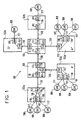
- FIG. 1 is a block diagram of a communication network packet base.
- a packet-based communication network 100 includes a plurality of nodes having terminal or switching nodes 102 and intermediate nodes 105. As is well known in the in a packet-based communication network, packets are transmitted over a virtual connection from a source node 102a to a node recipient 102b, generally traversing one or more nodes 105.
- the source node 102a and the destination node 102b are switching nodes 102 which interface with the local hardware client 108 (CPE).
- the local client hardware 108 may comprise a local network, voice material, image and video equipment, or other types of transmission of data and packets that provide data under form of packets for transmission through the network of packet-based communication to a destination node.
- the local client hardware 108 is interconnected to a node of switching 102 via an access module 110 (AM).
- the module access 110 interfaces with the local client hardware 108 and executes the following functions: packet segmentation and reassembly, admission and bandwidth application, rate control, turnaround of congestion, generation of alarms for congestion situations, and generation of accounting files and statistics.
- the node of switch 102 also includes a transit module 112 (TM) which performs the following functions: multiplexing packets, routing, signaling, congestion management, measurement and reporting the exploitation of resources.
- TM transit module 112
- An interconnection network 115 interconnects all the modules to level of a node. All nodal components can support full duplex communication. For example, an access module can simultaneously switch packets from an access line 117 to the network interconnection 115, and vice versa.
- Intermediate nodes 105 comprise a plurality of modules of transit 112 interconnected by an interconnection network 115.
- Each of the transit modules 112 in an intermediate node 105 provides the interface with a network pivot or junction line 120 and executes all functions identified for transit modules in the nodes of switching 102.
- the transit modules 112 in the intermediate nodes 105 provide for the interconnection of trunk lines 120 through via the interconnection networks 115 of the nodes 105.
- Each virtual connection establishes a communication link between one of the source nodes 102a of the network and a destination node 102b of the corresponding network, via the intermediate nodes 105.
- a virtual connection is the connection between source node A and the destination node D via intermediate nodes B and C.
- another virtual connection shown in Figure 1 is the virtual connection between the source node A 'and the destination node D' through the nodes intermediaries B and C.
- a switching node may be a source node in a virtual connection and a destination node in another connection Virtual.
- a virtual connection can be established between a source node A "and the destination node A 'through the nodes intermediates C and B.
- data generated by local client hardware 108 are provided through access lines 117 to an access module 110 within a source node 102a.
- Data can be formatted in the appropriate packet format by the local client hardware 108 or, alternatively, the access module 110 may have an assembler / disassembler of packages to format correctly the data provided by the local client hardware 108 in order to provide them to the communication network 100.
- Figure 2 is a block diagram of a content access module in a source node or destination node of the communication network of Figure 1.
- the local client hardware 108 provides data to the access modules 110 on access lines 117. At least one dedicated virtual connection is established for each local client hardware 108 connected to the access module 110. Each virtual connection has a queue 205 (constituted by a FIFO), in which the packets provided by the hardware local client 108 are initially stored, and a server 210, which controls the provision of the packets from the queue to the transit module 112. If the information or data provided by local client hardware 108 is not in a correct packet format in order to be provided to the network of communication, an assembler / disassembler of packets can be provided to format the data provided by the local client hardware 108 into the appropriate package format.
- a queue 205 constituted by a FIFO
- the different queues and the different servers associated with each of the virtual connections can be implemented by a unit central processing unit (CPU) which includes processing and appropriate memory to perform the functions described above and by next to the access module 110.
- CPU central processing unit
- the data from the server 210 is applied to a module of transfer. It is also possible to provide a demultiplexer at the exit of the server 110 if the access module 110 is connected to different transit modules 112.
- the access module 110 of the source node 102a also comprises for the opposite direction of transmission, a queue 215 (also performed as FIFO) receiving data from the module of transfer located upstream.
- a queue 215 also performed as FIFO
- a multiplexer is placed at the input of the queue 215.
- the data from this queue 215 are applied to a server 220 comprising means 230 ensuring extraction of information, called Channel Operating Factor (CUF), transmitted in the data stream for local client hardware 108.
- CEF Channel Operating Factor
- CUF information is provided to means 225 including flow rate adjustment in the server 210 so that the data rate transmitted to the hardware client (FIG.1) is adjusted according to the CUF information, the access modules 110 whose function is to control the rate of introduction of packets in the network individually for each virtual connection, as it will be seen later.
- the information CUF is therefore information transmitted in the sense the opposite of the data to which this information applies.
- a CUF going towards a module 110 managing a local client hardware 108 has an effect for the throughput of data transmitted between the access module 110 of this local hardware 108 and the client hardware 108 recipient.
- Figure 3 is a block diagram of a transit module 112 contained in a node of the communication network 100 of FIG.
- each transit module 112 is arranged for full duplex communication between the interconnection network 115 and a trunk line 120.
- a multiplexer 305 performs a multiplexing of the received packets, these packets from access modules 110 (via interconnection networks 115) or other transit modules 112 (through the trunk lines 120).
- the multiplexed packets are applied to servers 310 each comprising means 315 for computing CUF information, the calculated CUF information being inserted into packets transmitted in the other direction of transmission. These insertions are made by referenced insertion means 320.
- outgoing server packets are applied to 325 queues followed demultiplexers 330.
- the demultiplexings are performed according to the addresses of the recipients of the packets (access module 110 or module of transit 112), these addresses being written in the packets.
- the server 310 associated with the forward direction of the virtual connection measures the operating factor CUF channels, which is a measure of the exploitation of critical resources, eg bandwidth, processing power, etc., when packet transmission in a forward direction of the virtual connection.
- a CUF information is for example a byte representing a percentage increase or decrease in flow rate.
- This operating information is written in packages flowing in the return direction (towards the source node) of the connection virtual server 310 associated with the return direction of the virtual path.
- the destination node In the absence of return traffic, the destination node generates an empty packet special feature to provide the operating information to the source node.
- CUF information contained in the packet traffic back from a virtual connection are updates during the transmission so that when the traffic from return reaches the source node, the CUF information contained in the traffic of return indicate the maximum level of exploitation indicated by one any of the resources within the virtual connection. Information Expected CUFs are thus provided to the source node in the most appropriate and effective as possible.
- CUF information associated with resource exploitation by a packet moving in the forward direction do not move with this packet over the entire path to the destination node. Instead of this, the current CUF information associated with a particular node is directly in packets flowing in the direction back to the source node.
- the first node (access node) encountered by the packets moving in the forward direction is usually the critical node and potentially the most limiting (in relation to the exploitation of resources) encountered by the packets in the virtual connection.
- CUF information related to the first node in the forward direction so are the most information relevant provided to the source node during packet transmission by the source node on the virtual connection.
- the source node instructs the server to virtual connection 210 included in the corresponding access module to increase its rate of introduction of packets into the network. However, if CUF information indicates that the resources on the virtual connection are overexploited, the source node orders the virtual connection server 210 to reduce its rate of introduction of packets into the network.
- the period of time between two flow adjustments consecutive is selected to allow the first adjustment of take effect throughout the network before the second adjustment occurs.
- This duration is selected to be equal to at least one round trip time (RTD) on the network.
- RTD round trip time
- a time to go back and forth on the network indicates the time required for a packet transmitted from the source node reaches the destination node and returns to the source node, by via the virtual connection.
- a typical RTD is about 80 to 100 milliseconds
- a typical RTD is approximately 200 to 250 milliseconds.
- each virtual connection has a queue standby 205 and server 210, the packet introduction rate by the server 210 being updated according to the return of the information of the network.
- the rate of introduction of packets into the network by a server 210 for a given virtual connection is called information flow introduced (SIR).
- SIR flow is updated as often as possible, but not in a period of time less than the round trip time RTD on the network, except in cases of major congestion.
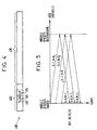
- each packet 400 presents a header portion 402 and a data portion 405.
- the header portion 402 contains different network information required such as routing, signaling, parity checking or error, and several others information known to those skilled in the art.
- the part data 405 contains the data (information) to be transmitted from the node source 102a to the destination node 102b.
- each packet header portion 402 contains a send tag (S) 410 and a tag (R) 411.
- S send tag
- R tag
- a group of packets introduced into the network may present as a burst of packets, or the group can be a long packet flow.
- the access module 110 of the source node updates the SIR, it changes the value of the send tag 410, and sets the new value of the sending tag 410 in the header 402 of all the packets 400 within the group transmitted in the forward direction.
- the server 210 records the time at which the first packet packet group was passed on the virtual connection. Time can stored in a memory register of the server 210, for example.
- the server 210 in the access module 110 of the destination node reads the tag 410 of all received 400 packets for a virtual connection determined and place in the receiving tag of all the packets transmitted in the return direction.
- the access module 110 of the source node waits until it detects that the receiving beacon 411 of the packets received from the network for the determined virtual connection is equal to the sending tag 410 packets corresponding to the time recorded in the memory register. AT this moment, the module is certain that at least one round trip period has passed since the last update of the SIR.
- the RTD is measured in as long as the time difference between the start of the transmission of the group, that is, the time recorded in the memory register, and the time of the receiving the first return packet in the group.
- the access module 110 of the source node detects that the beacon receiving 411 received is equal to the send tag 410 stored within the module, a time going back and forth is detected and a round trip time is determined as the time difference between the moment of transmission and the moment when the return packet is received by the module.
- the measured RTD reflects the current network load (or time) on along the determined virtual connection. Therefore, the updates of the SIRs occur more frequently under low network load conditions high. High frequency of SIR updates speeds up frequency end-to-end processing capacity increases for all Active virtual connections. Under network load conditions high, SIR updates occur less frequently, thus allowing to the flow adjustments to propagate and take full effect in the entire network. This feature is useful for virtual connections that transmit bursty traffic. Bursting traffic creates a charge of high network and short duration when placed on the virtual connection, and bursting traffic is likely to be transferred offline a short time after. Less frequent SIR updates in this case allow the network to immediately transfer much of the burst of traffic via the virtual connection before the SIR of the connection virtual is suddenly increased.
- the access module 110 of the node source of a virtual connection adjusts the SIR according to the CUF received from network.
- the SIR is always greater than or equal to an information rate (CIR), and less than or equal to an excess information rate (EIR).
- the CIR can be determined on the basis of the subscription of the user. For example, a user can subscribe to an IRC of 64 Kbps, or multiples thereof, for example up to 10 Mbps.
- the EIR may depend on the type of access line employed. For example, in the case of a T1 access line, EIR is 1.536 Mbit / s.
- CUF is the key factor in the traffic management system. It's the ratio between the demand for network resources and the totality of available resources. CUF is measured over a period of time, designated by the term congestion monitoring period (CMP). The CMP is long enough to allow accurate statistical measurement CUF, while being short enough to allow several measurements of CUF by RTD. Monitored network resources are the power of processor and the junction bandwidth. The CUF value reported by each node corresponds to the processor exploitation and the exploitation of maximum junction.
- each transit module accumulates the number total of proposed packets (input and output) for a processor determined and the total number of bytes proposed (output only) for a determined junction.
- CPU exploitation is calculated as the ratio of the total number of packages proposed to the maximum switching capacity of the processor.
- Junction operation is calculated as the ratio between the total number of bytes proposed and the maximum bandwidth capacity of the junction. Since CUF is a between the proposed load and the available capacity, the CUF can be greater than 1.
- the CUF is coded and placed in a field of CUF 415 of the packet header 402.
- the CUF field 415 can, by for example, represent values between 1% and 1000%.
- a virtual connection is established between the node source A and the destination node D via intermediate nodes B and C.
- all transit modules 112 along the virtual connection measure the operation processor and junction operation.
- each transit module inserts its measured CUF into all the packets circulating nodes D to A only if the measured CUF is greater than the CUF stored in the packet. Therefore, packets that reach node A contain the maximum CUF encountered along the path in the forward direction of the virtual connection.
- the access module 110 of the source node exploits these information to adjust the SIR setting of the virtual connection in result.
- the operating information is transmitted directly to the source node, thus allowing the operating information to reach the source node quickly, the maximum time being equal to the halfway back and forth on the network (RTD / 2).
- the occupation of each queue is constantly monitored and compared to a set of queue thresholds or congestion levels.
- a transit module can monitor 9 levels of congestion, level 0 corresponding to a "absence of congestion" and the level 8 corresponding to a "congestion
- the intermediate congestion levels are communicated to the access modules 110 of the source node through the mechanism of CUF previously described. This has the effect that the access modules reduce their SIR appropriately to avoid congestion. If Higher congestion levels occur, the transit module affected is likely to use a special CUF option to force all virtual connections involved in reducing their SIR parameter to the parameter CIR.
- the CUF information transmitted to the access module also takes into account the size of the queue and the time of transmission of this information flow management means so as to prevent the overflow of the buffer, when said multiplexed packet rate becomes less than a given threshold value. This is intended to remedy the problem next: if the bit rate transmitted over the virtual connections increases brutally, the number of multiplexed packets (305, FIG.2) increases very quickly too. This can result in an overflow queues 325 downstream of the multiplexers 305, which translates by a packet loss.
- the traffic management method according to the invention applied to a virtual connection of a packet-based communication network where the packets from different local hardware clients are multiplexed before to be temporarily stored in a queue, guarantees a no-loss packets transmitted over the overflow virtual connection of this queue Wait.
- the invention proposes to avoid the overflow of queues 325 by ensuring that channel operating factors (CUFs) in particular the size of these queues, when the multiplexed packets becomes less than a threshold value.
- CEFs channel operating factors
- k TM corresponds to an overload factor related to the size of the queue 325.
- the duration RTD + CMP corresponds to the time elapsing between a measuring the flow on the junction 120 and the moment when this flow is reduced.
- NLR i number of packages * size of a package
- the MTFU load must be brought to a desired TTL value corresponding to a percentage (for example 80%) of TR.
- the CUF information returned is such that an increase in throughput is allowed within the limit of The server 210 (FIG. 2) will then be able to increase its transmission rate.
- the CUF information returned is that a decrease in bit rate is required within the limit of The server 210 (FIG. 2) will then reduce its transmission rate.
- the factor ⁇ of the relation 1 makes it possible to take into account the delay convergence of the emission functions and the reaction time of the system. Simulations have shown that a value of ⁇ equal to 2 appropriate.
- the channel operating factor is usually inserted into packets transmitted towards the recipient client hardware 108 to be intercepted at the server 220 included in the access module 110 of this destination client 108.
- the absence of packets intended for this client operating channels is transmitted in a special empty package in the direction receiving client hardware 108.
- the method of the invention applies in particular to relay networks frame and ATM networks.
Landscapes
- Engineering & Computer Science (AREA)
- Computer Networks & Wireless Communication (AREA)
- Signal Processing (AREA)
- Data Exchanges In Wide-Area Networks (AREA)
Claims (5)
- Verfahren zur Verkehrssteuerung für eine virtuelle Verbindung eines paketvermittelten Kommunikationsnetzes, wobei dieses Verfahren darin besteht:dadurch gekennzeichnet, dass es zur Bestimmung der genannten Überlastinformation darin besteht, eine als Kanalauslastungsfaktor (CUF) bezeichnete Zahl zu bestimmen, und zwar in Abhängigkeit vom Verhältnis zwischen einem Ressourcenbedarf und der Gesamtheit der Ressourcen, die für die virtuelle Verbindung verfügbar sind, sowie außerdem in Abhängigkeit von der Größe der Warteschlange (325) und der Übertragungsdauer dieser Information an die Datenrate-Regelungsvorrichtungen (210);Pakete ausgehend von Quell-Teilnehmerendgeräten (108) zu Ziel-Teilnehmerendgeräten (108) zu übertragen;die von verschiedenen Quell-Teilnehmerendgeräten (108) stammenden Pakete einem Zeitmultiplexverfahren zu unterziehen;die Datenrate der gemultiplexten Pakete zu messen;diese gemultiplexten Pakete vorübergehend in einer Warteschleife (325) zu speichern;diese gespeicherten Pakete über die genannte virtuelle Verbindung (210) zu übertragen;eine Überlastinformation auf dieser virtuellen Verbindung (210) in Richtung der Ziel-Teilnehmerendgeräte (108) zu bestimmen;diese Überlastinformation an Datenrate-Regelungsvorrichtungen (210) zu übertragen und durch diese Datenrate-Regelungsvorrichtungen die Datenrate der Informationen zu regeln, die vor dem Multiplexen eingespeist wurden, um ein Überlaufen der Warteschlange zu verhindern;
und dadurch, dass es zur Regelung der Datenrate- durch diese Datenrate-Regelungsvorrichtungen für die vor dem Multiplexen eingespeisten Informationen darin besteht, die Datenrate in Abhängigkeit von diesem Kanalauslastungsfaktor (CUF) anzupassen. - Verfahren nach Anspruch 1, dadurch gekennzeichnet, dass der Kanalauslastungsfaktor (CUF) eine Information ist, welche die Verifizierung der folgenden Beziehung garantiert:mit SIRi,t gleich der Paketeinspeisungsrate in das Netz für eine virtuelle Verbindung i zum Zeitpunkt t, TR gleich der Paketübertragungsrate auf der virtuellen Verbindung in Richtung der Ziel-Teilnehmereinrichtungen (108), und kTM gleich:

- Verfahren nach Anspruch 2, dadurch gekennzeichnet, dass λ gleich 2 ist.
- Verfahren nach einem der Ansprüche 1 bis 3, dadurch gekennzeichnet, dass der Kanalauslastungsfaktor (CUF) in Pakete eingefügt wird, die in Richtung der Ziel-Teilnehmerendgeräte (108) übertragen werden.
- Verfahren nach einem der Ansprüche 1 bis 3, dadurch gekennzeichnet, dass der Kanalauslastungsfaktor (CUF) in einem speziellen leeren Paket in Richtung der Ziel-Teilnehmerendgeräte (108) übertragen wird, wenn kein Verkehr in RückRichtung vorhanden ist.
Applications Claiming Priority (2)
| Application Number | Priority Date | Filing Date | Title |
|---|---|---|---|
| FR9611940A FR2754123B1 (fr) | 1996-10-01 | 1996-10-01 | Systeme de gestion de trafic et de controle d'encombrement pour reseaux a base de paquets |
| FR9611940 | 1996-10-01 |
Publications (2)
| Publication Number | Publication Date |
|---|---|
| EP0835010A1 EP0835010A1 (de) | 1998-04-08 |
| EP0835010B1 true EP0835010B1 (de) | 2005-02-02 |
Family
ID=9496228
Family Applications (1)
| Application Number | Title | Priority Date | Filing Date |
|---|---|---|---|
| EP97402266A Expired - Lifetime EP0835010B1 (de) | 1996-10-01 | 1997-09-29 | System zur Verkehrssteuerung und Überlastregelung für Paketnetzwerke |
Country Status (6)
| Country | Link |
|---|---|
| US (1) | US7054269B1 (de) |
| EP (1) | EP0835010B1 (de) |
| AT (1) | ATE288647T1 (de) |
| CA (1) | CA2215486A1 (de) |
| DE (1) | DE69732398T2 (de) |
| FR (1) | FR2754123B1 (de) |
Families Citing this family (31)
| Publication number | Priority date | Publication date | Assignee | Title |
|---|---|---|---|---|
| AUPQ274199A0 (en) * | 1999-09-09 | 1999-09-30 | Ericsson Australia Pty Ltd | Information transmission rate control across a core network |
| JP2002271400A (ja) * | 2001-03-09 | 2002-09-20 | Matsushita Electric Ind Co Ltd | データ伝送方法 |
| US6918060B2 (en) * | 2001-10-31 | 2005-07-12 | Intel Corporation | Bounding data transmission latency based upon link loading and arrangement |
| US7313091B2 (en) * | 2002-05-24 | 2007-12-25 | Interdigital Technology Corporation | Method and system for control of congestion in CDMA systems |
| US7236461B1 (en) * | 2002-10-08 | 2007-06-26 | Cisco Technology, Inc. | Link efficiency schemes for packet transport |
| US7221685B2 (en) * | 2002-12-13 | 2007-05-22 | Sbc Properties, L.P. | Method and system relating to bandwidth utilization |
| CA2581729C (en) * | 2006-12-29 | 2016-06-07 | Bce Inc. | Method and system of assigning access connections |
| US7822889B2 (en) * | 2007-08-27 | 2010-10-26 | International Business Machines Corporation | Direct/indirect transmission of information using a multi-tiered full-graph interconnect architecture |
| US7958182B2 (en) | 2007-08-27 | 2011-06-07 | International Business Machines Corporation | Providing full hardware support of collective operations in a multi-tiered full-graph interconnect architecture |
| US8185896B2 (en) | 2007-08-27 | 2012-05-22 | International Business Machines Corporation | Method for data processing using a multi-tiered full-graph interconnect architecture |
| US8108545B2 (en) | 2007-08-27 | 2012-01-31 | International Business Machines Corporation | Packet coalescing in virtual channels of a data processing system in a multi-tiered full-graph interconnect architecture |
| US8014387B2 (en) * | 2007-08-27 | 2011-09-06 | International Business Machines Corporation | Providing a fully non-blocking switch in a supernode of a multi-tiered full-graph interconnect architecture |
| US8140731B2 (en) | 2007-08-27 | 2012-03-20 | International Business Machines Corporation | System for data processing using a multi-tiered full-graph interconnect architecture |
| US7958183B2 (en) | 2007-08-27 | 2011-06-07 | International Business Machines Corporation | Performing collective operations using software setup and partial software execution at leaf nodes in a multi-tiered full-graph interconnect architecture |
| US7769892B2 (en) | 2007-08-27 | 2010-08-03 | International Business Machines Corporation | System and method for handling indirect routing of information between supernodes of a multi-tiered full-graph interconnect architecture |
| US7809970B2 (en) * | 2007-08-27 | 2010-10-05 | International Business Machines Corporation | System and method for providing a high-speed message passing interface for barrier operations in a multi-tiered full-graph interconnect architecture |
| US7904590B2 (en) | 2007-08-27 | 2011-03-08 | International Business Machines Corporation | Routing information through a data processing system implementing a multi-tiered full-graph interconnect architecture |
| US7769891B2 (en) * | 2007-08-27 | 2010-08-03 | International Business Machines Corporation | System and method for providing multiple redundant direct routes between supernodes of a multi-tiered full-graph interconnect architecture |
| US7840703B2 (en) * | 2007-08-27 | 2010-11-23 | International Business Machines Corporation | System and method for dynamically supporting indirect routing within a multi-tiered full-graph interconnect architecture |
| US7793158B2 (en) * | 2007-08-27 | 2010-09-07 | International Business Machines Corporation | Providing reliability of communication between supernodes of a multi-tiered full-graph interconnect architecture |
| US7827428B2 (en) | 2007-08-31 | 2010-11-02 | International Business Machines Corporation | System for providing a cluster-wide system clock in a multi-tiered full-graph interconnect architecture |
| US7921316B2 (en) | 2007-09-11 | 2011-04-05 | International Business Machines Corporation | Cluster-wide system clock in a multi-tiered full-graph interconnect architecture |
| US20090198956A1 (en) * | 2008-02-01 | 2009-08-06 | Arimilli Lakshminarayana B | System and Method for Data Processing Using a Low-Cost Two-Tier Full-Graph Interconnect Architecture |
| US7779148B2 (en) | 2008-02-01 | 2010-08-17 | International Business Machines Corporation | Dynamic routing based on information of not responded active source requests quantity received in broadcast heartbeat signal and stored in local data structure for other processor chips |
| US8077602B2 (en) * | 2008-02-01 | 2011-12-13 | International Business Machines Corporation | Performing dynamic request routing based on broadcast queue depths |
| US8208395B2 (en) | 2008-10-31 | 2012-06-26 | Verizon Patent And Licensing Inc. | System and method for measuring interface utilization using policers |
| US8417778B2 (en) * | 2009-12-17 | 2013-04-09 | International Business Machines Corporation | Collective acceleration unit tree flow control and retransmit |
| US20120236715A1 (en) * | 2011-03-17 | 2012-09-20 | D & S Consultants, Inc. | Measurement Based Admission Control Using Explicit Congestion Notification In A Partitioned Network |
| US8953443B2 (en) | 2011-06-01 | 2015-02-10 | At&T Intellectual Property I, L.P. | Method and apparatus for providing congestion management for a wireless communication network |
| US9166925B2 (en) * | 2013-04-05 | 2015-10-20 | International Business Machines Corporation | Virtual quantized congestion notification |
| US9667807B2 (en) * | 2015-06-03 | 2017-05-30 | Facebook, Inc. | Techniques for dynamic zero-rated server clusters |
Family Cites Families (4)
| Publication number | Priority date | Publication date | Assignee | Title |
|---|---|---|---|---|
| JP2753294B2 (ja) * | 1988-12-23 | 1998-05-18 | 株式会社日立製作所 | パケット輻輳制御方法およびパケット交換装置 |
| EP0487235B1 (de) * | 1990-11-21 | 1999-02-03 | AT&T Corp. | Bandbreitenverwaltung und Überlastabwehr für den Zugang zu Breitband-ISDN-Netzen |
| EP0712220A1 (de) * | 1994-11-08 | 1996-05-15 | International Business Machines Corporation | Knotenpunktsweise Verkehrskontrolle in einem ATM-Netz |
| ZA959722B (en) * | 1994-12-19 | 1996-05-31 | Alcatel Nv | Traffic management and congestion control for packet-based networks |
-
1996
- 1996-10-01 FR FR9611940A patent/FR2754123B1/fr not_active Expired - Fee Related
-
1997
- 1997-09-29 AT AT97402266T patent/ATE288647T1/de not_active IP Right Cessation
- 1997-09-29 DE DE69732398T patent/DE69732398T2/de not_active Expired - Lifetime
- 1997-09-29 EP EP97402266A patent/EP0835010B1/de not_active Expired - Lifetime
- 1997-09-30 CA CA002215486A patent/CA2215486A1/fr not_active Abandoned
- 1997-09-30 US US08/941,236 patent/US7054269B1/en not_active Expired - Fee Related
Also Published As
| Publication number | Publication date |
|---|---|
| DE69732398T2 (de) | 2006-03-30 |
| FR2754123B1 (fr) | 1999-01-08 |
| DE69732398D1 (de) | 2005-03-10 |
| US7054269B1 (en) | 2006-05-30 |
| ATE288647T1 (de) | 2005-02-15 |
| FR2754123A1 (fr) | 1998-04-03 |
| CA2215486A1 (fr) | 1998-04-01 |
| EP0835010A1 (de) | 1998-04-08 |
Similar Documents
| Publication | Publication Date | Title |
|---|---|---|
| EP0835010B1 (de) | System zur Verkehrssteuerung und Überlastregelung für Paketnetzwerke | |
| EP0707399B1 (de) | Verfahren und Vorrichtung zur Überlastregelung in einem Paketkommunikationsnetz | |
| EP0431438B1 (de) | Verfahren zur Regelung des Datenstroms in einem Breitband ISDN und Netz zur Realisierung | |
| US6338046B1 (en) | System and method for determining charges for usage of a network connection | |
| US6208619B1 (en) | Packet data flow control method and device | |
| EP1155531B1 (de) | System und verfahren zur messung der übertragungsdauer und der verluste in einem hochleistungs-telekommunikationsnetz | |
| US6477168B1 (en) | Cell/frame scheduling method and communications cell/frame scheduler | |
| EP0912018B1 (de) | Verfahren zur Flusssteurung in einer ATM-Vermittlungsstelle mit verteilter Architektur | |
| FR2801455A1 (fr) | Procede de transmission de flux de donnees sur un reseau atm, et dispositif pour la mise en oeuvre du procede | |
| FR2682243A1 (fr) | Procede d'allocation de ressources par reservation anticipee dans un reseau satellite a integration de services. | |
| FR2659513A1 (fr) | Installation terminale d'abonne pour reseau asynchrone. | |
| EP0771132B1 (de) | Anlage zur Regulierung des ATM-Zellenflusses in einer ATM-Vermittlungsstelle | |
| JP2002543740A (ja) | Atmネットワークのトラフィックを管理する方法および装置 | |
| FR2775546A1 (fr) | Commutateur de mode de transfert asynchrone avec une fonction d'attribution de file d'attente ayant un debit d'emission proche d'un debit declare | |
| US7414976B2 (en) | Method and apparatus to implement operation and maintenance (OAM) functions on a network processor | |
| JPH1075254A (ja) | セルレート監視装置 | |
| EP3989494B1 (de) | Verfahren zur aggregation und steuerung von nachrichten über einen eingeschränkten bidirektionalen kommunikationskanal | |
| EP0885508B1 (de) | Verfahren zur positionierung von atm-zellen und anlage zu dessen durchführung | |
| EP1090529B1 (de) | Verfahren und vorrichtung zur rückschleifverbindung unter verwendung von ubr mit priorität und einem adsl-modem | |
| EP0959582A1 (de) | Verfahren und Architektur um den Verkehr auf einem digitalen Kommunicationskanal zu kontrollieren | |
| FR2776875A1 (fr) | Procede et dispositif pour optimiser un controle de debit maxi-mini equitable au cours de sessions de communication utilisant un debit binaire disponible | |
| US20040213249A1 (en) | Cell multiplexer for variable speed network interfaces | |
| EP0809382A1 (de) | Verfahren zur Verknüpfung von Knoten eines echtzeitparallelen Rechners | |
| Rogers et al. | Matching differentiated services PHBs to ATM service categories-the AF to VBR case | |
| Kajiyama et al. | Experiments of IP over ATM with congestion avoidance flow control: CEFLAR |
Legal Events
| Date | Code | Title | Description |
|---|---|---|---|
| PUAI | Public reference made under article 153(3) epc to a published international application that has entered the european phase |
Free format text: ORIGINAL CODE: 0009012 |
|
| AK | Designated contracting states |
Kind code of ref document: A1 Designated state(s): AT BE CH DE ES GB IT LI SE |
|
| 17P | Request for examination filed |
Effective date: 19980822 |
|
| AKX | Designation fees paid |
Free format text: AT BE CH DE ES GB IT LI SE |
|
| RBV | Designated contracting states (corrected) |
Designated state(s): AT BE CH DE ES GB IT LI SE |
|
| RAP3 | Party data changed (applicant data changed or rights of an application transferred) |
Owner name: ALCATEL |
|
| RAP3 | Party data changed (applicant data changed or rights of an application transferred) |
Owner name: ALCATEL |
|
| 17Q | First examination report despatched |
Effective date: 20031201 |
|
| GRAP | Despatch of communication of intention to grant a patent |
Free format text: ORIGINAL CODE: EPIDOSNIGR1 |
|
| GRAS | Grant fee paid |
Free format text: ORIGINAL CODE: EPIDOSNIGR3 |
|
| GRAA | (expected) grant |
Free format text: ORIGINAL CODE: 0009210 |
|
| AK | Designated contracting states |
Kind code of ref document: B1 Designated state(s): AT BE CH DE ES GB IT LI SE |
|
| PG25 | Lapsed in a contracting state [announced via postgrant information from national office to epo] |
Ref country code: AT Free format text: LAPSE BECAUSE OF FAILURE TO SUBMIT A TRANSLATION OF THE DESCRIPTION OR TO PAY THE FEE WITHIN THE PRESCRIBED TIME-LIMIT Effective date: 20050202 |
|
| REG | Reference to a national code |
Ref country code: GB Ref legal event code: FG4D Free format text: NOT ENGLISH |
|
| REG | Reference to a national code |
Ref country code: CH Ref legal event code: EP |
|
| REF | Corresponds to: |
Ref document number: 69732398 Country of ref document: DE Date of ref document: 20050310 Kind code of ref document: P |
|
| GBT | Gb: translation of ep patent filed (gb section 77(6)(a)/1977) |
Effective date: 20050311 |
|
| PG25 | Lapsed in a contracting state [announced via postgrant information from national office to epo] |
Ref country code: SE Free format text: LAPSE BECAUSE OF FAILURE TO SUBMIT A TRANSLATION OF THE DESCRIPTION OR TO PAY THE FEE WITHIN THE PRESCRIBED TIME-LIMIT Effective date: 20050502 |
|
| PG25 | Lapsed in a contracting state [announced via postgrant information from national office to epo] |
Ref country code: ES Free format text: LAPSE BECAUSE OF FAILURE TO SUBMIT A TRANSLATION OF THE DESCRIPTION OR TO PAY THE FEE WITHIN THE PRESCRIBED TIME-LIMIT Effective date: 20050513 |
|
| PLBE | No opposition filed within time limit |
Free format text: ORIGINAL CODE: 0009261 |
|
| STAA | Information on the status of an ep patent application or granted ep patent |
Free format text: STATUS: NO OPPOSITION FILED WITHIN TIME LIMIT |
|
| 26N | No opposition filed |
Effective date: 20051103 |
|
| PGFP | Annual fee paid to national office [announced via postgrant information from national office to epo] |
Ref country code: CH Payment date: 20070914 Year of fee payment: 11 |
|
| PGFP | Annual fee paid to national office [announced via postgrant information from national office to epo] |
Ref country code: BE Payment date: 20071004 Year of fee payment: 11 |
|
| BERE | Be: lapsed |
Owner name: ALCATEL Effective date: 20080930 |
|
| REG | Reference to a national code |
Ref country code: CH Ref legal event code: PL |
|
| PG25 | Lapsed in a contracting state [announced via postgrant information from national office to epo] |
Ref country code: BE Free format text: LAPSE BECAUSE OF NON-PAYMENT OF DUE FEES Effective date: 20080930 |
|
| PG25 | Lapsed in a contracting state [announced via postgrant information from national office to epo] |
Ref country code: LI Free format text: LAPSE BECAUSE OF NON-PAYMENT OF DUE FEES Effective date: 20080930 Ref country code: CH Free format text: LAPSE BECAUSE OF NON-PAYMENT OF DUE FEES Effective date: 20080930 |
|
| PGFP | Annual fee paid to national office [announced via postgrant information from national office to epo] |
Ref country code: IT Payment date: 20100927 Year of fee payment: 14 |
|
| PG25 | Lapsed in a contracting state [announced via postgrant information from national office to epo] |
Ref country code: IT Free format text: LAPSE BECAUSE OF NON-PAYMENT OF DUE FEES Effective date: 20110929 |
|
| PGFP | Annual fee paid to national office [announced via postgrant information from national office to epo] |
Ref country code: DE Payment date: 20140922 Year of fee payment: 18 |
|
| PGFP | Annual fee paid to national office [announced via postgrant information from national office to epo] |
Ref country code: GB Payment date: 20140919 Year of fee payment: 18 |
|
| REG | Reference to a national code |
Ref country code: DE Ref legal event code: R119 Ref document number: 69732398 Country of ref document: DE |
|
| GBPC | Gb: european patent ceased through non-payment of renewal fee |
Effective date: 20150929 |
|
| PG25 | Lapsed in a contracting state [announced via postgrant information from national office to epo] |
Ref country code: GB Free format text: LAPSE BECAUSE OF NON-PAYMENT OF DUE FEES Effective date: 20150929 Ref country code: DE Free format text: LAPSE BECAUSE OF NON-PAYMENT OF DUE FEES Effective date: 20160401 |