EP0835012A2 - Circuit de mappage de signaux "DQPSK" - Google Patents
Circuit de mappage de signaux "DQPSK" Download PDFInfo
- Publication number
- EP0835012A2 EP0835012A2 EP97307779A EP97307779A EP0835012A2 EP 0835012 A2 EP0835012 A2 EP 0835012A2 EP 97307779 A EP97307779 A EP 97307779A EP 97307779 A EP97307779 A EP 97307779A EP 0835012 A2 EP0835012 A2 EP 0835012A2
- Authority
- EP
- European Patent Office
- Prior art keywords
- data
- decoding
- nth
- symbol period
- parallel
- Prior art date
- Legal status (The legal status is an assumption and is not a legal conclusion. Google has not performed a legal analysis and makes no representation as to the accuracy of the status listed.)
- Withdrawn
Links
Images


Classifications
-
- H—ELECTRICITY
- H04—ELECTRIC COMMUNICATION TECHNIQUE
- H04L—TRANSMISSION OF DIGITAL INFORMATION, e.g. TELEGRAPHIC COMMUNICATION
- H04L27/00—Modulated-carrier systems
- H04L27/18—Phase-modulated carrier systems, i.e. using phase-shift keying
-
- H—ELECTRICITY
- H04—ELECTRIC COMMUNICATION TECHNIQUE
- H04L—TRANSMISSION OF DIGITAL INFORMATION, e.g. TELEGRAPHIC COMMUNICATION
- H04L27/00—Modulated-carrier systems
- H04L27/18—Phase-modulated carrier systems, i.e. using phase-shift keying
- H04L27/20—Modulator circuits; Transmitter circuits
- H04L27/2032—Modulator circuits; Transmitter circuits for discrete phase modulation, e.g. in which the phase of the carrier is modulated in a nominally instantaneous manner
- H04L27/2053—Modulator circuits; Transmitter circuits for discrete phase modulation, e.g. in which the phase of the carrier is modulated in a nominally instantaneous manner using more than one carrier, e.g. carriers with different phases
- H04L27/206—Modulator circuits; Transmitter circuits for discrete phase modulation, e.g. in which the phase of the carrier is modulated in a nominally instantaneous manner using more than one carrier, e.g. carriers with different phases using a pair of orthogonal carriers, e.g. quadrature carriers
- H04L27/2067—Modulator circuits; Transmitter circuits for discrete phase modulation, e.g. in which the phase of the carrier is modulated in a nominally instantaneous manner using more than one carrier, e.g. carriers with different phases using a pair of orthogonal carriers, e.g. quadrature carriers with more than two phase states
- H04L27/2071—Modulator circuits; Transmitter circuits for discrete phase modulation, e.g. in which the phase of the carrier is modulated in a nominally instantaneous manner using more than one carrier, e.g. carriers with different phases using a pair of orthogonal carriers, e.g. quadrature carriers with more than two phase states in which the data are represented by the carrier phase, e.g. systems with differential coding
Definitions
- This invention relates to a DQPSK mapping circuit for generating DQPSK signals from input data.
- a DQPSK mapping circuit for generating DQPSK signals from input data is known.
- Japanese patent application provisional publication No. 6-252961 discloses a ⁇ /4 shift QPSK mapping circuit.
- Japanese utility model application provisional publication No. 5-78050 discloses a ⁇ /4 DQPSK encoder.
- the aim of the present invention is to provide an improved DQPSK mapping circuit.
- a DQPSK mapping circuit which comprises: a parallel decoding circuit having inputs for decoding first to 2Nth bits of input data and one symbol period prior I and Q data which are prior by one symbol period from the present decoding cycle thereof through the inputs and outputting serial first to Nth I and Q data of the present decoding cycle in parallel, N is a natural number; and a supplying circuit for supplying the Nth I and Q data to the inputs as the one symbol period prior I and Q data in the succeeding decoding cycle of the parallel decoding circuit.
- the parallel decoding circuit may comprise first to Nth decoders, an Mth decoder out of the first to Nth decoders decoding 2Mth bit and (2M-1)th bits of the input data and outputs of (M-1)th decoder, M being a natural number and M ⁇ N, wherein the first decoder decodes one symbol period prior I and Q data and the first and second bits of the input data.
- the supplying circuit may comprise a holding circuit, that is, a flip-flop circuit, for holding values of the Nth I and Q data of the present decoding cycle and outputting the values in the succeeding decoding cycle.
- a DQPSK mapping circuit which comprises: a first flip-flop circuit for holding and outputting values of input data of first to 2Nth bits in response to a clock signal indicative of one symbol period; a parallel decoding circuit having inputs for decoding input data of first to 2Nth bits and one symbol period prior I and Q data which are prior by the one symbol period from the present decoding cycle through the inputs and outputting serial first to Nth I and Q data of the present decoding cycle in parallel, N being a natural number; and a second flip-flop circuit responsive to the clock signal for holding values of the Nth I and Q data in the present decoding cycle and outputting the values in the succeeding decoding cycle.
- the DQPSK mapping circuit of the second aspect may further comprise a first selecting circuit responsive to a second clock signal for outputting one of the serial first to Nth I data of the present decoding period successively and a second selecting circuit responsive to the second clock signal for outputting one of the serial first to Nth symbol period Q data of the present decoding period successively, a frequency of the second clock signal being 1/N of a frequency of the first clock signal.
- the parallel decoding circuit comprises first to Nth decoders, an Mth decoder out of the first to Nth decoders decoding 2Mth bit and (2M-1)th bits of the input data and outputs of (M-1)th decoder, M being a natural number and M ⁇ N, wherein the first decoder decodes the one symbol period prior I and Q data and the first and second bits of the input data.
- Fig. 1 is a block diagram of a DQPSK (Differential quadrature phase-shift keying) mapping circuit of the embodiment to the present invention.
- DQPSK Different quadrature phase-shift keying
- Numerals 19 to 26 denote flip-flop circuits for holding values of the input symbols (Xn, Yn), (Xn+1, Yn+1), (Xn+2, Yn+2), and (Xn+3, Yn+3) at the same time in response to a clock signal CLK1 31.
- Numerals 29 and 30 denote two bits of orthogonal signals (In-1, Qn-1) 27 and 28 which are prior by two symbol periods.
- the clock signal 31 is supplied to inputs of the flip-flop circuit 19 to 26 and 29 and 30.
- Numeral 32 denotes a parallel decoder for obtaining the present symbol orthogonal signals (In, Qn), (In+1, Qn+1), (In+2, Qn+2), (In+3, Qn+3) at the same time from the eight bits of input symbol data from the flip-flop circuit 19 to 26 and the orthogonal signal data which is prior by one symbol period from the flip-flop circuit 29 and 30.
- Numerals 33 and 34 denotes selectors for controlling the outputs signals of the parallel decoder 32.
- Numeral 35 denotes a controller responsive to a clock signal 36 for controlling the selectors 33 and 34 in response to the clock signal CLK2 36.
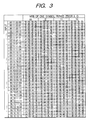
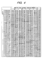
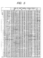
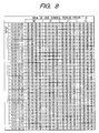
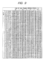
- Figs. 2 to 9 are tables of signal conditions of this embodiment.
- Fig. 10 is a graphical drawing showing signal point location of this embodiment.
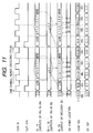
- Fig. 11 is a time chart of this embodiment.
- Figs. 2 to 9 show signal point locations after transient when eight bits of input symbols (Xn, Yn), (Xn+1, Yn+1), (Xn+2, Yn+2), and (Xn+3, Yn+3) are inputted.
- the input symbols are (LSB) 0 1 0 0 0 1 1 1 (MSB) Xn Yn Xn+1 Yn+1 Xn+2 Yn+2 Xn+3 Yn+3 (LSB) 0 1 1 0 1 0 0 1 (MSB) Xn+4 Yn+4 Xn+5 Yn+5 Xn+6 Yn+6 Xn+7 Yn+7 and the signal point location is assumed as 1 ⁇ in an initial condition. The operation in this condition will be described referring to Fig. 11.
- the four symbols of decoded data are successively outputted from LSB (present symbol outputs 38, 42 at the I channel signals 46 and 47 as serial outputs. That is, the signal point locations changes in the order of 1 ⁇ ⁇ 2 ⁇ ⁇ 2 ⁇ ⁇ 3 ⁇ ⁇ 1 ⁇ .
- the data of four symbols are successively output serially from LSB at the Ich and Qch outputs 46 and 47 by the selectors 33 and 34 in response to the output 37 of the controller 37 generated in response to the clock signal CLK2 36. That is, the signal point locations changes in the order of 2 ⁇ ⁇ 1 ⁇ ⁇ 4 ⁇ ⁇ 1 ⁇ .
- the parallel decoder 32 outputs the present symbols (In, Qn, In+1, Qn+1, In+2, Qn+2, In+3, Qn+3) at the same time by decoding one symbol period prior data (In-1, Qn-1) and the input symbols (Xn, Yn, Xn+1, Yn+1, Xn+2, Yn+2, Xn+3, Yn+3) successively.
- the signal point location transients as follows: 1 ⁇ (initial condition) ⁇ 2 ⁇ ⁇ 2 ⁇ ⁇ 3 ⁇ ⁇ 1 ⁇ ⁇ 2 ⁇ ⁇ 1 ⁇ ⁇ 4 ⁇ ⁇ 1 ⁇
- Fig. 12 is a block diagram of the parallel decoder 32 shown in Fig. 1.
- the input symbol (Xn, Yn) and one symbol period prior orthogonal signals (In-1, Qn-1) are inputted to the decoder 50.
- outputs of the decoder 50 are inputted to the decoder 51 as one symbol period prior orthogonal signals (In-1, Qn-1) in the decoder 51 which are decoded with the input symbol (Xn+1, Yn+1).
- outputs of the decoder 51 are inputted to the decoder 52 as one symbol period prior orthogonal signals (In-1, Qn-1) in the decoder 52 which are decoded with the input symbol (Xn+2, Yn+2).
- outputs of the decoder 52 are inputted to the decoder 53 as one symbol period prior orthogonal signals (In-1, Qn-1) in the decoder 53 which are decoded with the input symbol (Xn+3, Yn+3).
- the decoders 50 to 53 outputs the present symbols (In, Qn, In+1, Qn+1, In+2, Qn+2, In+3, Qn+3) in parallel at the same time.
- an Mth decoder out of the first decoder 50 to Nth decoder 53 decodes 2Mth bit and (2M-1)th bits of the input data and outputs of (M-1)th decoder, M being a natural number and M ⁇ N, wherein the first decoder 50 decodes the one symbol period prior I and Q data and the first and second bits of the input data.
Landscapes
- Engineering & Computer Science (AREA)
- Computer Networks & Wireless Communication (AREA)
- Signal Processing (AREA)
- Digital Transmission Methods That Use Modulated Carrier Waves (AREA)
- Compression, Expansion, Code Conversion, And Decoders (AREA)
- Dc Digital Transmission (AREA)
- Synchronisation In Digital Transmission Systems (AREA)
Applications Claiming Priority (3)
| Application Number | Priority Date | Filing Date | Title |
|---|---|---|---|
| JP264917/96 | 1996-10-04 | ||
| JP8264917A JPH10112735A (ja) | 1996-10-04 | 1996-10-04 | Dqpsk変調用マッピング回路 |
| JP26491796 | 1996-10-04 |
Publications (2)
| Publication Number | Publication Date |
|---|---|
| EP0835012A2 true EP0835012A2 (fr) | 1998-04-08 |
| EP0835012A3 EP0835012A3 (fr) | 2001-05-23 |
Family
ID=17410005
Family Applications (1)
| Application Number | Title | Priority Date | Filing Date |
|---|---|---|---|
| EP97307779A Withdrawn EP0835012A3 (fr) | 1996-10-04 | 1997-10-02 | Circuit de mappage de signaux "DQPSK" |
Country Status (5)
| Country | Link |
|---|---|
| US (1) | US6075827A (fr) |
| EP (1) | EP0835012A3 (fr) |
| JP (1) | JPH10112735A (fr) |
| KR (1) | KR100289238B1 (fr) |
| CN (1) | CN1095268C (fr) |
Families Citing this family (5)
| Publication number | Priority date | Publication date | Assignee | Title |
|---|---|---|---|---|
| TW499112U (en) * | 2001-03-02 | 2002-08-11 | Macronix Int Co Ltd | Tangent angle calculating device and DQPSK demodulator using the same |
| US7248646B1 (en) | 2002-04-19 | 2007-07-24 | Analog Devices Inc. | Digital reconfigurable core for multi-mode base-band transmitter |
| US7228154B2 (en) * | 2004-11-03 | 2007-06-05 | Sony Corporation | Method and system for processing wireless digital multimedia |
| CN101218767B (zh) * | 2005-07-08 | 2011-02-09 | 富士通株式会社 | 光学dqpsk接收器的相位监测装置、相位控制装置及其方法 |
| US7933354B2 (en) * | 2006-11-22 | 2011-04-26 | Semtech Corporation | Encoding and decoding architecture and method for pipelining encoded data or pipelining with a look-ahead strategy |
Family Cites Families (8)
| Publication number | Priority date | Publication date | Assignee | Title |
|---|---|---|---|---|
| US4714913A (en) * | 1985-07-16 | 1987-12-22 | Cohen Robert K | Quadrature phase signal processor |
| US5157693A (en) * | 1991-04-01 | 1992-10-20 | Motorola, Inc. | Digital modulation circuit |
| JPH0578050A (ja) * | 1991-09-18 | 1993-03-30 | Mitsubishi Electric Corp | エレベータの案内装置 |
| JPH0583307A (ja) * | 1991-09-24 | 1993-04-02 | Kenwood Corp | π/4DQPSKエンコーダ |
| US5369378A (en) * | 1992-02-13 | 1994-11-29 | Sanyo Electric Co., Ltd. | Digital DQPSK modulator |
| US5717394A (en) * | 1993-02-10 | 1998-02-10 | Ricoh Company Ltd. | Method and apparatus for encoding and decoding data |
| JP2901169B2 (ja) * | 1993-02-23 | 1999-06-07 | 日本電信電話株式会社 | π/4シフトQPSK変調用マッピング回路 |
| JPH06315039A (ja) * | 1993-04-30 | 1994-11-08 | Toshiba Corp | π/4シフトDQPSK変調器 |
-
1996
- 1996-10-04 JP JP8264917A patent/JPH10112735A/ja active Pending
-
1997
- 1997-09-30 CN CN97119372A patent/CN1095268C/zh not_active Expired - Fee Related
- 1997-10-02 EP EP97307779A patent/EP0835012A3/fr not_active Withdrawn
- 1997-10-04 KR KR1019970051136A patent/KR100289238B1/ko not_active Expired - Fee Related
- 1997-10-06 US US08/944,510 patent/US6075827A/en not_active Expired - Fee Related
Also Published As
| Publication number | Publication date |
|---|---|
| CN1095268C (zh) | 2002-11-27 |
| EP0835012A3 (fr) | 2001-05-23 |
| KR100289238B1 (ko) | 2001-05-02 |
| JPH10112735A (ja) | 1998-04-28 |
| US6075827A (en) | 2000-06-13 |
| KR19980032563A (ko) | 1998-07-25 |
| CN1182320A (zh) | 1998-05-20 |
Similar Documents
| Publication | Publication Date | Title |
|---|---|---|
| US5913229A (en) | Buffer memory controller storing and extracting data of varying bit lengths | |
| EP0835012A2 (fr) | Circuit de mappage de signaux "DQPSK" | |
| WO2002039585A3 (fr) | Selecteur d'horloge multiphase a large bande passante a sortie de phase continue | |
| JPH08181679A (ja) | 疑似乱数雑音発生装置 | |
| EP1223716A2 (fr) | Générateur de forme d'onde | |
| JP2004343768A (ja) | 整数でない長さを有するタイミングの再生ループ | |
| CA2349854A1 (fr) | Circuit d'addition d'erreurs fictives | |
| US5881109A (en) | Pulse shaping filter for π/4-shift QPSK modulator | |
| EP0821492A2 (fr) | Circuit générateur de code de correction d'erreur et modulateur utilisant ce circuit | |
| EP1821195A1 (fr) | Dispositif de decalage en barillet | |
| RU2232474C2 (ru) | Способ и устройство синхронизации и устранения фазовой неоднозначности сигналов систем связи | |
| KR20010091164A (ko) | 의사잡음 코드 발생 장치 | |
| JPH09325882A (ja) | 一様乱数発生回路 | |
| JP2901169B2 (ja) | π/4シフトQPSK変調用マッピング回路 | |
| KR960003290A (ko) | 영상 수신 시스템의 비트 동기 보정회로 | |
| JP2577986B2 (ja) | 擬似ランダム雑音符号発生器 | |
| KR100336290B1 (ko) | 비트 동기가 혼합된 고속 디인터리빙 장치 및 방법 | |
| KR100434364B1 (ko) | 직렬 가산기 | |
| JPH04258025A (ja) | 可変長符号復号回路 | |
| JP2005130283A (ja) | マッチトフィルタ回路および相関演算方法 | |
| JPH02170726A (ja) | ビタビ復号回路 | |
| JPH06188931A (ja) | ディジタル変調器のベースバンド信号生成回路 | |
| KR100241749B1 (ko) | 데이터 전송장치 | |
| KR200341732Y1 (ko) | 가변 코드율 비터비 디코더의 입력심볼율 변환장치 | |
| US20030086484A1 (en) | Receiver and inverse-spreading code generating method |
Legal Events
| Date | Code | Title | Description |
|---|---|---|---|
| PUAI | Public reference made under article 153(3) epc to a published international application that has entered the european phase |
Free format text: ORIGINAL CODE: 0009012 |
|
| 17P | Request for examination filed |
Effective date: 19971011 |
|
| AK | Designated contracting states |
Kind code of ref document: A2 Designated state(s): DE FR GB |
|
| AX | Request for extension of the european patent |
Free format text: AL;LT;LV;RO;SI |
|
| PUAL | Search report despatched |
Free format text: ORIGINAL CODE: 0009013 |
|
| AK | Designated contracting states |
Kind code of ref document: A3 Designated state(s): AT BE CH DE DK ES FI FR GB GR IE IT LI LU MC NL PT SE |
|
| AX | Request for extension of the european patent |
Free format text: AL;LT;LV;RO;SI |
|
| RIC1 | Information provided on ipc code assigned before grant |
Free format text: 7H 04L 27/22 A, 7H 04L 27/20 B |
|
| AKX | Designation fees paid |
Free format text: DE FR GB |
|
| 17Q | First examination report despatched |
Effective date: 20050428 |
|
| STAA | Information on the status of an ep patent application or granted ep patent |
Free format text: STATUS: THE APPLICATION IS DEEMED TO BE WITHDRAWN |
|
| 18D | Application deemed to be withdrawn |
Effective date: 20060530 |