EP0835014A2 - Subscriber circuit for connecting an analog subscriber line to a digital time multiplex telephone exchange - Google Patents
Subscriber circuit for connecting an analog subscriber line to a digital time multiplex telephone exchange Download PDFInfo
- Publication number
- EP0835014A2 EP0835014A2 EP97114283A EP97114283A EP0835014A2 EP 0835014 A2 EP0835014 A2 EP 0835014A2 EP 97114283 A EP97114283 A EP 97114283A EP 97114283 A EP97114283 A EP 97114283A EP 0835014 A2 EP0835014 A2 EP 0835014A2
- Authority
- EP
- European Patent Office
- Prior art keywords
- subscriber line
- circuit
- test
- subscriber
- slic2
- Prior art date
- Legal status (The legal status is an assumption and is not a legal conclusion. Google has not performed a legal analysis and makes no representation as to the accuracy of the status listed.)
- Ceased
Links
Images
Classifications
-
- H—ELECTRICITY
- H04—ELECTRIC COMMUNICATION TECHNIQUE
- H04M—TELEPHONIC COMMUNICATION
- H04M3/00—Automatic or semi-automatic exchanges
- H04M3/005—Interface circuits for subscriber lines
-
- H—ELECTRICITY
- H04—ELECTRIC COMMUNICATION TECHNIQUE
- H04Q—SELECTING
- H04Q2213/00—Indexing scheme relating to selecting arrangements in general and for multiplex systems
- H04Q2213/13003—Constructional details of switching devices
-
- H—ELECTRICITY
- H04—ELECTRIC COMMUNICATION TECHNIQUE
- H04Q—SELECTING
- H04Q2213/00—Indexing scheme relating to selecting arrangements in general and for multiplex systems
- H04Q2213/1309—Apparatus individually associated with a subscriber line, line circuits
-
- H—ELECTRICITY
- H04—ELECTRIC COMMUNICATION TECHNIQUE
- H04Q—SELECTING
- H04Q2213/00—Indexing scheme relating to selecting arrangements in general and for multiplex systems
- H04Q2213/1316—Service observation, testing
Definitions
- the invention relates to a subscriber line circuit for the connection of an analog subscriber line to a digital one Time-division multiplex telephone exchange.
- one of the functions implemented by means of relays the test access of a test device to the subscriber line circuit and on the wires of the subscriber line.
- the object of the invention is to reduce the effort for To reduce the implementation of the relay functions mentioned.
- a subscriber line circuit serves to solve this problem with the features specified in claim 1.
- the features of the invention only their interface part SLIC2, the multifunctional relay circuit provided according to the invention MR and a test circuit TS indicated.
- the Interface part SLIC2 is in practice in a high-voltage part and divided into a low voltage / signal processor part.
- the functions of the feed are essentially in the high-voltage section the subscriber line with programmable food characteristics in the idle state and conversation as well as the detection of the current on wires a and b of the subscriber line.
- Essential tasks of the low-voltage / signal processor module are the programmable definition of relative transmit and receive levels, the implementation of a programmable Input impedance, the implementation of the 2/4 wire implementation with programmable after-image impedance as well as coding / decoding of the speech signals.
- Interface part SLIC2 in addition to the functions mentioned Test functions implemented in addition to a self-test of Subscriber circuit the checking of the subscriber line for open circuit or earth faults in the cable wires as well as a review of the to the subscriber line connected subscriber terminal concern.
- the multifunctional relay provided according to the invention MR has two changeover contacts u1 and u2, with the help of which the a-wire and the b-wire of the subscriber line from the Inputs a1 and b1 from the interface part SLIC2 of the subscriber line circuit separated and instead these inputs a1 and a2 can be connected to a test circuit TS.
- test circuit TS can consist of a single one Resistance through which in the case of connection the inputs a1 and b1 of the interface part SLIC2 of the Participant circuit are interconnected.
- the multifunctional relay circuit serves on the one hand in context with the functions Precut over and Power Cross the subscriber line circuit or its part SLIC2 from disconnect the wires of the subscriber line.
- SLIC2 Precut over and Power Cross the subscriber line circuit or its part SLIC2 from disconnect the wires of the subscriber line.
- the fact that in this connection with the disconnection the test circuit TS to the inputs a1 and b1 of the subscriber line circuit is irrelevant.
- Integrated test functions are initially implemented a self-test by actuating the multifunctional relay MR the wires of the subscriber line from inputs a1 and b1 disconnected and the test circuit connected to these inputs, the simplest case of their embodiment in the aforementioned only a connection of the inputs a1 and b1 through a resistor.
- Self-tests can make the test circuit more complex Have structure, namely with a passive network represent complex resistance behavior.
- the test circuit TS To carry out the actual the subscriber line and the tests relating to the subscriber terminal are in the other Switch position of the multifunctional relay circuit MR the wires a and b of the subscriber line back to the inputs a1 and a2 switched on, the test circuit TS, however, is disconnected at this stage of the test and out of service.
- test circuit When executing the connection area of a digital telephone exchange, where the subscriber line circuits are grouped together, the test circuit instead of individual lines, only individual groups be available, in which case an internal test bus is present on which the group-specific test circuit and with which the line-specific multifunctional Relay circuits make a connection.
Landscapes
- Engineering & Computer Science (AREA)
- Signal Processing (AREA)
- Monitoring And Testing Of Exchanges (AREA)
- Interface Circuits In Exchanges (AREA)
Abstract
Sie besteht unter anderem aus einer Schnittstellenschaltung
(SLIC2) mit integrierten die Teilnehmerleitung (TL) betreffenden
Prüffunktionen, einer im einfachsten Fall durch einen
ohmschen Widerstand realisierten Testschaltung (TS) und einer
zwei Umschaltekontakte (u1, u2) aufweisende Relaisschaltung
(MR), durch die in der einen Schaltstellung die Adern (a, b)
der Teilnehmerleitung mit der Schnittstellenschaltung verbunden
werden und in der anderen Schaltstellung die Teilnehmerleitung
abgetrennt und die Testschaltung an die Schnittstellenschaltung
angeschaltet wird.
Description
Die Erfindung betrifft eine Teilnehmeranschlußschaltung für den Anschluß einer analogen Teilnehmerleitung an eine digitale Zeitmultiplex-Fernsprechvermittlungsstelle.The invention relates to a subscriber line circuit for the connection of an analog subscriber line to a digital one Time-division multiplex telephone exchange.
Trotz des Trends bei Teilnehmeranschlußschaltungen moderner
digitaler Zeitmultiplex-Fernsprechvermittlungsstellen zu möglichst
vollständigen Halbleiterlösungen und zur Integration
der Bauelemente verbleiben Funktionen, die bisher aus technologischen
und aus Kostengründen nach wie vor unter Verwendung
von Relais realisiert werden. Hierzu gehören Abschaltfunktionen,
bei denen die Adern der Teilnehmerleitung von der Teilnehmeranschlußschaltung
abgetrennt werden. Eine solche Abtrennung
kommt beim Leistungsmerkmal ![]()
![]()
Ferner gehört zu den mittels Relais realisierten Funktionen der Testzugriff eines Prüfgeräts auf die Teilnehmeranschlußschaltung und auf die Adern der Teilnehmerleitung.Furthermore, one of the functions implemented by means of relays the test access of a test device to the subscriber line circuit and on the wires of the subscriber line.
Bei bisherigen Lösungen werden für die erwähnten Relaisfunktionen drei gesonderte Relais eingesetzt, nämlich eines für die Realisierung der Abtrennung der Adern der Teilnehmerleitung bei den Funktionen Precut over und Power Cross und zwei Relais im Zusammenhang mit dem Testzugriff, von denen das eine der Anschaltung des Prüfgeräts an die Teilnehmeranschlußschaltung unter Abtrennung der Teilnehmerleitung von den Eingängen der Teilnehmeranschlußschaltung dient, so daß eine Überprüfung des Betriebs der Teilnehmeranschlußschaltung vorgenommen werden kann und das andere der Anschaltung des Prüfgeräts an die Teilnehmerleitung, ebenfalls unter Abtrennung der Teilnehmerleitung von der Teilnehmeranschlußschaltung dient, um eine Überprüfung der Teilnehmerleitung vornehmen zu können.In previous solutions for the relay functions mentioned three separate relays used, namely one for the realization of the separation of the wires of the subscriber line with the functions Precut over and Power Cross and two Relay related test access, one of which the connection of the test device to the subscriber line circuit separating the subscriber line from the entrances the subscriber line circuit is used so that a Check the operation of the subscriber line circuit made and the other is the connection of the test device to the subscriber line, also under separation the subscriber line from the subscriber line circuit serves to make a review of the subscriber line can.
Die Aufgabe der Erfindung besteht darin, den Aufwand für die Realisierung der erwähnten Relaisfunktionen zu verringern.The object of the invention is to reduce the effort for To reduce the implementation of the relay functions mentioned.
Der Lösung dieser Aufgabe dient eine Teilnehmeranschlußschaltung mit den im Patentanspruch 1 angegebenen Merkmalen.A subscriber line circuit serves to solve this problem with the features specified in claim 1.
Bei der erfindungsgemäßen Teilnehmerschaltung wird für die genannte Relaisfunktion lediglich ein einziges Umschalterelais benötigt, das somit sozusagen ein multifunktionales Relais ist. Ermöglicht wird dies aufgrund des Umstandes, daß die Teilnehmerschaltung so ausgestaltet ist, daß sie selbst Prüffunktionen durchführen kann. Als Folge hiervon genügt als Testschaltung, die erfindungsgemäß im Zusammenhang mit der Durchführung von Prüfungen mittels des Relais an die Teilnehmeranschlußschaltung angeschaltet wird, im einfachsten Fall ein Widerstand.In the subscriber circuit according to the invention Relay function mentioned only a single changeover relay needed, which is a multifunctional relay is. This is made possible due to the fact that the subscriber circuit is designed so that it itself Can perform test functions. As a result, it suffices as Test circuit, the invention in connection with the Carrying out tests using the relay on the subscriber line circuit is switched on, in the simplest case a resistance.
Nachstehend wird die Erfindung anhand eines Ausführungsbeispiels unter Bezugnahme auf eine Figur näher erläutert.The invention based on an exemplary embodiment explained in more detail with reference to a figure.
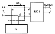
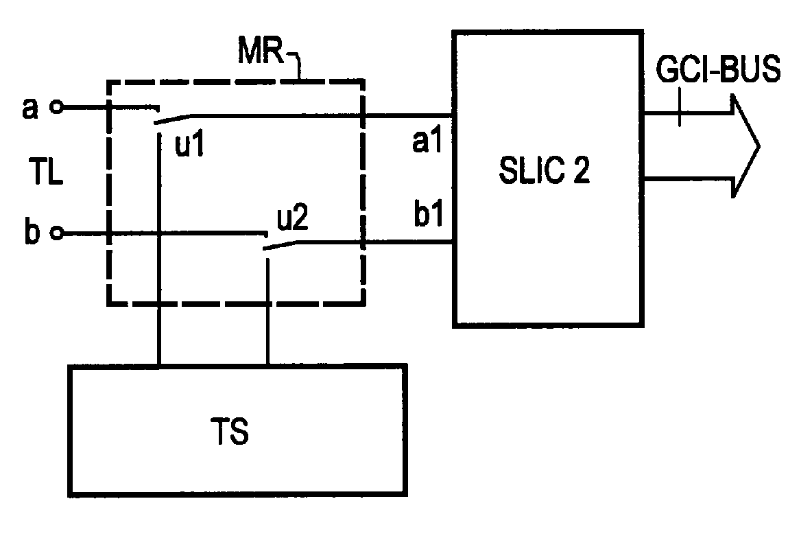
In der Figur sind von einer Teilnehmeranschlußschaltung mit den erfindungsgemäßen Merkmalen nur deren Schnittstellenteil SLIC2, die erfindungsgemäß vorgesehene multifunktionale Relaisschaltung MR sowie eine Testschaltung TS angedeutet. Der Schnittstellenteil SLIC2 ist in der Praxis in einen Hochvoltteil und in einen Niedervolt/Signalprozessorteil gegliedert. Im Hochvoltteil sind im wesentlichen die Funktionen der Speisung der Teilnehmerleitung mit programmierbarer Speisecharakteristik im Ruhe- und Gesprächszustand sowie die Detektierung des Stromes auf den Adern a und b der Teilnehmerleitung realisiert. Wesentliche Aufgaben des Niedervolt/Signalprozessorbausteins sind die programmierbare Festlegung relativer Sende- und Empfangs-Pegel, die Realisierung einer programmierbaren Eingangsimpedanz, die Durchführung der 2/4-Draht-Umsetzung mit programmierbarer Nachbildimpedanz sowie die Codierung/Decodierung der Sprachsignale.In the figure are from a subscriber line circuit the features of the invention only their interface part SLIC2, the multifunctional relay circuit provided according to the invention MR and a test circuit TS indicated. Of the Interface part SLIC2 is in practice in a high-voltage part and divided into a low voltage / signal processor part. The functions of the feed are essentially in the high-voltage section the subscriber line with programmable food characteristics in the idle state and conversation as well as the detection of the current on wires a and b of the subscriber line. Essential tasks of the low-voltage / signal processor module are the programmable definition of relative transmit and receive levels, the implementation of a programmable Input impedance, the implementation of the 2/4 wire implementation with programmable after-image impedance as well as coding / decoding of the speech signals.
Bei der erfindungsgemäßen Teilnehmeranschlußschaltung sind im Schnittstellenteil SLIC2 außer den genannten Funktionen auch Prüffunktionen realisiert, die neben einem Eigentest der Teilnehmeranschlußschaltung die Überprüfung der Teilnehmerleitung auf Leitungsunterbrechung oder Erdschlüsse der Leitungsadern sowie eine Überprüfung des an die Teilnehmerleitung angeschlossenen Teilnehmerendgerätes betreffen.In the subscriber line circuit according to the invention Interface part SLIC2 in addition to the functions mentioned Test functions implemented in addition to a self-test of Subscriber circuit the checking of the subscriber line for open circuit or earth faults in the cable wires as well as a review of the to the subscriber line connected subscriber terminal concern.
Das gemäß der Erfindung vorgesehene multifunktionale Relais MR weist zwei Umschaltekontakte u1 und u2 auf, mit deren Hilfe die a-Ader und die b-Ader der Teilnehmerleitung von den Eingängen a1 und b1 vom Schnittstellenteil SLIC2 der Teilnehmeranschlußschaltung abgetrennt und stattdessen diese Eingänge a1 und a2 mit einer Testschaltung TS verbunden werden können.The multifunctional relay provided according to the invention MR has two changeover contacts u1 and u2, with the help of which the a-wire and the b-wire of the subscriber line from the Inputs a1 and b1 from the interface part SLIC2 of the subscriber line circuit separated and instead these inputs a1 and a2 can be connected to a test circuit TS.
Im einfachsten Fall kann die Testschaltung TS aus einem einzigen Widerstand bestehen, durch den im Falle der Anschaltung die Eingänge a1 und b1 des Schnittstellenteils SLIC2 der Teilnehmerschaltung miteinander verbunden sind.In the simplest case, the test circuit TS can consist of a single one Resistance through which in the case of connection the inputs a1 and b1 of the interface part SLIC2 of the Participant circuit are interconnected.
Die multifunktionale Relaisschaltung dient einerseits im Zusammenhang mit den Funktionen Precut over und Power Cross dazu, die Teilnehmeranschlußschaltung bzw. deren Teil SLIC2 von den Adern der Teilnehmerleitung abzutrennen. Der Umstand, daß in diesem Zusammenhang mit der Abtrennung die Testschaltung TS an die Eingänge a1 und b1 der Teilnehmeranschlußschaltung gelegt wird, ist dabei ohne Belang.The multifunctional relay circuit serves on the one hand in context with the functions Precut over and Power Cross the subscriber line circuit or its part SLIC2 from disconnect the wires of the subscriber line. The fact that in this connection with the disconnection the test circuit TS to the inputs a1 and b1 of the subscriber line circuit is irrelevant.
Im Zusammenhang mit der Durchführung von Prüfungen durch die im Schnittstellenteil SLIC2 der Teilnehmeranschlußschaltung integrierten Prüffunktionen werden zunächst zur Durchführung einer Eigenprüfung durch Betätigung des multifunktionalen Relais MR die Adern der Teilnehmerleitung von den Eingängen a1 und b1 abgetrennt und die Testschaltung an diese Eingänge angeschaltet, die im vorgenannten einfachsten Fall ihrer Ausführungsform lediglich eine Verbindung der Eingänge a1 und b1 über einen Widerstand bewirkt. Für die Durchführung komplexerer Eigenprüfungen kann die Testschaltung auch einen aufwendigeren Aufbau aufweisen, nämlich ein passives Netzwerk mit komplexem Widerstandsverhalten darstellen.In connection with the execution of tests by the in the interface part SLIC2 of the subscriber line circuit Integrated test functions are initially implemented a self-test by actuating the multifunctional relay MR the wires of the subscriber line from inputs a1 and b1 disconnected and the test circuit connected to these inputs, the simplest case of their embodiment in the aforementioned only a connection of the inputs a1 and b1 through a resistor. For performing more complex Self-tests can make the test circuit more complex Have structure, namely with a passive network represent complex resistance behavior.
Zur Durchführung der eigentlichen die Teilnehmerleitung und das Teilnehmerendgerät betreffenden Prüfungen sind in der anderen Schaltstellung der multifunktionalen Relaisschaltung MR die Adern a und b der Teilnehmerleitung wieder an die Eingänge a1 und a2 angeschaltet, die Testschaltung TS hingegen ist in diesem Stadium der Prüfung abgetrennt und außer Betrieb.To carry out the actual the subscriber line and the tests relating to the subscriber terminal are in the other Switch position of the multifunctional relay circuit MR the wires a and b of the subscriber line back to the inputs a1 and a2 switched on, the test circuit TS, however, is disconnected at this stage of the test and out of service.
Bei Ausführungen des Anschlußbereichs einer digitalen Fernsprechvermittlungsstelle, bei denen die Teilnehmeranschlußschaltungen gruppenweise zusammengefaßt sind, kann die Testschaltung statt leitungsindividuell nur gruppenindividuell vorhanden sein, in welchem Falle ein gruppeninterner Testbus vorhanden ist, an dem die gruppenindividuelle Testschaltung liegt und mit dem die leitungsindividuellen multifunktionalen Relaisschaltungen eine Verbindung herstellen.When executing the connection area of a digital telephone exchange, where the subscriber line circuits are grouped together, the test circuit instead of individual lines, only individual groups be available, in which case an internal test bus is present on which the group-specific test circuit and with which the line-specific multifunctional Relay circuits make a connection.
Claims (2)
Applications Claiming Priority (2)
| Application Number | Priority Date | Filing Date | Title |
|---|---|---|---|
| DE19639885 | 1996-09-27 | ||
| DE19639885A DE19639885C1 (en) | 1996-09-27 | 1996-09-27 | Subscriber connection circuit for connecting an analog subscriber line to a digital time-division multiplex telephone exchange |
Publications (2)
| Publication Number | Publication Date |
|---|---|
| EP0835014A2 true EP0835014A2 (en) | 1998-04-08 |
| EP0835014A3 EP0835014A3 (en) | 2004-01-14 |
Family
ID=7807162
Family Applications (1)
| Application Number | Title | Priority Date | Filing Date |
|---|---|---|---|
| EP97114283A Ceased EP0835014A3 (en) | 1996-09-27 | 1997-08-19 | Subscriber circuit for connecting an analog subscriber line to a digital time multiplex telephone exchange |
Country Status (8)
| Country | Link |
|---|---|
| US (1) | US6052437A (en) |
| EP (1) | EP0835014A3 (en) |
| CN (1) | CN1150743C (en) |
| AR (1) | AR008488A1 (en) |
| BR (1) | BR9704897A (en) |
| DE (1) | DE19639885C1 (en) |
| RU (1) | RU2162278C2 (en) |
| TW (1) | TW357535B (en) |
Cited By (1)
| Publication number | Priority date | Publication date | Assignee | Title |
|---|---|---|---|---|
| US8649528B2 (en) | 2001-02-02 | 2014-02-11 | Techtronic A/S | Microphone unit with internal A/D converter |
Families Citing this family (3)
| Publication number | Priority date | Publication date | Assignee | Title |
|---|---|---|---|---|
| DE19907925C2 (en) * | 1999-02-24 | 2000-12-28 | Siemens Ag | Subscriber connection circuit for connecting an analog subscriber line with integrated means for carrying out test functions |
| IL144158A (en) * | 2001-07-05 | 2011-06-30 | Mosaid Technologies Inc | Outlet for connecting an analog telephone set to a digital data network carrying voice signals in digital form |
| DE102005046964A1 (en) * | 2005-09-30 | 2007-04-05 | Siemens Ag | DC-set test performing method for subscriber line module, involves testing functions of module based on information, which represents current that is to be tested and is determined from information representing current flowing over resistor |
Family Cites Families (19)
| Publication number | Priority date | Publication date | Assignee | Title |
|---|---|---|---|---|
| US3912882A (en) * | 1973-12-07 | 1975-10-14 | Tm Systems | Remote loop-back terminating unit for testing telephone |
| SU720788A1 (en) * | 1975-10-17 | 1980-03-05 | Предприятие П/Я Р-6609 | Device for protecting station equipment in the customer line |
| SU658789A1 (en) * | 1975-12-22 | 1979-04-25 | Предприятие П/Я Р-6609 | Digital signal switching device |
| DE2816408C2 (en) * | 1978-04-15 | 1985-08-01 | Telefonbau Und Normalzeit Gmbh, 6000 Frankfurt | Circuit arrangement for testing the subscriber lines of a digital time-division multiplex telephone exchange |
| SU1158016A1 (en) * | 1980-07-01 | 1988-04-30 | Предприятие П/Я Р-6609 | Device for receiving user's answer signal |
| US4424421A (en) * | 1981-10-23 | 1984-01-03 | Lynch Communication Systems, Inc. | Apparatus for testing subscriber carrier systems |
| FR2518855A1 (en) * | 1981-12-18 | 1983-06-24 | Trt Telecom Radio Electr | Individual line and integrated subscriber junctor test device - has loop state simulator and multiplexer affording different voltages for digital processing |
| US4611320A (en) * | 1984-05-21 | 1986-09-09 | Siemens Corporate Research And Support, Inc. | Programmable testing analyzer |
| AR240603A1 (en) * | 1985-04-30 | 1990-05-31 | Siemens Ag | Arrangement for determining the values of analog voltages occuring on telephone subscriber lines |
| DE3534861C2 (en) * | 1985-09-30 | 1994-04-28 | Siemens Ag | Semiconductor switch consisting of two MOS switching transistors connected in series with their source-drain paths |
| US4807277A (en) * | 1987-05-15 | 1989-02-21 | Keptel, Inc. | Remotely activated switching apparatus |
| GB2229063B (en) * | 1989-03-09 | 1993-04-07 | Plessey Telecomm | Telecommunications exchange apparatus |
| EP0451759B1 (en) * | 1990-04-12 | 1996-11-20 | Siemens Aktiengesellschaft | Method for testing the transmission characteristics of a subscriber line circuit |
| JPH05167679A (en) * | 1991-12-17 | 1993-07-02 | Hitachi Ltd | Switching system and subscriber circuit controller |
| US5323460A (en) * | 1992-01-07 | 1994-06-21 | Ag Communication Systems Corporation | Enhanced subscriber line interface circuit |
| GB9200332D0 (en) * | 1992-01-08 | 1992-02-26 | Plessey Telecomm | Termination unit with maintenance facility |
| US5483573A (en) * | 1993-06-30 | 1996-01-09 | Keptel, Inc. | Electric circuit connector with auto-termination |
| DE4402461A1 (en) * | 1994-01-28 | 1995-08-03 | Sel Alcatel Ag | Protection circuit for a subscriber line circuit and subscriber line circuit with it |
| US5677941A (en) * | 1995-03-02 | 1997-10-14 | Lucent Technologies Inc. | Channel test unit |
-
1996
- 1996-09-27 DE DE19639885A patent/DE19639885C1/en not_active Expired - Fee Related
-
1997
- 1997-08-19 EP EP97114283A patent/EP0835014A3/en not_active Ceased
- 1997-09-18 US US08/933,532 patent/US6052437A/en not_active Expired - Lifetime
- 1997-09-22 TW TW086113732A patent/TW357535B/en not_active IP Right Cessation
- 1997-09-24 RU RU97116044/09A patent/RU2162278C2/en not_active IP Right Cessation
- 1997-09-26 AR ARP970104443A patent/AR008488A1/en unknown
- 1997-09-26 BR BR9704897A patent/BR9704897A/en not_active Application Discontinuation
- 1997-09-26 CN CNB971196303A patent/CN1150743C/en not_active Expired - Fee Related
Cited By (1)
| Publication number | Priority date | Publication date | Assignee | Title |
|---|---|---|---|---|
| US8649528B2 (en) | 2001-02-02 | 2014-02-11 | Techtronic A/S | Microphone unit with internal A/D converter |
Also Published As
| Publication number | Publication date |
|---|---|
| RU2162278C2 (en) | 2001-01-20 |
| BR9704897A (en) | 1998-11-24 |
| US6052437A (en) | 2000-04-18 |
| DE19639885C1 (en) | 1998-03-26 |
| AR008488A1 (en) | 2000-01-19 |
| CN1178423A (en) | 1998-04-08 |
| EP0835014A3 (en) | 2004-01-14 |
| CN1150743C (en) | 2004-05-19 |
| TW357535B (en) | 1999-05-01 |
Similar Documents
| Publication | Publication Date | Title |
|---|---|---|
| EP0835014A2 (en) | Subscriber circuit for connecting an analog subscriber line to a digital time multiplex telephone exchange | |
| EP0242563A2 (en) | Protection circuit for the overvoltage protection of a subscriber circuit | |
| DE10310208A1 (en) | Distributor with test access | |
| EP1203483A1 (en) | Method and device for increasing the fail safety of information desks connected to exchanges | |
| DE3323592C2 (en) | ||
| DE3633562C1 (en) | Change-over switching device for a telephone facility for connecting a number of extensions to a common telephone line | |
| EP0634861B1 (en) | Subscriber line circuit for connecting a subscriber line with a digital time division exchange | |
| DE3832619C1 (en) | Checkable line termination for a telephone line and method for checking the line termination from the telephone switchboard | |
| DE2153623C3 (en) | Process for handling operations in a computer-controlled telephone exchange | |
| DE3434791C2 (en) | ||
| DE881376C (en) | Circuit arrangement for telephone systems, in particular for telecommunications | |
| DE492894C (en) | Circuit arrangement for telephone systems with several exchanges | |
| WO1997001938A1 (en) | Main distribution board for a telecommunications facility | |
| DE2945032C2 (en) | Method for testing the transmission device for dialing information from trunk transmissions | |
| DE765912C (en) | Circuit arrangement for preset mixer selectors in telecommunications systems, especially telephone systems | |
| DE3833745C2 (en) | ||
| DE3832618C1 (en) | Checkable line termination for a telephone line | |
| DE953438C (en) | Circuit arrangement for telephone systems for connecting officers to incoming lines and for monitoring the activities of the officers | |
| AT251053B (en) | System for automating long-distance traffic in telephone service | |
| DD272561A1 (en) | METHOD FOR CHECKING AN ANALOGUE SCHEDULE CONNECTIONS AND ITS END STAGES THROUGH A PCM TRANSMISSION ROUTE CONNECTED TO A DIGITAL INTERCOM TRANSMISSION SYSTEM (II) | |
| DD285916A7 (en) | CIRCUIT ARRANGEMENT FOR THE TESTING OF A REMOTE TRANSMISSION TRANSMISSION ERROR POTENTIAL AND THE CURRENT CAPABILITY OF THE PARTICIPANT DEVICE FOR LARGE SELECTION PLANT FACILITIES | |
| DE4409669A1 (en) | Analogue telephone handset adaptor for integrated services digital network | |
| DE3609061A1 (en) | LOOP CONDITION DETECTOR, ESPECIALLY FOR PROCESSOR CONTROLLED DIGITAL TELEPHONE ACCESS | |
| DE1003813B (en) | Circuit arrangement for relay selectors (couplers) consisting of coupling relays in telecommunication systems, especially telephone systems | |
| DE2440125B2 (en) | CIRCUIT ARRANGEMENT FOR MONITORING THE NUMBER OF TRANSMISSION DEVICES CONNECTED TO CALL CALL LINES |
Legal Events
| Date | Code | Title | Description |
|---|---|---|---|
| PUAI | Public reference made under article 153(3) epc to a published international application that has entered the european phase |
Free format text: ORIGINAL CODE: 0009012 |
|
| AK | Designated contracting states |
Kind code of ref document: A2 Designated state(s): AT BE CH DE DK ES FI FR GB GR IE IT LI LU MC NL PT SE |
|
| AX | Request for extension of the european patent |
Free format text: AL;LT;LV;RO;SI |
|
| PUAL | Search report despatched |
Free format text: ORIGINAL CODE: 0009013 |
|
| AK | Designated contracting states |
Kind code of ref document: A3 Designated state(s): AT BE CH DE DK ES FI FR GB GR IE IT LI LU MC NL PT SE |
|
| AX | Request for extension of the european patent |
Extension state: AL LT LV RO SI |
|
| RIC1 | Information provided on ipc code assigned before grant |
Ipc: 7H 04M 3/30 B Ipc: 7H 04M 3/00 A |
|
| 17P | Request for examination filed |
Effective date: 20040105 |
|
| 17Q | First examination report despatched |
Effective date: 20040226 |
|
| AKX | Designation fees paid |
Designated state(s): AT BE CH DE DK ES FI FR GB GR IE LI |
|
| RBV | Designated contracting states (corrected) |
Designated state(s): AT BE CH DE ES FI FR GB GR IT LI PT |
|
| STAA | Information on the status of an ep patent application or granted ep patent |
Free format text: STATUS: THE APPLICATION HAS BEEN REFUSED |
|
| 18R | Application refused |
Effective date: 20061127 |