EP0835170B1 - Verfahren und vorrichtung zum reibschweissen von werkstücken - Google Patents
Verfahren und vorrichtung zum reibschweissen von werkstücken Download PDFInfo
- Publication number
- EP0835170B1 EP0835170B1 EP96922876A EP96922876A EP0835170B1 EP 0835170 B1 EP0835170 B1 EP 0835170B1 EP 96922876 A EP96922876 A EP 96922876A EP 96922876 A EP96922876 A EP 96922876A EP 0835170 B1 EP0835170 B1 EP 0835170B1
- Authority
- EP
- European Patent Office
- Prior art keywords
- friction
- rotation
- workpieces
- angle
- process according
- Prior art date
- Legal status (The legal status is an assumption and is not a legal conclusion. Google has not performed a legal analysis and makes no representation as to the accuracy of the status listed.)
- Expired - Lifetime
Links
- 238000000034 method Methods 0.000 title claims description 34
- 238000003466 welding Methods 0.000 title claims description 33
- 239000000463 material Substances 0.000 claims description 20
- 238000002844 melting Methods 0.000 claims description 10
- 230000008018 melting Effects 0.000 claims description 10
- 238000005242 forging Methods 0.000 claims 3
- 235000019589 hardness Nutrition 0.000 claims 2
- 229910000831 Steel Inorganic materials 0.000 description 5
- 229910052782 aluminium Inorganic materials 0.000 description 5
- XAGFODPZIPBFFR-UHFFFAOYSA-N aluminium Chemical compound [Al] XAGFODPZIPBFFR-UHFFFAOYSA-N 0.000 description 5
- 238000010586 diagram Methods 0.000 description 5
- 239000010959 steel Substances 0.000 description 5
- 230000006835 compression Effects 0.000 description 4
- 238000007906 compression Methods 0.000 description 4
- 238000005259 measurement Methods 0.000 description 4
- 229910001092 metal group alloy Inorganic materials 0.000 description 4
- 238000004904 shortening Methods 0.000 description 3
- 229910045601 alloy Inorganic materials 0.000 description 2
- 239000000956 alloy Substances 0.000 description 2
- 230000005540 biological transmission Effects 0.000 description 2
- 238000005516 engineering process Methods 0.000 description 2
- 238000012986 modification Methods 0.000 description 2
- 230000004048 modification Effects 0.000 description 2
- 229910000838 Al alloy Inorganic materials 0.000 description 1
- FYYHWMGAXLPEAU-UHFFFAOYSA-N Magnesium Chemical compound [Mg] FYYHWMGAXLPEAU-UHFFFAOYSA-N 0.000 description 1
- 230000015572 biosynthetic process Effects 0.000 description 1
- 238000004364 calculation method Methods 0.000 description 1
- 238000010276 construction Methods 0.000 description 1
- 230000000694 effects Effects 0.000 description 1
- 230000002349 favourable effect Effects 0.000 description 1
- -1 ferrous metals Chemical class 0.000 description 1
- 238000010438 heat treatment Methods 0.000 description 1
- 229910001234 light alloy Inorganic materials 0.000 description 1
- 229910052749 magnesium Inorganic materials 0.000 description 1
- 239000011777 magnesium Substances 0.000 description 1
- 238000004519 manufacturing process Methods 0.000 description 1
- 229910052751 metal Inorganic materials 0.000 description 1
- 239000002184 metal Substances 0.000 description 1
- 238000012544 monitoring process Methods 0.000 description 1
- 239000007787 solid Substances 0.000 description 1
- 238000011144 upstream manufacturing Methods 0.000 description 1
Images

Classifications
-
- B—PERFORMING OPERATIONS; TRANSPORTING
- B23—MACHINE TOOLS; METAL-WORKING NOT OTHERWISE PROVIDED FOR
- B23K—SOLDERING OR UNSOLDERING; WELDING; CLADDING OR PLATING BY SOLDERING OR WELDING; CUTTING BY APPLYING HEAT LOCALLY, e.g. FLAME CUTTING; WORKING BY LASER BEAM
- B23K20/00—Non-electric welding by applying impact or other pressure, with or without the application of heat, e.g. cladding or plating
- B23K20/12—Non-electric welding by applying impact or other pressure, with or without the application of heat, e.g. cladding or plating the heat being generated by friction; Friction welding
- B23K20/121—Control circuits therefor
-
- B—PERFORMING OPERATIONS; TRANSPORTING
- B23—MACHINE TOOLS; METAL-WORKING NOT OTHERWISE PROVIDED FOR
- B23K—SOLDERING OR UNSOLDERING; WELDING; CLADDING OR PLATING BY SOLDERING OR WELDING; CUTTING BY APPLYING HEAT LOCALLY, e.g. FLAME CUTTING; WORKING BY LASER BEAM
- B23K20/00—Non-electric welding by applying impact or other pressure, with or without the application of heat, e.g. cladding or plating
- B23K20/12—Non-electric welding by applying impact or other pressure, with or without the application of heat, e.g. cladding or plating the heat being generated by friction; Friction welding
Definitions
- the invention relates to a method and a device for friction welding workpieces from different Materials or with different Material properties, especially different ones Hardness and / or melting temperature, with the characteristics in the General term of the process and Device main claim.
- Friction welding processes and friction welding devices are in known in practice in different versions.
- the Both workpieces to be welded are e.g. under Frictional contact rotated relative to each other, being on the Friction point are heated and plasticized. After a the intended period of time, the rotary drive is stopped, whereby the relative rotation slows down braking and to Standstill comes. During the run the two Workpieces compressed and connected by an axial stroke. With conventional friction welding processes, this takes Grinding process for several seconds, with speeds of 1000 rpm and more are used. This conventional procedure is the same or in the Properties very similar materials practical and has proven itself. For friction welding of workpieces made of different materials, e.g. B.
- the invention solves this problem with the features in Process and device main claim.
- total angle of rotation during the rubbing process to one limited low value.
- Practical experience gained should be the angle of rotation not be greater than 1080 ° or 3 full revolutions.
- Rotation angles are between 180 ° to 720 °, being optimal Results for a rotation angle range from 290 ° to 430 ° be won.
- the Angle of rotation ranges vary. You definitely lie much lower than with conventional processes.
- the method according to the invention and the associated one Device are suitable for all applications in which the workpieces made of materials exist with significant Differences in material properties, in particular the hardness and / or the melting temperature.
- Such pairings arise from completely different ones Materials such as steel and light metal alloys, e.g. B. Aluminum, magnesium / aluminum etc. Areas of application are also light metal alloys or non-ferrous metals with each other when the materials are in the pairing through different heat treatment, alloy formation etc. in hardness, strength, melting temperature etc. differentiate.
- the melting properties can also be very different for other reasons.
- the preferred area of application is tubular, in particular cylindrical tubular workpieces. But there are Solid / tubular pairings also possible. In attempts have good results for dimensional relationships Outside diameter / wall thickness of the pipes of 10: 1 or larger, preferably 20: 1 or larger.
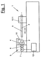
- Figure 1 shows a friction welding device (1) for Connection of two workpieces (2, 3) by friction welding.
- This is a single-head machine in which one workpiece (2) in a lathe chuck trained clamping device (4) and the other Workpiece (3) in an axially movable Tensioning device (8) is tensioned.
- the tensioning device (8) also represents the upsetting device (11) with towards the end of the rubbing process the compression stroke or End stop for the axial connection of the two workpieces (2,3).
- the two workpieces (2, 3) are preferably as cylindrical tubes formed or point to the Weld point on pipe sections. You have a Dimension ratio of outer diameter / wall thickness of at least 10: 1, preferably 20: 1 or greater. Preferred areas of application are shafts or axes in the Vehicle construction. There are also any other Areas of application.
- the two workpieces (2, 3) differ significantly in their workpiece properties, especially their hardness and / or melting temperature.
- the workpiece with the higher one Hardness or melting temperature is preferably in of the tensioning device (4) excited with the Rotary drive (5) is connected.
- the connection of a Articulated head (2) made of steel with an articulated shaft (3) the consists of an aluminum alloy.
- the base material e.g. B. alloys of different hardness, in particular Light metal alloys, that will be harder or higher melting workpiece (2) also on the Rotary drive side cocked.
- the rotary drive (5) consists in a manner known per se a motor (7) and a transmission (6), which with the Chuck (4) are connected.
- the rotary drive (5) is operated via a machine control (12) preferably computerized and freely programmable.
- the friction welding device (1) has in the area of rotating clamping device (4) also a device (10) to plan the friction surface of the harder or higher melting workpiece (2).
- a device (10) to plan the friction surface of the harder or higher melting workpiece (2).
- the two workpieces are (2,3) axially distanced from each other.
- the rotary drive (5) is started and turns up at idle, while at the same time the two workpieces (2, 3) from the upsetting device (11) or the feed device along the axis of rotation (9) in Rapid traverse can be approximated.
- one Aluminum / steel connection it is approx. 300 rpm. It can range from 50 to 500 based on practical experience RPM vary and also outside of this range depending on Material pair lie.
- the angle of rotation of the relative rotation during the rubbing process is limited. It measures itself from the start of rubbing to standstill the rotational movement (rubbing process).
- the start of rubbing is the point in time at which a measurable and significant Workpiece deformation begins and the accompanying Workpiece shortening begins.
- the start of rubbing can be done with preferably slight delay after the first Touch the workpieces (2,3). The delay can on the one hand by metrological reasons and on the other hand by the delivery speed and / or an upstream so-called rubbing time be determined.
- the rubbing time is the time from the start of rubbing to Switch off the rotary drive (5). Turns off after switching off the workpiece (2) by the inertia in Drivetrain still braking up to the frictional forces to the rotation standstill.
- the angle of rotation is in the embodiment shown preferably 290 ° to 430 °. Will be usable results also for a rotation angle range between approx. 180 ° to Get 720 °. Based on previous experience, the Angle of rotation is not higher than 1080 °.
- the angle of rotation is only in the embodiment shown adjusted and controlled via the friction time.
- the inertia in the drive train accordingly matched, so that after the drive is switched off a quick Braking takes place. It is particularly recommended reduce the moving masses and make an appropriate one Gear ratio (6) to choose. This also stands in line with the desired low idle speed of approx. 300 rpm.
- the angle of rotation is measured, which e.g. exact and direct via an angle measurement using an encoder or indirectly and approximated by a continuous speed measurement and a back calculation is done. From measurement technology For this reason, the speed measurement starts shortly after the start of friction and ends shortly before the rotation stops.
- the diagram of Figure 2 illustrates the measuring range.
- the measured or calculated rotation angle can be slightly smaller than be the actual angle of rotation.
- the required friction time can be achieved Attempts to be determined empirically.
- the setting of the Friction time takes place on the machine control (12).
- a The practical value for the friction time is approx. 100 msec a speed of approx. 300 rpm and a rotation angle of about 360 °, the braking phase after switching off is also approximately 100 msec.
- the friction welding device (1) are different Measuring devices (not shown) arranged. So lets For example, the first contact of the workpieces (2, 3) and / or the start of rubbing over that in the upsetting device (11) determine the force or pressure occurring and measure up. Other suitable measuring methods are also alternative and appropriate devices can be used. For example the start of friction can also be determined via the delivery path become.
- the tolerances are the Workpieces (2,3) and the clamping very low, so that the delivery route is a significant size in sufficient Represents accuracy.
- the angle of rotation from the start of friction to Rotation standstill measured or calculated and monitored.
- the speed can also be monitored here, which is preferably clocked and in real time during the Friction time occurs shortly before rotation stops.
- Suitable measuring devices for measuring the Workpiece path and workpiece shortening available. These are also like the others mentioned above Measuring devices with machine control (12) connected.
- the various measuring devices can not only be used for Monitoring of the friction welding process and its parameters, but also to control and regulate the Friction welding process can be used. That's the way it is for example possible, if you want a more precise one Compliance with the angle of rotation a braking device, preferably to use an electric motor brake, which the rotary drive (5) depending on the measured Angle of rotation actively brakes and possibly stops.
- This Braking device can on the side of the rotary drive (5) be arranged and act directly on it. Alternatively, an increased braking effect can also be achieved via a higher friction and the upsetting device (11) achieved become.
Landscapes
- Engineering & Computer Science (AREA)
- Mechanical Engineering (AREA)
- Pressure Welding/Diffusion-Bonding (AREA)
- Lining Or Joining Of Plastics Or The Like (AREA)
Description
- Figur 1 :
- eine Reibschweißvorrichtung in Seitenansicht und
- Figur 2 :
- einen Reibschweißvorgang im Ablaufdiagramm mit den Veränderungen von Drehzahl, Druck und Weg über der Zeit.
- 1
- Reibschweißvorrichtung
- 2
- Werkstück, hart
- 3
- Werkstück, weich
- 4
- Spanneinrichtung
- 5
- Drehantrieb
- 6
- Getriebe
- 7
- Motor
- 8
- Spanneinrichtung
- 9
- Drehachse
- 10
- Planvorrichtung
- 11
- Stauchvorrichtung
- 12
- Steuerung
Claims (15)
- Verfahren zum Reibschweißen von Werkstücken aus unterschiedlichen Werkstoffen oder mit unterschiedlichen Werkstoffeigenschaften, insbesondere unterschiedlicher Härte und/oder Schmelztemperatur, wobei die Werkstücke unter Reibkontakt relativ zueinander gedreht, gestoppt und gestaucht werden, dadurch gekennzeichnet, daß die Werkstücke (2,3) beim Reibvorgang über einen begrenzten Drehwinkel von weniger als 1080° relativ zueinander gedreht werden.
- Verfahren nach Anspruch 1, dadurch gekennzeichnet, daß der Drehwinkel der Relativdrehung ca. 180° bis 720°, vorzugsweise 290° bis 430° beträgt.
- Verfahren nach Anspruch 1 oder 2, dadurch gekennzeichnet, daß der Drehwinkel direkt oder mittelbar gemessen wird.
- Verfahren nach Anspruch 1, 2 oder 3, dadurch gekennzeichnet, daß der Drehwinkel über die Reibzeit und Abschaltung des Drehantriebs (5) gesteuert wird.
- Verfahren nach Anspruch 4, dadurch gekennzeichnet, daß die Reibzeit auf die Massenträgheiten der bewegten Maschinenteile und des bewegten Werkstücks (2) sowie die Reibkräfte abgestimmt ist.
- Verfahren nach einem der Ansprüche 1 bis 5, dadurch gekennzeichnet, daß der Drehantrieb (5) im Leerlauf mit einer begrenzten Drehzahl von ca. 50 bis 500 U/min, vorzugsweise ca. 300 U/min läuft.
- Verfahren nach einem der Ansprüche 1 bis 6, dadurch gekennzeichnet, daß das widerstandsfähigere Werkstück (2) gedreht wird.
- Verfahren nach einem der Ansprüche 1 bis 7, dadurch gekennzeichnet, daß die Reibschweißfläche des gedrehten Werkstücks (2) vor dem Reibschweißen in der Spannstellung senkrecht zur Drehachse (9) geplant wird.
- Verfahren nach einem der Ansprüche 1 bis 8, dadurch gekennzeichnet, daß der Reibbeginn der Werkstücke (2,3) über eine Messung von Druck oder Kraft in der Stauchvorrichtung (11) oder den Zustellweg festgestellt wird.
- Vorrichtung zum Reibschweißen von Werkstücken aus unterschiedlichen Werkstoffen oder mit unterschiedlichen Werkstoffeigenschaften, insbesondere unterschiedlicher Härte und/oder Schmelztemperatur, mit mindestens einem Drehantrieb und einer Stauchvorrichtung, welche die Werkstücke relativ zueinander drehen, stoppen und unter Stauchdruck aneinanderpressen, wobei die Reibschweißvorrichtung eine Einrichtung zum Feststellen des Reibbeginns und eine Steuerung zur Einstellung der Reibzeit oder des Drehwinkels aufweist, dadurch gekennzeichnet, daß die Steuerung (12) derart ausgebildet ist, daß sie Relativdrehungen der Werkstücke (2,3) beim Reibvorgang über einen begrenzten Drehwinkel von weniger als 1080° steuert.
- Vorrichtung nach Anspruch 10, dadurch gekennzeichnet, daß die Steuerung (12) auf abgestimmte kurze Reibzeiten zur Erzielung der gewünschten Drehwinkel einstellbar ist.
- Vorrichtung nach Anspruch 10 oder 11, dadurch gekennzeichnet, daß die Steuerung (12) auf Drehwinkel von ca. 180° bis 720°, vorzugsweise 290° bis 430°, eingestellt ist.
- Vorrichtung nach Anspruch 10, 11 oder 12, dadurch gekennzeichnet, daß die Reibschweißvorrichtung (1) eine Einrichtung zum Messen oder Berechnen des Drehwinkels und/oder der Drehzahl des Werkstücks (2) aufweist.
- Vorrichtung nach einem der Ansprüche 10 bis 13, dadurch gekennzeichnet, daß der Drehantrieb (5) eine Leerlaufdrehzahl von ca. 50 bis 500 U/min, vorzugsweise ca. 300 U/min, aufweist.
- Vorrichtung nach einem der Ansprüche 10 bis 14, dadurch gekennzeichnet, daß die Reibschweißvorrichtung (1) eine Planvorrichtung (10) für das gedrehte Werkstück (2) aufweist.
Applications Claiming Priority (3)
| Application Number | Priority Date | Filing Date | Title |
|---|---|---|---|
| DE19523240A DE19523240C1 (de) | 1995-06-27 | 1995-06-27 | Verfahren und Vorrichtung zum Reibschweißen von Werkstücken |
| DE19523240 | 1995-06-27 | ||
| PCT/EP1996/002702 WO1997001412A1 (de) | 1995-06-27 | 1996-06-21 | Verfahren und vorrichtung zum reibschweissen von werkstücken |
Publications (2)
| Publication Number | Publication Date |
|---|---|
| EP0835170A1 EP0835170A1 (de) | 1998-04-15 |
| EP0835170B1 true EP0835170B1 (de) | 1999-11-24 |
Family
ID=7765310
Family Applications (1)
| Application Number | Title | Priority Date | Filing Date |
|---|---|---|---|
| EP96922876A Expired - Lifetime EP0835170B1 (de) | 1995-06-27 | 1996-06-21 | Verfahren und vorrichtung zum reibschweissen von werkstücken |
Country Status (5)
| Country | Link |
|---|---|
| US (1) | US6021938A (de) |
| EP (1) | EP0835170B1 (de) |
| DE (2) | DE19523240C1 (de) |
| ES (1) | ES2139366T3 (de) |
| WO (1) | WO1997001412A1 (de) |
Families Citing this family (23)
| Publication number | Priority date | Publication date | Assignee | Title |
|---|---|---|---|---|
| DE19711236A1 (de) * | 1997-03-18 | 1998-09-24 | Burkhard Prof Dr Dr Suthoff | Reibschweißartige Fügung von Magnesium mit Stählen und Nichteisenmetallen |
| DE19732076A1 (de) | 1997-07-25 | 1999-01-28 | Porsche Ag | Verfahren zur Herstellung eines Rades für ein Kraftfahrzeug |
| JP3209170B2 (ja) * | 1997-12-02 | 2001-09-17 | 日本軽金属株式会社 | アルミニウム合金製中空部材の摩擦圧接方法及び継手 |
| ATE277716T1 (de) * | 1998-11-02 | 2004-10-15 | Spinduction Weld Inc | Verbessertes schweissverfahen von festkörpern und geschweisste werkstücke |
| DE19930444C5 (de) * | 1999-07-02 | 2005-10-20 | Daimler Chrysler Ag | Stabilisatoranordnung für ein Kraftfahrzeug |
| DE10330188A1 (de) * | 2003-07-03 | 2005-02-03 | Kuka Schweissanlagen Gmbh | Verfahren und Vorrichtung zum Pressschweißen |
| DE10341490A1 (de) * | 2003-09-09 | 2005-03-31 | Abb Patent Gmbh | Verfahren zur Verbindung von Bauteilen untereinander |
| US20050263569A1 (en) * | 2004-05-27 | 2005-12-01 | Miller Michael L | Portable friction welder |
| US20060043155A1 (en) * | 2004-08-24 | 2006-03-02 | Jeff Lovin | Method and system of friction welding |
| DE102004045135B3 (de) * | 2004-09-17 | 2006-04-27 | Veritas Ag | Verfahren und Vorrichtung zum Verbinden von Leitungen, Kraftfahrzeug mit einer derartigen Vorrichtung |
| DE102006016099B4 (de) * | 2006-04-04 | 2010-04-22 | Benteler Stahl/Rohr Gmbh | Verfahren zur Herstellung einer Getriebehohlwelle |
| US8740042B2 (en) * | 2006-07-19 | 2014-06-03 | Nippon Light Metal Company, Ltd. | Friction-welded part and method of friction welding |
| DE202008001457U1 (de) * | 2008-02-01 | 2009-06-10 | S.M.A. Metalltechnik Gmbh & Co. Kg | Rohrleitungssystem, insbesondere eines Kältemittelkreislaufs in einem Kraftfahrzeug |
| GB2482003B (en) * | 2010-07-14 | 2012-08-22 | Rolls Royce Plc | Process control method |
| DE202012103219U1 (de) | 2012-08-24 | 2013-12-02 | Kuka Systems Gmbh | Pressschweißvorrichtung |
| CN102941409B (zh) * | 2012-10-19 | 2016-03-09 | 浙江吉尚汽车部件有限公司 | 摇摆焊接法及其设备 |
| DE102013225714A1 (de) | 2013-12-12 | 2015-06-18 | Zf Friedrichshafen Ag | Getriebewelle sowie Verfahren und Vorrichtung zu deren Herstellung |
| DE102014209080B4 (de) * | 2014-05-14 | 2018-05-30 | Saf-Holland Gmbh | Lenkereinheit und Verfahren zur Herstellung einer Lenkereinheit |
| DE202014105434U1 (de) * | 2014-11-12 | 2016-02-15 | Kuka Systems Gmbh | Pressschweißvorrichtung |
| US20170080520A1 (en) * | 2015-09-18 | 2017-03-23 | General Electric Company | Inertia welding method |
| JP7195160B2 (ja) * | 2019-01-18 | 2022-12-23 | シチズン時計株式会社 | 工作機械 |
| JP7261678B2 (ja) * | 2019-07-04 | 2023-04-20 | シチズン時計株式会社 | 工作機械及び加工方法 |
| US12320377B2 (en) * | 2023-08-04 | 2025-06-03 | Ford Global Technologies, Llc | Flow drill screw installation method to reduce installation torque and permit installation into thick materials |
Family Cites Families (10)
| Publication number | Priority date | Publication date | Assignee | Title |
|---|---|---|---|---|
| US3273233A (en) * | 1964-10-27 | 1966-09-20 | Caterpillar Tractor Co | Method of bonding metal workpieces |
| US3973715A (en) * | 1973-01-09 | 1976-08-10 | Rust Ambrose G | Friction welding |
| US3972465A (en) * | 1973-07-27 | 1976-08-03 | Kabushiki Kaisha Toyoda Jidoshokki Sakusho | Apparatus for and method of friction welding |
| DE3101227A1 (de) * | 1981-01-16 | 1982-07-29 | Kuka Schweissanlagen + Roboter Gmbh, 8900 Augsburg | Verfahren zum schweissen von rotationssymmetrisch ausgebildeten werkstuecken aus metallen mit stark unterschiedlicher haerte |
| DE8100909U1 (de) * | 1981-01-16 | 1983-12-08 | Kuka Schweissanlagen + Roboter Gmbh, 8900 Augsburg | Reibschweißmaschine mit Abdrehvorrichtung zum Reibschweißen von zwei Werkstücken mit unterschiedlicher Warmfestigkeit |
| DE3226362C2 (de) * | 1982-07-14 | 1984-08-16 | Kuka Schweissanlagen + Roboter Gmbh, 8900 Augsburg | Verfahren zum Abbremsen von Reibschweißmaschinen beim Reibschweißen von Teilen mit genauer Winkelposition nach dem Schweißen |
| DD221105A1 (de) * | 1983-12-12 | 1985-04-17 | Koethen Ing Hochschule | Einrichtung fuer reibschweissmaschinen zur phasenwinkeleinstellung der schweissteile |
| GB8513240D0 (en) * | 1985-05-24 | 1985-06-26 | Metal Box Plc | Spin welding machine |
| JPH0692031B2 (ja) * | 1987-02-09 | 1994-11-16 | 株式会社豊田自動織機製作所 | 溶接部のばり取り方法 |
| EP0922476A3 (de) * | 1991-06-28 | 1999-07-07 | Pall Corporation | Filteranordnung mit einer relationsgeschweissten Endkappe |
-
1995
- 1995-06-27 DE DE19523240A patent/DE19523240C1/de not_active Expired - Fee Related
-
1996
- 1996-06-21 ES ES96922876T patent/ES2139366T3/es not_active Expired - Lifetime
- 1996-06-21 DE DE59603724T patent/DE59603724D1/de not_active Expired - Lifetime
- 1996-06-21 WO PCT/EP1996/002702 patent/WO1997001412A1/de not_active Ceased
- 1996-06-21 US US08/981,276 patent/US6021938A/en not_active Expired - Lifetime
- 1996-06-21 EP EP96922876A patent/EP0835170B1/de not_active Expired - Lifetime
Also Published As
| Publication number | Publication date |
|---|---|
| ES2139366T3 (es) | 2000-02-01 |
| WO1997001412A1 (de) | 1997-01-16 |
| EP0835170A1 (de) | 1998-04-15 |
| DE19523240C1 (de) | 1997-03-27 |
| US6021938A (en) | 2000-02-08 |
| DE59603724D1 (de) | 1999-12-30 |
Similar Documents
| Publication | Publication Date | Title |
|---|---|---|
| EP0835170B1 (de) | Verfahren und vorrichtung zum reibschweissen von werkstücken | |
| DE60206893T2 (de) | Drehendes reibungschweissverfahren und vorrichtung | |
| EP2289659B1 (de) | Vorrichtung zum Reibschweissverbinden von mindestens zwei Platten durch ein Verbindungselement mit einer Einrichtung zum Messen der ausgeübten Kraft und der Vorschublänge während des Verbindens | |
| EP1641586B1 (de) | Verfahren und vorrichtung zum pressschweissen mit berücksichtigen der längenabweichungen der werkstücke | |
| DE3402301C2 (de) | ||
| EP0421019B1 (de) | Verfahren und Vorrichtung zum Fügen von Kunststoffteilen durch Ultraschall | |
| WO1996002336A1 (de) | Verfahren und vorrichtung zum drückumformen von werkstücken | |
| DE102004034498A1 (de) | Verfahren zum Reibschweißen von Bauteilen | |
| DE2127663A1 (de) | Verfahren und Vorrichtung zum Verbinden zweier Elemente durch Reibung | |
| DE102019110664A1 (de) | Verfahren und Vorrichtung zum Reibstromfügen | |
| EP3259094A1 (de) | VERFAHREN UND VORRICHTUNG ZUM REIBSCHWEIßEN | |
| EP0638008B1 (de) | Verfahren und vorrichtung zum laserschweissen | |
| EP0421018B1 (de) | Verfahren und Vorrichtung zum Schweissen von metallischen Werkstücken durch Ultraschall | |
| DE1627482B2 (de) | Verfahren zum rotationsreibschweissen | |
| DE4213421C2 (de) | Verwendung eines automatischen Taumelnietwerkzeugs mit einem Industrieroboter | |
| EP1250210A1 (de) | Verfahren zum verbinden zweier teile mittels reibschweissung und nach diesem verfahren hergestelltes maschinenelement | |
| DE3110433A1 (de) | Verfahren und vorrichtung zum umformen von insb. metallischen werkstuecken, wie verzahnungen, wellen, zylindrischen laufflaechen u.a. | |
| DE19732076A1 (de) | Verfahren zur Herstellung eines Rades für ein Kraftfahrzeug | |
| EP1015162B1 (de) | Verfahren und vorrichtung zum verbinden von bauteilen | |
| EP1996365B1 (de) | Verfahren und vorrichtung zum verschweissen von elementen aus metallischen werkstoffen | |
| DE10259604B4 (de) | Vorrichtung mit einer Hochenergie- bzw. Laserschweißvorrichtung und einer Umformvorrichtung zum Hochenergie-, insbesondere zum Laserschweißen von beschichteten Blechen, z.B. von Karosserieblechen oder Karosseriebauteilen im Kfz-Bau | |
| DE19642004C2 (de) | Verfahren zur spanlosen Fertigung eines nicht rotationssymmetrischen Teiles und Druckwalzmaschine | |
| DE19857626C2 (de) | Verfahren und Vorrichtung zur Oberflächenbehandlung von länglichen Profilen sowie deren Verwendung | |
| DE3307445A1 (de) | Verfahren zum reibschweissen von teilen | |
| DE4340162A1 (de) | Verfahren und Vorrichtung zum Gewindewalzen oder Glattwalzen von hülsen- oder bolzenförmigen Werkstücken |
Legal Events
| Date | Code | Title | Description |
|---|---|---|---|
| PUAI | Public reference made under article 153(3) epc to a published international application that has entered the european phase |
Free format text: ORIGINAL CODE: 0009012 |
|
| 17P | Request for examination filed |
Effective date: 19980113 |
|
| AK | Designated contracting states |
Kind code of ref document: A1 Designated state(s): DE ES FR GB IT |
|
| 17Q | First examination report despatched |
Effective date: 19980508 |
|
| GRAG | Despatch of communication of intention to grant |
Free format text: ORIGINAL CODE: EPIDOS AGRA |
|
| GRAG | Despatch of communication of intention to grant |
Free format text: ORIGINAL CODE: EPIDOS AGRA |
|
| GRAH | Despatch of communication of intention to grant a patent |
Free format text: ORIGINAL CODE: EPIDOS IGRA |
|
| GRAH | Despatch of communication of intention to grant a patent |
Free format text: ORIGINAL CODE: EPIDOS IGRA |
|
| GRAA | (expected) grant |
Free format text: ORIGINAL CODE: 0009210 |
|
| AK | Designated contracting states |
Kind code of ref document: B1 Designated state(s): DE ES FR GB IT |
|
| GBT | Gb: translation of ep patent filed (gb section 77(6)(a)/1977) |
Effective date: 19991124 |
|
| REF | Corresponds to: |
Ref document number: 59603724 Country of ref document: DE Date of ref document: 19991230 |
|
| ET | Fr: translation filed | ||
| REG | Reference to a national code |
Ref country code: ES Ref legal event code: FG2A Ref document number: 2139366 Country of ref document: ES Kind code of ref document: T3 |
|
| ITF | It: translation for a ep patent filed | ||
| PLBE | No opposition filed within time limit |
Free format text: ORIGINAL CODE: 0009261 |
|
| STAA | Information on the status of an ep patent application or granted ep patent |
Free format text: STATUS: NO OPPOSITION FILED WITHIN TIME LIMIT |
|
| 26N | No opposition filed | ||
| REG | Reference to a national code |
Ref country code: GB Ref legal event code: IF02 |
|
| REG | Reference to a national code |
Ref country code: FR Ref legal event code: PLFP Year of fee payment: 20 |
|
| PGFP | Annual fee paid to national office [announced via postgrant information from national office to epo] |
Ref country code: ES Payment date: 20150512 Year of fee payment: 20 Ref country code: DE Payment date: 20150616 Year of fee payment: 20 Ref country code: GB Payment date: 20150617 Year of fee payment: 20 |
|
| PGFP | Annual fee paid to national office [announced via postgrant information from national office to epo] |
Ref country code: FR Payment date: 20150608 Year of fee payment: 20 |
|
| PGFP | Annual fee paid to national office [announced via postgrant information from national office to epo] |
Ref country code: IT Payment date: 20150625 Year of fee payment: 20 |
|
| REG | Reference to a national code |
Ref country code: DE Ref legal event code: R082 Ref document number: 59603724 Country of ref document: DE Representative=s name: ERNICKE PATENT- UND RECHTSANWAELTE, DE Ref country code: DE Ref legal event code: R082 Ref document number: 59603724 Country of ref document: DE Representative=s name: ERNICKE & ERNICKE, DE Ref country code: DE Ref legal event code: R081 Ref document number: 59603724 Country of ref document: DE Owner name: KUKA INDUSTRIES GMBH, DE Free format text: FORMER OWNER: KUKA SYSTEMS GMBH, 86165 AUGSBURG, DE |
|
| REG | Reference to a national code |
Ref country code: DE Ref legal event code: R071 Ref document number: 59603724 Country of ref document: DE |
|
| REG | Reference to a national code |
Ref country code: GB Ref legal event code: PE20 Expiry date: 20160620 |
|
| PG25 | Lapsed in a contracting state [announced via postgrant information from national office to epo] |
Ref country code: GB Free format text: LAPSE BECAUSE OF EXPIRATION OF PROTECTION Effective date: 20160620 |
|
| REG | Reference to a national code |
Ref country code: ES Ref legal event code: FD2A Effective date: 20160928 |
|
| PG25 | Lapsed in a contracting state [announced via postgrant information from national office to epo] |
Ref country code: ES Free format text: LAPSE BECAUSE OF EXPIRATION OF PROTECTION Effective date: 20160622 |