EP0835197B1 - Bloc-moteur avec un carter et un moteur electrique - Google Patents
Bloc-moteur avec un carter et un moteur electrique Download PDFInfo
- Publication number
- EP0835197B1 EP0835197B1 EP96922850A EP96922850A EP0835197B1 EP 0835197 B1 EP0835197 B1 EP 0835197B1 EP 96922850 A EP96922850 A EP 96922850A EP 96922850 A EP96922850 A EP 96922850A EP 0835197 B1 EP0835197 B1 EP 0835197B1
- Authority
- EP
- European Patent Office
- Prior art keywords
- housing
- motor
- contact
- recess
- drive unit
- Prior art date
- Legal status (The legal status is an assumption and is not a legal conclusion. Google has not performed a legal analysis and makes no representation as to the accuracy of the status listed.)
- Expired - Lifetime
Links
Images



Classifications
-
- F—MECHANICAL ENGINEERING; LIGHTING; HEATING; WEAPONS; BLASTING
- F16—ENGINEERING ELEMENTS AND UNITS; GENERAL MEASURES FOR PRODUCING AND MAINTAINING EFFECTIVE FUNCTIONING OF MACHINES OR INSTALLATIONS; THERMAL INSULATION IN GENERAL
- F16H—GEARING
- F16H57/00—General details of gearing
- F16H57/02—Gearboxes; Mounting gearing therein
- F16H57/029—Gearboxes; Mounting gearing therein characterised by means for sealing the gearboxes, e.g. to improve airtightness
-
- B—PERFORMING OPERATIONS; TRANSPORTING
- B60—VEHICLES IN GENERAL
- B60S—SERVICING, CLEANING, REPAIRING, SUPPORTING, LIFTING, OR MANOEUVRING OF VEHICLES, NOT OTHERWISE PROVIDED FOR
- B60S1/00—Cleaning of vehicles
- B60S1/02—Cleaning windscreens, windows or optical devices
- B60S1/04—Wipers or the like, e.g. scrapers
- B60S1/06—Wipers or the like, e.g. scrapers characterised by the drive
- B60S1/16—Means for transmitting drive
-
- B—PERFORMING OPERATIONS; TRANSPORTING
- B60—VEHICLES IN GENERAL
- B60S—SERVICING, CLEANING, REPAIRING, SUPPORTING, LIFTING, OR MANOEUVRING OF VEHICLES, NOT OTHERWISE PROVIDED FOR
- B60S1/00—Cleaning of vehicles
- B60S1/02—Cleaning windscreens, windows or optical devices
- B60S1/04—Wipers or the like, e.g. scrapers
- B60S1/06—Wipers or the like, e.g. scrapers characterised by the drive
- B60S1/16—Means for transmitting drive
- B60S1/166—Means for transmitting drive characterised by the combination of a motor-reduction unit and a mechanism for converting rotary into oscillatory movement
-
- B—PERFORMING OPERATIONS; TRANSPORTING
- B60—VEHICLES IN GENERAL
- B60S—SERVICING, CLEANING, REPAIRING, SUPPORTING, LIFTING, OR MANOEUVRING OF VEHICLES, NOT OTHERWISE PROVIDED FOR
- B60S1/00—Cleaning of vehicles
- B60S1/02—Cleaning windscreens, windows or optical devices
- B60S1/04—Wipers or the like, e.g. scrapers
- B60S1/32—Wipers or the like, e.g. scrapers characterised by constructional features of wiper blade arms or blades
- B60S1/34—Wiper arms; Mountings therefor
- B60S1/3415—Wiper arms; Mountings therefor with means for supplying cleaning fluid to windscreen cleaners, e.g. washers
-
- H—ELECTRICITY
- H02—GENERATION; CONVERSION OR DISTRIBUTION OF ELECTRIC POWER
- H02K—DYNAMO-ELECTRIC MACHINES
- H02K11/00—Structural association of dynamo-electric machines with electric components or with devices for shielding, monitoring or protection
-
- H—ELECTRICITY
- H02—GENERATION; CONVERSION OR DISTRIBUTION OF ELECTRIC POWER
- H02K—DYNAMO-ELECTRIC MACHINES
- H02K11/00—Structural association of dynamo-electric machines with electric components or with devices for shielding, monitoring or protection
- H02K11/30—Structural association with control circuits or drive circuits
- H02K11/38—Control circuits or drive circuits associated with geared commutator motors of the worm-and-wheel type
-
- H—ELECTRICITY
- H02—GENERATION; CONVERSION OR DISTRIBUTION OF ELECTRIC POWER
- H02K—DYNAMO-ELECTRIC MACHINES
- H02K11/00—Structural association of dynamo-electric machines with electric components or with devices for shielding, monitoring or protection
- H02K11/40—Structural association with grounding devices
-
- H—ELECTRICITY
- H02—GENERATION; CONVERSION OR DISTRIBUTION OF ELECTRIC POWER
- H02K—DYNAMO-ELECTRIC MACHINES
- H02K5/00—Casings; Enclosures; Supports
- H02K5/04—Casings or enclosures characterised by the shape, form or construction thereof
- H02K5/22—Auxiliary parts of casings not covered by groups H02K5/06-H02K5/20, e.g. shaped to form connection boxes or terminal boxes
- H02K5/225—Terminal boxes or connection arrangements
-
- H—ELECTRICITY
- H02—GENERATION; CONVERSION OR DISTRIBUTION OF ELECTRIC POWER
- H02K—DYNAMO-ELECTRIC MACHINES
- H02K7/00—Arrangements for handling mechanical energy structurally associated with dynamo-electric machines, e.g. structural association with mechanical driving motors or auxiliary dynamo-electric machines
- H02K7/10—Structural association with clutches, brakes, gears, pulleys or mechanical starters
- H02K7/116—Structural association with clutches, brakes, gears, pulleys or mechanical starters with gears
- H02K7/1163—Structural association with clutches, brakes, gears, pulleys or mechanical starters with gears where at least two gears have non-parallel axes without having orbital motion
- H02K7/1166—Structural association with clutches, brakes, gears, pulleys or mechanical starters with gears where at least two gears have non-parallel axes without having orbital motion comprising worm and worm-wheel
-
- H—ELECTRICITY
- H02—GENERATION; CONVERSION OR DISTRIBUTION OF ELECTRIC POWER
- H02K—DYNAMO-ELECTRIC MACHINES
- H02K11/00—Structural association of dynamo-electric machines with electric components or with devices for shielding, monitoring or protection
- H02K11/02—Structural association of dynamo-electric machines with electric components or with devices for shielding, monitoring or protection for suppression of electromagnetic interference
-
- H—ELECTRICITY
- H02—GENERATION; CONVERSION OR DISTRIBUTION OF ELECTRIC POWER
- H02K—DYNAMO-ELECTRIC MACHINES
- H02K2211/00—Specific aspects not provided for in the other groups of this subclass relating to measuring or protective devices or electric components
- H02K2211/03—Machines characterised by circuit boards, e.g. pcb
-
- H—ELECTRICITY
- H02—GENERATION; CONVERSION OR DISTRIBUTION OF ELECTRIC POWER
- H02K—DYNAMO-ELECTRIC MACHINES
- H02K23/00—DC commutator motors or generators having mechanical commutator; Universal AC/DC commutator motors
- H02K23/66—Structural association with auxiliary electric devices influencing the characteristic of, or controlling, the machine, e.g. with impedances or switches
-
- H—ELECTRICITY
- H02—GENERATION; CONVERSION OR DISTRIBUTION OF ELECTRIC POWER
- H02K—DYNAMO-ELECTRIC MACHINES
- H02K5/00—Casings; Enclosures; Supports
- H02K5/04—Casings or enclosures characterised by the shape, form or construction thereof
- H02K5/14—Means for supporting or protecting brushes or brush holders
- H02K5/143—Means for supporting or protecting brushes or brush holders for cooperation with commutators
- H02K5/148—Slidably supported brushes
Definitions
- the invention relates to a motor transmission unit with a housing and an electric motor, the housing consists of a basic body and at least one recess for receiving gear elements of a gear and a recess for receiving electrical components for the engine.
- a motor transmission unit with a housing and an electric motor
- the housing consists of a basic body and at least one recess for receiving gear elements of a gear and a recess for receiving electrical components for the engine.
- Such a unit is based on the applicant US-A-5,194,769.
- the generic document shows two open pages that point in the same direction. The deepening also lies not next to the recess, because there is a between the two additional space is provided for receiving the drive shaft.
- a control electronics and their location is in the generic document not spoken.
- the object of the invention is based on the generic Motor gear unit to design it in such a way that control electronics next to the gear elements can be easily inserted and connected electrically.
- control electronics can now be inserted into the second recess be a connection through the breakthroughs to the gear housing can be created.
- the gearbox has a flange surface on which an electric motor is attached.
- the flange for fastening the electric motor has breakthroughs in the first Insert the recess. Through these openings, electrical Connections are made to the control electronics to lead.
- Such a transmission for a windshield wiper system a parking position switch is usually used provided that is implemented as follows. On a gear transmission interrupted contact paths are provided on grind the contact springs. By an appropriate Design of the contact tracks can be achieved that the engine even after the main switch is interrupted is supplied with power until the driven ones Get the windshield wipers into their parking position.
- the Contact springs are generally on a lead frame formed that placed on the bottom of the first recess becomes. This contact grid is on the one hand with the electronics in the second recess and on the other hand with the lines, that lead to the electric motor electrically connected.
- This arrangement has the advantage that all lines remain inside the case so that on the outside the drive unit runs no lines, so that The risk of short circuits occurring is minimized.
- the unit consists of an electric motor 1 and one Transmission 2.
- the electric motor 1 is on the side of the transmission housing 3 attached.
- the gearbox is a so-called pendulum gear.
- the motor shaft 4 is elongated and carries one at its elongated end Worm 5. This meshes in a worm wheel 6.
- Eccentric to the axis 7 of the worm wheel 6 is a first lever 8 with a partial pinion 9 with the worm wheel 6 at the pivot point 13 pivotally connected.
- the partial pinion 9 engages in another Partial pinion 9 'on the output shaft 11.
- a fulcrum 12 on the first lever 8 is via a second lever 10 articulated to the output shaft 11 such that the fulcrum 12 always on a partial radius around the axis of the output shaft 11 moves.
- the worm wheel 6 is maintained by the motor driven in its direction of rotation, the first lever 8 due to its double articulation in the pivot points 12, 13 a forced movement, which leads to the output shaft 11 is moved back and forth.
- the geometry of the pinion 9, 10 and the pivot points 12, 13 can be almost any Set the swivel angle of the output shaft 11.
- a gear housing 3 is provided to accommodate this gear, that consists of two parts.
- the first part exists from a base body 20 made of plastic, which has several recesses having. The largest recording is used for recording of the worm wheel 6, so that the basic body 20 essentially is pot-shaped or trough-shaped.
- the open side of the Base body 20 is made from the already mentioned cover 17 Metal closed off the second part of the gearbox forms.
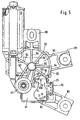
- the base body 20 now takes in addition to the gear elements further elements related to the control of the engine to serve. These are in particular an electronics unit 23 (see FIG. 5) and a contact plate 22 with contact tabs, which slide along appropriate switching tracks, which on Worm gear 6 are attached.
- a first area is used to house the Worm gear 6 and should therefore in the following gear chamber 25 are called. It is circular and has a depth which corresponds essentially to the height of the gear. As can be seen in Figure 3, the bottom of the Gear chamber inserted a contact plate 22 flat. Downtown the chamber is a pin 26 which is the axis the worm wheel 6 forms. This pin is in one corresponding recess 28 in the bottom 27 of the gear chamber held.
- the bottom has further depressions 28 ', 28' 'in which a suppression choke 29 or a capacitor 29 'is introduced are arranged on the underside of the contact plate 22 are.
- a groove connects to the gear chamber 25 30 on, in which the worm 5 on the extended motor shaft 4 is arranged.
- a breakthrough closes in the axial direction on the channel 30 on, which ends in the flange for the electric motor 1.
- the groove 30 is open to the gear chamber 25 so that the Worm 5 and the worm wheel 6 can come into contact.
- This area 31 is approximately square towards the outside limited, the bottom is flat, its depth is essential less than that of the gear chamber 25, so that between the Gear cam 25 and the swivel range 31 a step 32 is present.
- a cup-shaped Recording dome 41 provided to accommodate a bearing sleeve 40 is following Swivel area 31 and the gear chamber 25 .
- the edge of the recording dome 41 begins approximately at the level of the bottom of the swivel area 31
- Bottom 42 of the receiving dome 41 is still significantly below the bottom of the gear chamber 25.
- Downtown of the cathedral is the bearing sleeve 40, which is at the height of Bottom of the pivoting range 31 begins through the bottom 42 of the Domes 41 protrudes and extends beyond.
- stiffening struts 45 extend over the total height of the cathedral. Some of the struts are cut away, namely in the area that in the gear chamber 25 is enough.
- gear chamber 25, channel 30, swivel range 31 and the dome 41 are surrounded by an edge 50, whose upper edge runs at the same height and as a support surface 51 for the metal cover 17 and one if necessary seal inserted between the edge and lid.
- the edge 50 is for Part led to below the floor of the individual areas been. 5 that the lower edge area 52 the underside of the bottom 53 of the gear chamber 25 with approx. Encloses 180 degrees. From this over the bottom of the floor extended lower edge region 52 extend four ribs 54 to a central base 55, which is also protrudes from the underside of the bottom 53 and as in FIG 2 can be seen the reception of the pin 26 is used.
- the base 55 is approximately at the same height ends like the bottom 42 of the dome 41. Between the base 55 and the dome 41 run three stiffening ribs: the central one Rib 56 extends from the center of base 55 to the axis of the dome 41, two side ribs 57 each run tangentially into the base 55 or into the dome 41.
- the arrangement of the ribs was chosen because it was necessary is that the pin 26 is the axis of rotation of the worm wheel 6 and the axis of the drive shaft 11 if possible stay exactly aligned to each other when making noises Avoid operating the engine.
- the base 55 was not immediately connected to the bearing sleeve 40, but with interposition of the dome 41 with one opposite the bearing sleeve 40 enlarged diameters. With this, possible twists can be better absorbed by the ribs 56, 57.
- the bearing sleeve 40 itself is over the stiffening ribs 45 held firmly in the cathedral 41.
- the edge 50 in the region of the swivel range 31 is also behind pulled through below, so that on the of the swivel range 31 facing away from a receiving chamber 60 which the Includes control electronics 23.
- a cover 61 which closes this chamber, is partially cut away, so that a circuit board 62 can be seen on the electronic Switching elements are applied.
- the receiving chamber 60 is limited on the one hand by the downward drawn Edge, as well as by one of the ribs 54 and a side rib 57.
- a connector housing 70 is integrally formed on the side wall of the swivel area 31 or the receiving chamber 60 tangentially into the wall of the gear chamber 25 runs in.
- the connector housing With the connector housing it is a rectangular box 71, which is open at the top and bottom. Box 71 is separated by a partition 72 to the two open sides runs parallel, divided into two areas. Of the an area is open to the top of the case and is used to guide a plug, for which the inside of the Box is provided with corresponding guide grooves 73.
- the other area of the box that faces the bottom of the Housing 3 is open, is in addition to the receiving chamber 60 open so that the board 62 in this area of Box can protrude.
- openings 75 are provided in the receiving area 60 in. Protrude through these openings 75 Contact tabs 111, 117, 118 of the contact plate 22.
- Another opening 76 leads through from the receiving area 60 the bottom of the swivel area 31 into the swivel area. Its meaning is said to be related below the explanation of the contact plate 22 are described in more detail.
- fastening elements 80, 81 and 82 are on the outside of the housing three fastening elements 80, 81 and 82 arranged.
- these fasteners can be provided at any point of the housing, depending on how this requires the installation situation in the vehicle.
- the fasteners 80, 81 and 82 each consist of one Base with two parallel side walls 83, 84, which have the shape of a right triangle.
- a cathete the length of the triangle is equal to the height of the case 3 corresponds to and connects to the housing 3.
- In order to the other cathete extends perpendicularly from the housing wall from.
- the side walls 83, 84 close one between them Surface 85, which has a fastening eye 86 at the outer end having.
- the other part of the area can, as far as the Stiffness allowed to be broken.
- the fasteners 80, 81, 82 can each be arranged such that the eye 86 at the level of the housing cover 17, at the level of Bottom of the housing 3 or runs in the middle.
- the area, in which the electric motor is flanged has a recess 89 to accommodate a bearing for the motor shaft 4 on. They are also above and below the flange area Indentations 90, 91 are provided, in which fastening hooks engage with which the motor housing 92 on the housing is attached.
- the flange surface can either a plastic brush support plate 92a, which with corresponding Guide channels 93 for the brushes 94 of the electric motor are provided, put on or from the outset be made in one piece with the housing 3.
- a correspondingly folded holding plate 95 provided that with the contact plate 22 at the bottom of the housing 3 can be connected. To do this, makes a breakthrough the flange surface towards the gear chamber 25.
- tongues 96 are provided which reach through this opening and can be soldered to the contact plate.
- the holding plate has a tongue 96 which on the metallic housing jacket 97 of the electric motor can be.
- the previously mentioned elements that form the housing are molded from one piece of plastic and by injection molding manufactured.
- the plastic contains mineral fibers between 2 mm and 10 mm length. It also contains additives that the plastic resistant to weather influences (ozone) and thus the output shaft directly in the guide sleeve can be stored, give sliding properties.
- the bearing sleeve 40 insofar as it comes out of the dome 41 protruding outward, thickened. This corresponds to one put on veneer sleeve, which in the previous Housings that are not made of plastic, over the bearing sleeve visible on the outside of the vehicle is put over. Because the entire housing is made of plastic a separate veneer can be dispensed with. However, this generally presupposes that how already explained, the plastic made of weatherproof Material exists.
- the upper edge of the base body 20 formed plan so that the cover 17 can be placed there can. Since, as has already been explained below, the Cover 17 also serves as an axial support for the transmission (Cap 15), is an increased requirement on the flatness of the to put the top edge of the edge.
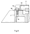
- the housing 3 is at several points with screws 160, their associated screw holes 102 in the edge of the housing are arranged, connected. Next to the screw holes 102 there are bumps 100 on the edge that define the screw hole over a pitch circle to the side surface of the housing 3 enclose. The amount of the survey is a little lower than the height of the seal 103 used between the Housing 3 and housing cover 17.
- the individual surveys 100 can easily be at the same height brought by after a first injection and after Cooling of the housing, the individual elevations 100 measured and the mold is reworked accordingly is, so that in the subsequently manufactured housings Surveys are all the same amount. Since the measurement is on defined points, namely at the surveys 100, post-processing of the form is easier to do because they only take place again at the appropriate places in the mold got to. This is easier than trying to do that to get the entire edge surface flat.
- the seal 103 itself is resilient so that when the Cover is screwed to the housing, the seal 103 is pressed down until the cover 17 on the elevations 100 rests.
- the contact plate 22 is punched out of a sheet, being between the individual Conductor tracks still remain holding bars, which after insertion of the contact plate 22 is cut into the housing 3 become.
- the main conductor track 101 has a central opening 102 through which the pin 26 for the worm wheel 6 extends through as soon as the contact plate 22 on the floor the gear chamber 25 rests.
- One belongs to the main line Contact spring 103 which is bent out of the plane of the contact plate and which at the end is a sublime contact 104, which has a corresponding conductor track on the Underside of the worm wheel interacts. Furthermore points a contact flag 105, which is located in the outer area of the Contact plate 22 is located.
- Another conductor track 106 runs approximately parallel to Contact spring 103 and carries a second at one end Contact tab 107 and at its other end a connector 108 for the choke 28.
- a third conductor track 109 which runs L-shaped on the outside of the contact plate, has a receptacle 110 for the other at one end End of the throttle 28 and ends in one at the other end first contact pin 111.
- This third conductor track 109 has a further connection 112 for the capacitor 29, the other end to one Connection 113 connects to the main conductor 101.
- a fourth conductor track 115 is provided with a contact spring 116, which, like the first contact spring 103, on its bent end is provided with a contact 117a which in another conductor track on the underside of the worm wheel 6 interacts. The other end of this trace 116 also ends in a second contact pin 117b, the is arranged next to the first contact pin 111.
- a third Contact pin 118 is located on the main conductor track 101. The three contact pins 111, 117, 118 are arranged side by side.
- the main conductor track 101 is in one piece with a cooling plate 120 connected. This extends perpendicular to the main conductor track 101 and is bent over with an L-shaped one Connector 121 connected. The top of the heat sink 120 is bent over and forms a contact surface 122 for the cover 17 of the housing. In the surface of the cooling plate 120, a tab 123 is punched out and bent out.
- the brush holder plate 95 has two bent Tongues that reach through this breakthrough, and contact the contact lugs 105 or 107.
- the contact pins 111, 117, 118 protrude through opening 75 in the floor the gear chamber 25 and get into the area the electronics holder 60. The corresponding pins are recognized one therefore also in FIG. 5.
- the cooling plate 120 protrudes through the opening 76 in the bottom of the Swivel range 31 through, so that the lower end of the can touch cooling units of the electronic unit.
- the upper, bent end is then at the level of the End edge of the housing so that the bent tab 122nd touches the lid 17.
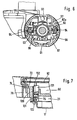
- circuit board 62 faces the electronics unit several contact pins in the connector housing 70 protrude. This is on average again in FIG. 7 shown. This figure shows a section through the housing in the area of the connector housing 70 and the electronics holder 60 or the swivel range.
- the circuit board 62 on which among other things, a power transistor 131 is soldered. With a cooling clamp 132 is connected to the power transistor 131. Transistor 131 and cooling clip 132 protrude through Breakthrough 76 in the bottom of the swivel area 31, wherein the cooling clamp 132 lies flat against the cooling plate 120.
- the bent tab 121 ensures that it is against the wall of the housing supports that the cooling flap 120 to a large area the cooling clamp 132 is present. It can also be seen that the bent end 122 abuts the cover 17. So that serves the cover 17 as a large-area cooling for the power transistor 131.
- the board 62 has multiple pins that are in the Project connector housing 70.
- the contact pins 111, 117, 118 of the contact plate 22, which protrude into the receiving area 60, are also with appropriate conductor tracks connected on the board 62.
- One of these interconnects connects the contact pin 118 on the main conductor 101 the ground pin in the connector housing 70. This will not only put a contact spring 103 to ground, but also the brush that contacts the contact tab 105.
- the lid is grounded.
- the design the brush holder ensures that the Ground lying area receives contact to the housing of the electric motor, which is flanged to the housing 3. In order to are all metallic parts, unless they are live serve, grounded. So the electric motor can to be easily suppressed.
- the second contact spring 116 supplied with power via the first contact pin 111 is over the third trace 109, which is over the capacitor grounded, the second brush is the contact tab 107 contacted, supplied with voltage via the choke.
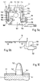
- the hole 141 in the sheet is conical, so that on one side of the sheet a relatively sharp edge 142 arises and on the other side a wide opening.
- the upper ends 143 of the pins are tapered educated.
- the contact disc 151 can preferably be oval, the long side being perpendicular to the upwardly open groove is introduced.
- the pin 26 is initially a or several circumferential grooves.
- the Molded around the spigot during injection molding of the housing On in this way the pin is held securely in the bottom of the housing.
- the pin can be symmetrical to Groove on one end with another groove on the other end be provided so that when loading the injection molding machine did not pay attention to the orientation of the pin are needed.
- the gearbox described so far also for a windscreen wiper washer is to be used is a water supply provided by the output shaft 11.
- This is in of Figure 11 shown in more detail.
- the supply line essentially exists from a brass tube 200 that is bent at one end is. This bent area is held by a holding part 201 surrounded by plastic that splashed around the tube becomes.
- the holding part 201 initially has a guide part 202 on, which is inserted into the hollow shaft, and that Tube 200 centered.
- the other end is a spout 203 formed on which a hose can be pushed can.
- the base body 204 is provided with undercuts, with which this bayonet-like in an opening in cover 17 can be used.
- the other end of the tube 200 is provided with a termination part 205, which at the same time serves as a support for a metal nozzle 206. That points to End part 205 has a recess in which the nozzle 206, whose outer contour is spherical, can be pressed. The nozzle 206 can now be aligned relative to the end part 205 be so that the wash water in a defined Area on the disc.
- the connector itself is provided with a central blind hole 207 in the receiving area the nozzle ends and into which the nozzle bore 208 flows into.
- the end part 205 sees a guide pin 209 that can be inserted into the metal tube 200, wherein the outer diameter of the pin 209 is approximately the inner diameter of the tube.
- the fit is allowed However, don't be too tight to fit the tubular spigot 209 can be inserted into the tube without kinking can.
- annular extension 210 is additionally provided, which is arranged coaxially to the tubular pin 209 is so that between the neck 210 and the tubular Pin 209 creates an annular groove, the width of the thickness corresponds to the pipe wall. Now the end of the tube is at his Roughened, milled or otherwise on the outside If the roughness of the surface is increased, it fits Tubes with sufficient clamping force in the ring groove between the approach 210 and the pin 209.
- the axial length of lug 210 is determined 50 that a sufficient clamping force can be generated, the length of the tubular pin 209 is determined so that sufficient Tightness of the carrier 205 in relation to the tube is effected.
Landscapes
- Engineering & Computer Science (AREA)
- Power Engineering (AREA)
- Mechanical Engineering (AREA)
- General Engineering & Computer Science (AREA)
- Connection Of Motors, Electrical Generators, Mechanical Devices, And The Like (AREA)
- Motor Or Generator Frames (AREA)
- General Details Of Gearings (AREA)
Abstract
Claims (5)
- Unité moteur-mécanisme comprenant un carter et un moteur électrique, le carter étant composé d'un corps de base (20) et présentant au moins une cavité destinée à loger des éléments de mécanisme d'un mécanisme, ainsi qu'un évidement destiné à loger des composants électriques pour le moteur, caractérisée en ce quel'évidement est prévu à côté de la cavité,les côtés ouverts de la cavité et de l'évidement sont disposés face à face, etune électronique de commande pour le moteur électrique est disposée dans l'évidement.
- Unité moteur-mécanisme selon la revendication I, caractérisée en ce que des fenêtres (75) sont prévues entre la cavité et l'évidement (60).
- Unité moteur-mécanisme selon la revendication 1 ou 2, caractérisée en ce qu'à l'évidement (60), se raccorde un boítier de connecteur (70) qui est d'une seule pièce avec le corps de base (20).
- Unité moteur-mécanisme selon une des revendications précédentes, caractérisée en ce qu'il est prévu une surface de bride à laquelle le moteur électrique peut être fixé, les balais (94) du moteur électrique étant prévus dans ou sur la surface de bride, et en ce que, dans la surface de bride, sont prévues des fenêtres qui conduisent à la cavité.
- Unité moteur-mécanisme selon la revendication 4, caractérisée en ce que les liaisons électriques entre le boítier de connecteur (70), l'électronique de commande, le moteur électrique et un commutateur actionné par le mécanisme sont réalisées par des pistes conductrices qui sont situées exclusivement dans le carter.
Applications Claiming Priority (7)
| Application Number | Priority Date | Filing Date | Title |
|---|---|---|---|
| DE19523589 | 1995-06-29 | ||
| DE19523589 | 1995-06-29 | ||
| DE19524628 | 1995-07-06 | ||
| DE19524628 | 1995-07-06 | ||
| DE19548867 | 1995-12-27 | ||
| DE19548867A DE19548867A1 (de) | 1995-06-29 | 1995-12-27 | Gehäuse für ein Getriebe |
| PCT/EP1996/002660 WO1997001465A1 (fr) | 1995-06-29 | 1996-06-19 | Carter pour mecanisme de transmission |
Publications (2)
| Publication Number | Publication Date |
|---|---|
| EP0835197A1 EP0835197A1 (fr) | 1998-04-15 |
| EP0835197B1 true EP0835197B1 (fr) | 1999-08-25 |
Family
ID=27215241
Family Applications (1)
| Application Number | Title | Priority Date | Filing Date |
|---|---|---|---|
| EP96922850A Expired - Lifetime EP0835197B1 (fr) | 1995-06-29 | 1996-06-19 | Bloc-moteur avec un carter et un moteur electrique |
Country Status (6)
| Country | Link |
|---|---|
| EP (1) | EP0835197B1 (fr) |
| JP (1) | JPH11508851A (fr) |
| CN (1) | CN1117000C (fr) |
| BR (1) | BR9608665A (fr) |
| ES (1) | ES2138823T3 (fr) |
| WO (1) | WO1997001465A1 (fr) |
Families Citing this family (3)
| Publication number | Priority date | Publication date | Assignee | Title |
|---|---|---|---|---|
| DE19847902B4 (de) * | 1998-10-18 | 2005-12-01 | Dr. Mirtsch Gmbh | Verfahren zur Umformung dünner, beulstrukturierter Materialbahnen |
| CN100361842C (zh) * | 2004-07-20 | 2008-01-16 | 通用汽车公司 | 电子通信线连接器、包括其的传动箱组件及其连接方法 |
| DE102021110071A1 (de) | 2021-04-21 | 2022-10-27 | Valeo Systèmes d'Éssuyage SAS | Scheibenwischermotor |
Family Cites Families (4)
| Publication number | Priority date | Publication date | Assignee | Title |
|---|---|---|---|---|
| DE1047648B (de) * | 1954-06-07 | 1958-12-24 | Gen Motors Corp | Scheibenwischergetriebe |
| DE3220191A1 (de) * | 1982-05-28 | 1983-12-01 | SWF-Spezialfabrik für Autozubehör Gustav Rau GmbH, 7120 Bietigheim-Bissingen | Elektrische antriebseinheit, insbesondere fuer scheibenwischer eines kraftfahrzeuges |
| US4857812A (en) * | 1986-07-07 | 1989-08-15 | Mitsuba Electric Mfg. Co., Ltd. | Electric motor system for automobiles |
| DE3930144A1 (de) * | 1989-09-09 | 1991-03-21 | Swf Auto Electric Gmbh | Elektrischer motor, insbesondere elektrischer kleinmotor zum antrieb von scheibenwischern an kraftfahrzeugen |
-
1996
- 1996-06-19 WO PCT/EP1996/002660 patent/WO1997001465A1/fr not_active Ceased
- 1996-06-19 BR BR9608665A patent/BR9608665A/pt not_active Application Discontinuation
- 1996-06-19 ES ES96922850T patent/ES2138823T3/es not_active Expired - Lifetime
- 1996-06-19 JP JP9504146A patent/JPH11508851A/ja active Pending
- 1996-06-19 EP EP96922850A patent/EP0835197B1/fr not_active Expired - Lifetime
- 1996-06-19 CN CN96195137A patent/CN1117000C/zh not_active Expired - Lifetime
Also Published As
| Publication number | Publication date |
|---|---|
| WO1997001465A1 (fr) | 1997-01-16 |
| ES2138823T3 (es) | 2000-01-16 |
| EP0835197A1 (fr) | 1998-04-15 |
| JPH11508851A (ja) | 1999-08-03 |
| BR9608665A (pt) | 1999-05-04 |
| CN1117000C (zh) | 2003-08-06 |
| CN1189133A (zh) | 1998-07-29 |
Similar Documents
| Publication | Publication Date | Title |
|---|---|---|
| EP0835198B1 (fr) | Carter d'un mecanisme | |
| DE19548867A1 (de) | Gehäuse für ein Getriebe | |
| EP0338394B1 (fr) | Moteur électrique, en particulier moteur d'essuie-glaces pour l'entraînement d'un dispositif d'essuie-glaces d'un véhicule | |
| EP0835196B1 (fr) | Mecanisme d'entrainement | |
| WO1997001468A1 (fr) | Piece de fermeture pour petit tube metallique | |
| EP0413801A1 (fr) | Essuie-glace. | |
| DE3020902A1 (de) | Elektronisches steuergeraet, insbesondere fuer kraftfahrzeuge | |
| DE4428883C1 (de) | Einrichtung für Kraftfahrzeuge | |
| EP0368115A2 (fr) | Comprimé buccal | |
| EP1282345B1 (fr) | Boîtier abritant une carte électronique avec ses composants dans un véhicule | |
| DE4429983C1 (de) | Elektrisches oder elektronisches Gerät für ein Kraftfahrzeug | |
| EP0789184A2 (fr) | Feu de signalisation allongé pour véhicules | |
| EP0868331B1 (fr) | Couvercle pour boitier pour dispositif d'entrainement | |
| EP0835197B1 (fr) | Bloc-moteur avec un carter et un moteur electrique | |
| EP1755930B1 (fr) | Couvercle pour logement de mecanisme d'entrainement d'un systeme d'essuie-glace | |
| DE3014490C2 (de) | Elektrischer Schalter mit Beleuchtungseinrichtung | |
| EP0835199B1 (fr) | Carter en matiere plastique | |
| DE3150060A1 (de) | "kraftfahrzeugteile und einbauanordnung hierfuer" | |
| WO1999059841A1 (fr) | Dispositif pour loger et maintenir une batterie | |
| EP1402615A1 (fr) | Partie de boitier pour entrainement d'ajustage electrique | |
| EP2026418B1 (fr) | Coque de boîtier comprenant une unité de construction intégrée dotée d'au moins un composant électromécanique | |
| EP0675515B1 (fr) | Interrupteur, en particulier pour le montage dans le tableau de bord d'un véhicule automobile, et procédé de fabrication d'un tel interrupteur | |
| DE3700583C2 (fr) | ||
| EP0264598B1 (fr) | Module de centrage pour le guidage et la réception d'une fiche de câble pouvant être blindée | |
| DE19848732A1 (de) | Elektrische Steckverbindung |
Legal Events
| Date | Code | Title | Description |
|---|---|---|---|
| PUAI | Public reference made under article 153(3) epc to a published international application that has entered the european phase |
Free format text: ORIGINAL CODE: 0009012 |
|
| 17P | Request for examination filed |
Effective date: 19980129 |
|
| AK | Designated contracting states |
Kind code of ref document: A1 Designated state(s): DE ES FR GB IT |
|
| 17Q | First examination report despatched |
Effective date: 19980415 |
|
| GRAG | Despatch of communication of intention to grant |
Free format text: ORIGINAL CODE: EPIDOS AGRA |
|
| GRAG | Despatch of communication of intention to grant |
Free format text: ORIGINAL CODE: EPIDOS AGRA |
|
| GRAG | Despatch of communication of intention to grant |
Free format text: ORIGINAL CODE: EPIDOS AGRA |
|
| GRAH | Despatch of communication of intention to grant a patent |
Free format text: ORIGINAL CODE: EPIDOS IGRA |
|
| GRAH | Despatch of communication of intention to grant a patent |
Free format text: ORIGINAL CODE: EPIDOS IGRA |
|
| GRAA | (expected) grant |
Free format text: ORIGINAL CODE: 0009210 |
|
| ITF | It: translation for a ep patent filed | ||
| AK | Designated contracting states |
Kind code of ref document: B1 Designated state(s): DE ES FR GB IT |
|
| GBT | Gb: translation of ep patent filed (gb section 77(6)(a)/1977) |
Effective date: 19990827 |
|
| REF | Corresponds to: |
Ref document number: 59602891 Country of ref document: DE Date of ref document: 19990930 |
|
| ET | Fr: translation filed | ||
| REG | Reference to a national code |
Ref country code: ES Ref legal event code: FG2A Ref document number: 2138823 Country of ref document: ES Kind code of ref document: T3 |
|
| PLBE | No opposition filed within time limit |
Free format text: ORIGINAL CODE: 0009261 |
|
| STAA | Information on the status of an ep patent application or granted ep patent |
Free format text: STATUS: NO OPPOSITION FILED WITHIN TIME LIMIT |
|
| 26N | No opposition filed | ||
| REG | Reference to a national code |
Ref country code: GB Ref legal event code: IF02 |
|
| PGFP | Annual fee paid to national office [announced via postgrant information from national office to epo] |
Ref country code: IT Payment date: 20080626 Year of fee payment: 13 |
|
| PGFP | Annual fee paid to national office [announced via postgrant information from national office to epo] |
Ref country code: GB Payment date: 20080605 Year of fee payment: 13 |
|
| GBPC | Gb: european patent ceased through non-payment of renewal fee |
Effective date: 20090619 |
|
| PG25 | Lapsed in a contracting state [announced via postgrant information from national office to epo] |
Ref country code: GB Free format text: LAPSE BECAUSE OF NON-PAYMENT OF DUE FEES Effective date: 20090619 |
|
| PG25 | Lapsed in a contracting state [announced via postgrant information from national office to epo] |
Ref country code: IT Free format text: LAPSE BECAUSE OF NON-PAYMENT OF DUE FEES Effective date: 20090619 |
|
| REG | Reference to a national code |
Ref country code: FR Ref legal event code: PLFP Year of fee payment: 20 |
|
| PGFP | Annual fee paid to national office [announced via postgrant information from national office to epo] |
Ref country code: ES Payment date: 20150629 Year of fee payment: 20 Ref country code: DE Payment date: 20150612 Year of fee payment: 20 |
|
| PGFP | Annual fee paid to national office [announced via postgrant information from national office to epo] |
Ref country code: FR Payment date: 20150630 Year of fee payment: 20 |
|
| REG | Reference to a national code |
Ref country code: DE Ref legal event code: R071 Ref document number: 59602891 Country of ref document: DE |
|
| REG | Reference to a national code |
Ref country code: ES Ref legal event code: FD2A Effective date: 20160926 |
|
| PG25 | Lapsed in a contracting state [announced via postgrant information from national office to epo] |
Ref country code: ES Free format text: LAPSE BECAUSE OF EXPIRATION OF PROTECTION Effective date: 20160620 |