EP0835381B1 - Pompe a fluide - Google Patents
Pompe a fluide Download PDFInfo
- Publication number
- EP0835381B1 EP0835381B1 EP96943027A EP96943027A EP0835381B1 EP 0835381 B1 EP0835381 B1 EP 0835381B1 EP 96943027 A EP96943027 A EP 96943027A EP 96943027 A EP96943027 A EP 96943027A EP 0835381 B1 EP0835381 B1 EP 0835381B1
- Authority
- EP
- European Patent Office
- Prior art keywords
- displacer
- pump
- outlet opening
- fluid
- fluid pump
- Prior art date
- Legal status (The legal status is an assumption and is not a legal conclusion. Google has not performed a legal analysis and makes no representation as to the accuracy of the status listed.)
- Expired - Lifetime
Links
Images



Classifications
-
- F—MECHANICAL ENGINEERING; LIGHTING; HEATING; WEAPONS; BLASTING
- F04—POSITIVE - DISPLACEMENT MACHINES FOR LIQUIDS; PUMPS FOR LIQUIDS OR ELASTIC FLUIDS
- F04B—POSITIVE-DISPLACEMENT MACHINES FOR LIQUIDS; PUMPS
- F04B43/00—Machines, pumps, or pumping installations having flexible working members
- F04B43/02—Machines, pumps, or pumping installations having flexible working members having plate-like flexible members, e.g. diaphragms
- F04B43/04—Pumps having electric drive
- F04B43/043—Micropumps
- F04B43/046—Micropumps with piezoelectric drive
Definitions
- the present invention relates to a fluid pump, i.e. a pump for liquids and gases.
- micropumps Corresponding pumps that are small in size and deliver low pump currents are called micropumps.
- the displacers of such pumps are typical designed as a membrane, see P. Gravesen, J. Branebjerg, O. S. Jensen; Microfluidics - A review; Micro Mechanics Europe Neuchatel, 1993, pages 143-164.
- the displacers can are driven by different mechanisms.
- Esashi, Micropump and sample injector for intrgrated chemical analyzing systems Sensors and actuators, A21-A23 (1990) pages 189-192, E. Stemme, G. Stemme; A valveless diffuser / nozzle-based fluid pump; Sensors & Actuators A, 39 (1993) 159-167, and T. Gerlach, H. Wurmus; Working principle and performance of the dynamic micropump; Proc. MEMS'95; (1995), pages 221-226; Amsterdam, The Netherlands, piezoelectric drive mechanisms are shown. Thermopneumatic mechanisms for driving the displacers are at F.C.M. Van de Pol, H.T.G. Van Lintel, M. Elwenspoek and J.H.J.
- micropumps can be either passive check valves or special flow nozzles are used, each time consuming are.
- the direction of delivery of micropumps can be without forced control of the valves solely by actuation with a frequency above the resonance frequency of the Valves are reversed.
- R. Zengerle S. Kluge, M. Richter, A. Richter; A. Bidirectional Silicon Micropump; Proc. MEMS'95; Amsterdam, Netherlands; Pages 19-24, J. Ulrich, H. Browner, R. Zengerle; Static and dynamic flow simulation through a KOH-etched micro valve; Proc. TRANSDUCERS '95, Sweden, (1995), pages 17-20.
- the cause of this effect is a phase shift between the movement of the displacer and the opening condition of the valves. If the phase difference is greater than 90 °, then the opening state of the valves counter to their state in normal forward mode and the pumping direction is reversed. An external changeover of the valves, as with macroscopic pumps is not necessary.
- the crucial one Phase difference between the displacer and the Valves depend on the one hand on the drive frequency of the Pump and on the other hand by the resonant frequency of the movable Valve part in the fluid environment.
- a disadvantage of this embodiment is that the execution of the valves a compromise between their mechanical Resonance in the fluid environment, its flow resistance, their fluidic capacity, i.e. the elastic Volume deformation, their size and their mechanical Stability must be found. These parameters that all can have an impact on the pump dynamics not independently adjusted to an optimum become and stand in part of a desired, further Miniaturization of the pump dimensions counter.
- a fluid pump is known, the one Pump body, a displacer and an elastic buffer having.
- the displacer closes in a first end position an inlet arranged in the pump body and leaves in a second end position in the pump body arranged inlet open.
- the known pump enables a net flow through one also in the pump body arranged outlet.
- the to the through the displacer and the Pump body formed pump chamber adjacent buffer device makes the known fluid pump complex.
- the valve consists of a glass plate in which a gas outlet opening is arranged by means of a silicon mesa structure that can be operated by a piezoelectric drive, which is provided with a valve seat, is lockable.
- the silicon layer in which the silicon mesa structure is formed, and define the glass plate also a continuous channel between the Gas outlet opening and a gas inlet opening, which in the Silicon layer is formed.
- DE 42 23 019 C discloses a fluid pump with a Pump body, a displacer, the displacer and the Pump bodies are designed such that between them a pump chamber is formed which has an inlet opening and has an outlet opening, the inlet opening and the Check valve are not provided with check valves, a drive device that periodically in the displacer positioned a first and a second end position.
- the present Invention Based on the prior art mentioned, the present Invention based on the task of efficient To create a fluid pump with a simple structure.
- the present invention provides a fluid pump with a Pump body and a displacer, which is by means of a drive periodically in a first and a second end position is positionable, the displacer and the pump body are formed such that between them Pump chamber is formed, which has an inlet opening and a Has outlet opening.
- the displacer closes the outlet opening, when he is in the first end position, and leaves the outlet opening is open when it is in the second end position is.
- the pump body is preferably in shape a plate which has the inlet and outlet openings, trained while the displacer has a recess which defines the pump chamber.
- the pump efficiency is due to an adjustment of the cross-sectional areas the inlet and outlet opening, as well as through a control of the timing of driving the displacer can be optimized in the first and second end positions.
- the displacer can be driven by a piezoelectric Bending converter, a glued-on piezo plate or electrostatically.
- a fluid pump according to the present invention has one simple structure based on a single structured Silicon chip can exist. This can result in costs in processing the silicon parts and costs in the Assembly can be saved. Another cost saving results by manufacturing a pump according to the invention Plastic using precision engineering processes, for example Injection molding, etc.
- the displacer of the fluid pump according to the invention is equipped with a Driven driver voltage, which has such a polarity, that the displacer is raised. After switching off the pump can reverse the polarity of the drive voltage be, whereby the outlet opening with a defined high Contact pressure is closed. This creates the outlet opening together with the displacer represents an active valve, which is a major advantage over passive valves represents. By introducing a small buffer volume in the pumping chamber can also be the pumping direction Fluid pump according to the present invention reversed become, which in most cases is a use of a second pump is unnecessary.
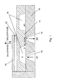
- a preferred embodiment is one Fluid pump shown according to the present invention.
- the Pump has a pump body 10 and a displacer 12 on.
- In the pump body is an outlet opening 14 with a Width w and an inlet opening 16 are formed.
- the outlet opening 14 and the inlet opening 16 can be any Shape, for example square, round, rectangular or ellipsoid, exhibit.
- the displacer 12 is on the pump body 10 attached and has a recess that together with the pump body 10 defines a pump chamber 18. Of the Pump body 10 and the displacer 12 can for example be circular.
- the displacer 12 is by means of a piezo bending transducer 20, which consists of piezoceramic, in a first and a second End position movable back and forth.
- the piezo bending transducer 20 is for example by means of an adhesive 22 on the displacer 12 attached.
- the displacer 12 forms on its middle, thicker section a valve with the outlet opening 14, the outlet opening 14 in the first end position of the Displacer 12 is closed and in the second end position of the displacer 12 is open.
- the inlet opening which is designed as an aperture can be open permanently.
- FIG. 1 A general view of the operation of the pump according to FIG. 1 follows. With the movement of the displacer 12, both a pressure p in the pump chamber 18 and a gap height h at the outlet opening 14 change. The flow through the outlet opening depends on these two Factors, the pressure p and the gap height h. In a simplified view, there is a flow ⁇ proportional to ph 3 , the relationship being p x h y with any number x and y in a more general view.
- FIG. 2 shows the pressure curve in the pump chamber over time 18 when triggering the piezo bending transducer 20 with a Rectangular voltage shown.
- ⁇ Inlet A Inlet ⁇ 2nd p 1 -p ⁇
- a orifice is the cross-sectional area of the inlet opening or orifice 16
- ⁇ is a geometry-dependent dimensionless discharge number
- ⁇ is the density of the fluid
- p 1 is the pressure in the inlet opening into the inlet opening (see FIG. 1)
- p is the pump chamber pressure.
- W is the width of the outlet opening
- h is the displacement of the displacer
- b is the length of the corresponding gap (see FIG. 1)
- ⁇ is the viscosity of the fluids
- p 2 is the pressure in the outlet opening into the outlet opening (see Fig. 1).
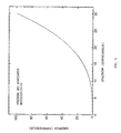
- the flow through the outlet opening depending on the The gap height h is for a constant pressure difference in FIG. 3 shown. Especially for small gap heights h Flow drastically reduced.
- the decisive factor for the pump mechanism is the fluid pump according to the present invention the fact that the flow through the outlet opening from the two independent variables, namely the pump chamber pressure p and the gap height h depends.
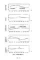
- the transient processes are during the suction and during the pressure phase in the pump according to Fig. 1 shown in diagram form.
- FIG. 4a shows the course of the displacement movement
- FIG. 4b the course of the pump chamber pressure p
- FIG. 4c the flow through the inlet opening
- Fig. 4d the flow through the Exhaust port shown.
- the net pumping effect of the fluid pump of the present invention rests on the gap between the displacer and the outlet opening during the opening process of the outlet opening, So the suction phase, and the closing process of the Exhaust opening, i.e. the pressure phase, flows through differently becomes.
- the reason for this is that the flow through the outlet both from the pressure in the pumping chamber as well as the gap height h between the displacer and the Pump body depends.
- the pumping efficiency of a pump according to the present invention i.e. the pump yield per pump cycle
- Modification of the two opening cross-sections can be varied. In particular, this results in a reduction in the cross-sectional area the inlet opening in relation to the cross-sectional area, i.e. the width w of the outlet opening, an increase of the maximum pressure.
- the printing efficiency can also by improved an optimized course of the control voltage become.
- the pressure in the pump chamber arises for a given control voltage U so that there is a balance of forces between the pump drive, the intrinsic tension of the Displacer and the hydrostatic pressure of the fluid in the Pump chamber results.
- 6a, 6b and 6c are two possibilities shown how the pressure in the pumping chamber advantageously modified by a suitable control voltage can be.
- the voltage profiles in FIGS. 6a to 6c is a linear one Voltage increase during the suction phase and an abrupt one Switch off the voltage together during the printing phase. Furthermore, the voltage curve of FIG. 6c also increases At the beginning of the printing phase, the voltage is reversed, causing the pressure in the pumping chamber increases beyond the normal level becomes. With such control voltages, the Targeted increase in pump efficiency. It is also obvious that the displacer either by its mechanical Restoring force due to its deformation (passive) or can be closed via the drive (active).
- the crucial point in the pump mechanism according to the present invention is therefore that with the movement of the displacer, both the pressure p in the pump chamber and the height of the flow gap at the outlet opening change.
- the flow through the outlet opening is composed of these two factors.
- the flow ⁇ is proportional to ph 3
- the flow is proportional to p x h y , where x and y are arbitrary numbers.
- FIG. 7 A such a pressure curve is shown in FIG. 7.
- Such a Pressure course can be, for example, by means of an electrostatic Drive or a targeted modification of the control voltage (see Fig. 6) can be achieved.
- the pump body 100 is made thereby from a fluidic base plate with integrated channels 105 and 107, which are in an outlet opening 140 and an inlet opening, respectively 160 ends.
- a structured one serves as displacer 120 Silicon chip attached to the fluidic base plate is and is configured to in a first end position to close the outlet opening 140 and in a second end position to leave the outlet opening open.
- a recess in the displacer 120 is also a pump chamber 180 defined.
- the drive shown in Fig. 8 Embodiment attached to the displacer Piezo ceramic plate used on the top provide it with a layer for selective bonding can be.
- FIG. 9 is another embodiment of the present Invention shown that with the exception of the drive of the displacer is the same as the embodiment of FIG. 8.
- a electrostatic drive of the displacer realized. To is over the side opposite the pump body 100 of the displacer 120 is spaced apart by a counter electrode arranged to the displacer in the first and the to move to the second end position.
- An electrostatic drive has the advantage that it is based solely on the non-linear electrostatic driving forces during suction and the pressure phase a strongly asymmetrical pump chamber pressure curve, as shown for example in Fig. 7 is enabled.
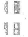
- 10a to 10d are further exemplary embodiments shown for the control of the displacer. It can between a selective or areal application of force be distinguished.
- the control devices also differ by whether it is a positively driven control or control with retroactive effect enable. With a positively controlled displacer exists between the displacement position and the pump chamber pressure no retroactive effect.
- 10a shows a drive for selective application of force without forced control.
- 10b is a drive for a flat application of force to the displacer without Forced control shown.
- 10c and 10d are Drives for selective or areal application of force represented with a forced control.
- the aperture i.e. the inlet opening
- the aperture form as a flow nozzle
- Diffuser nozzle pumps is common. This will further the pumping direction further benefits.
- the elastic components can for example an elastic membrane or an elastic one Media inclusion, for example gas.
- the transients Processes in a pump for this case are shown in Fig. 11.
- the resonance frequency is in the fluid to be moved Co-determined fluid lines. This will, for example Cut-off frequency above which a reversal of the conveying direction occurs, with increasing length of the fluid lines because of larger fluid mass less. Through a targeted introduction of elastic components outside the pump chamber this unwanted coupling between the resonance frequency and suppress the fluid lines.
- a reversal of the pump direction can also be achieved by exploiting the dynamic behavior of the displacer becomes. If the pump is operated at a frequency that the Corresponds to the resonance frequency of the displacer, leads to a phase shift between the one that drives the displacer Force and movement of the displacer to reverse the Pump direction.
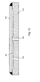
- FIG. 12 shows a further exemplary embodiment of a fluid pump according to the present invention.
- the fluid pump shown in FIG. 12 is a pump chamber 380 between a pump body 310 and a displacer 320 as a capillary gap is formed. With such an arrangement the filling can be significantly simplified because a fluid is drawn into the pumping chamber due to the capillary forces becomes.
- Fig. 12 is the drive mechanism for the Displacement device not shown.
- a fluid pump according to the present invention can also be provided with a pressure sensor via which the fluid pump is kept in the ideal operating range.
- the pressure sensor can be arranged in or on the pump chamber, around which in the same prevailing pressure.
- the Pressure sensor in the embodiment shown in FIG. 12 for example in the form of a membrane Displacer 320 can be integrated. It's about a control loop then possible to drive the micropump in the optimum Bring workspace.
Landscapes
- Engineering & Computer Science (AREA)
- Mechanical Engineering (AREA)
- General Engineering & Computer Science (AREA)
- Reciprocating Pumps (AREA)
- Fluid-Driven Valves (AREA)
Claims (14)
- Pompe à fluide comportantun corps de pompe (10; 100; 310);un organe de refoulement (12; 120; 320), l'organe de refoulement (12; 120; 320) et le corps de pompe (10; 100; 310) étant conçus de façon qu'entre eux soit formée une chambre de pompe (18; 180; 380) qui présente une ouverture d'entrée (16; 160; 360) et une ouverture de sortie (14; 140; 340), l'ouverture d'entrée (16; 160; 360) et l'ouverture de sortie (14; 140; 340) n'étant pas munies de clapets de non-retour;un dispositif d'entraínement (20; 200; 210) qui positionne périodiquement l'organe de refoulement (12; 120; 320) dans une première et une seconde positions d'extrémité, caractérisée par le faitque l'organe de refoulement (12; 120; 320) obture l'ouverture de sortie (14; 140; 340) lorsqu'il est dans la première position d'extrémité, laisse ouverte l'ouverture de sortie (14; 140; 340) lorsqu'il est dans la seconde position d'extrémité, et laisse ouverte l'ouverture d'entrée (16; 160; 360) dans les deux positions d'extrémité,que, lors de son mouvement pour passer de la première à la seconde position d'extrémité, l'organe de refoulement (12; 120; 320) définit, dans la zone de l'ouverture de sortie (14; 140; 340), entre l'organe de refoulement et le corps de pompe, une fente d'écoulement, s'ouvrant en fonction dudit mouvement, de façon que l'écoulement à travers l'ouverture de sortie (14; 140; 340) dépende aussi bien de la pression régnant dans la chambre de pompe (18; 180; 380) que du taux d'ouverture respectif de la fente d'écoulement.
- Pompe à fluide selon la revendication 1, caractérisée par le faitque le corps de pompe (10; 100) a la forme d'une plaque qui comprend l'ouverture d'entrée et l'ouverture de sortie et que l'organe de refoulement (12; 120) présente un évidement qui, avec le corps de pompe (10; 100), définit la chambre de pompe (18; 180).
- Pompe à fluide selon la revendication 1, caractérisée par le faitque le corps de pompe (310) a la forme d'une plaque qui comprend l'ouverture d'entrée et l'ouverture de sortie (360, 340), le corps de pompe (310) présentant en outre un évidement qui, avec l'organe de refoulement (320) définit la chambre de pompe.
- Pompe à fluide selon l'une des revendications 1 à 3, caractérisée par le fait que la chambre de pompe (380) est conçue sous forme d'une fente capillaire.
- Pompe à fluide selon l'une des revendications 1 à 4, caractérisée par le fait que l'aire de la section de l'ouverture d'entrée (16; 160; 360) est réduite par rapport à l'aire de la section d'ouverture de sortie (14; 140; 340).
- Pompe à fluide selon l'une des revendications 1 à 5, caractérisée par le fait que le mécanisme d'entraínement est un transducteur de cintrage piézo-électrique (20).
- Pompe à fluide selon l'une des revendications 1 à 6, caractérisée par le fait que le mécanisme d'entraínement est constitué d'une piézo-plaque (200) rapportée sur la face de l'organe de refoulement (120) située en face du corps de pompe (100).
- Pompe à fluide selon l'une des revendications 1 à 7, caractérisée par le fait que le mécanisme d'entraínement est un mécanisme d'entraínement électrostatique (210).
- Pompe à fluide selon l'une des revendications 1 à 8, caractérisée par le fait que l'organe de refoulement (12; 120; 320) obture passivement l'ouverture de sortie (14; 140; 340) après mise hors circuit de la pompe.
- Pompe à fluide selon l'une des revendications 1 à 8, caractérisée par le fait que l'organe de refoulement (12; 120; 320) obture l'ouverture de sortie (14; 140; 340) par application, sur le dispositif d'entraínement, d'une tension de signe opposé.
- Pompe à fluide selon l'une des revendications 1 à 10, caractérisée par le fait que dans ou sur la chambre de pompe (18; 180; 380) est disposé un détecteur de pression avec lequel est construit un circuit de régulation.
- Procédé d'entraínement d'une pompe à fluide selon l'une des revendications 1 à 11, caractérisépar le fait que pendant une phase d'aspiration, au cours de laquelle l'organe de refoulement (12; 120; 320) est déplacé de la première à la seconde position d'extrémité, une tension de croissance sensiblement linéaire est appliquée au mécanisme d'entraínement, etqu'au début d'une phase de compression, au cours de laquelle l'organe de refoulement (12; 120; 320) est déplacé de la seconde à la première position d'extrémité, la tension qui s'applique au mécanisme d'entraínement est brusquement supprimée.
- Procédé selon la revendication 12, caractérisépar le fait qu'au début de la phase de compression, après la brusque suppression de la tension, c'est une tension de signe opposé qui est appliquée au mécanisme d'entraínement.
- Procédé d'entraínement d'une pompe à fluide selon l'une des revendications 1 à 11, caractérisépar le fait que l'organe de refoulement (12; 120; 320) est entraíné par lc mécanisme d'entraínement (20; 200; 210) à une fréquence qui correspond à la fréquence de résonance de la colonne de fluide déplacée ou à la fréquence de résonance de l'organe de refoulement (12; 120; 320).
Applications Claiming Priority (3)
| Application Number | Priority Date | Filing Date | Title |
|---|---|---|---|
| DE19546570 | 1995-12-13 | ||
| DE19546570A DE19546570C1 (de) | 1995-12-13 | 1995-12-13 | Fluidpumpe |
| PCT/EP1996/005382 WO1997021924A1 (fr) | 1995-12-13 | 1996-12-03 | Pompe a fluide |
Publications (2)
| Publication Number | Publication Date |
|---|---|
| EP0835381A1 EP0835381A1 (fr) | 1998-04-15 |
| EP0835381B1 true EP0835381B1 (fr) | 1999-02-10 |
Family
ID=7780035
Family Applications (1)
| Application Number | Title | Priority Date | Filing Date |
|---|---|---|---|
| EP96943027A Expired - Lifetime EP0835381B1 (fr) | 1995-12-13 | 1996-12-03 | Pompe a fluide |
Country Status (5)
| Country | Link |
|---|---|
| US (1) | US6109889A (fr) |
| EP (1) | EP0835381B1 (fr) |
| AT (1) | ATE176715T1 (fr) |
| DE (2) | DE19546570C1 (fr) |
| WO (1) | WO1997021924A1 (fr) |
Families Citing this family (115)
| Publication number | Priority date | Publication date | Assignee | Title |
|---|---|---|---|---|
| US5919582A (en) * | 1995-10-18 | 1999-07-06 | Aer Energy Resources, Inc. | Diffusion controlled air vent and recirculation air manager for a metal-air battery |
| DE19648694C1 (de) * | 1996-11-25 | 1998-04-30 | Vermes Mikrotechnik Gmbh | Bidirektionale dynamische Mikropumpe |
| DE19719862A1 (de) * | 1997-05-12 | 1998-11-19 | Fraunhofer Ges Forschung | Mikromembranpumpe |
| US7485263B2 (en) * | 1997-08-26 | 2009-02-03 | Eppendorf Ag | Microproportioning system |
| US6368079B2 (en) * | 1998-12-23 | 2002-04-09 | Battelle Pulmonary Therapeutics, Inc. | Piezoelectric micropump |
| US6179586B1 (en) * | 1999-09-15 | 2001-01-30 | Honeywell International Inc. | Dual diaphragm, single chamber mesopump |
| EP1128075A3 (fr) * | 2000-02-24 | 2003-10-29 | Fraunhofer-Gesellschaft Zur Förderung Der Angewandten Forschung E.V. | Micropompe et/ou micromélangeur à capteur intégré, et procédé pour sa fabrication |
| US6296452B1 (en) * | 2000-04-28 | 2001-10-02 | Agilent Technologies, Inc. | Microfluidic pumping |
| US7553453B2 (en) | 2000-06-02 | 2009-06-30 | Honeywell International Inc. | Assay implementation in a microfluidic format |
| US7242474B2 (en) * | 2004-07-27 | 2007-07-10 | Cox James A | Cytometer having fluid core stream position control |
| US7262838B2 (en) * | 2001-06-29 | 2007-08-28 | Honeywell International Inc. | Optical detection system for flow cytometry |
| US8071051B2 (en) | 2004-05-14 | 2011-12-06 | Honeywell International Inc. | Portable sample analyzer cartridge |
| US7471394B2 (en) * | 2000-08-02 | 2008-12-30 | Honeywell International Inc. | Optical detection system with polarizing beamsplitter |
| US7630063B2 (en) * | 2000-08-02 | 2009-12-08 | Honeywell International Inc. | Miniaturized cytometer for detecting multiple species in a sample |
| US7283223B2 (en) * | 2002-08-21 | 2007-10-16 | Honeywell International Inc. | Cytometer having telecentric optics |
| US8383043B2 (en) * | 2004-05-14 | 2013-02-26 | Honeywell International Inc. | Analyzer system |
| US7016022B2 (en) * | 2000-08-02 | 2006-03-21 | Honeywell International Inc. | Dual use detectors for flow cytometry |
| US7978329B2 (en) * | 2000-08-02 | 2011-07-12 | Honeywell International Inc. | Portable scattering and fluorescence cytometer |
| US7215425B2 (en) * | 2000-08-02 | 2007-05-08 | Honeywell International Inc. | Optical alignment for flow cytometry |
| US6970245B2 (en) * | 2000-08-02 | 2005-11-29 | Honeywell International Inc. | Optical alignment detection system |
| US7130046B2 (en) * | 2004-09-27 | 2006-10-31 | Honeywell International Inc. | Data frame selection for cytometer analysis |
| US7641856B2 (en) * | 2004-05-14 | 2010-01-05 | Honeywell International Inc. | Portable sample analyzer with removable cartridge |
| US8329118B2 (en) * | 2004-09-02 | 2012-12-11 | Honeywell International Inc. | Method and apparatus for determining one or more operating parameters for a microfluidic circuit |
| US7420659B1 (en) | 2000-06-02 | 2008-09-02 | Honeywell Interantional Inc. | Flow control system of a cartridge |
| US20060263888A1 (en) * | 2000-06-02 | 2006-11-23 | Honeywell International Inc. | Differential white blood count on a disposable card |
| US6297576B1 (en) * | 2000-06-22 | 2001-10-02 | Agilent Technologies, Inc. | Piezoelectric actuator |
| US7061595B2 (en) * | 2000-08-02 | 2006-06-13 | Honeywell International Inc. | Miniaturized flow controller with closed loop regulation |
| US7277166B2 (en) * | 2000-08-02 | 2007-10-02 | Honeywell International Inc. | Cytometer analysis cartridge optical configuration |
| US6382228B1 (en) * | 2000-08-02 | 2002-05-07 | Honeywell International Inc. | Fluid driving system for flow cytometry |
| CN1269637C (zh) * | 2000-09-18 | 2006-08-16 | 帕尔技术有限责任公司 | 一种压电致动器和使用压电致动器的泵 |
| US7198250B2 (en) * | 2000-09-18 | 2007-04-03 | Par Technologies, Llc | Piezoelectric actuator and pump using same |
| DE10065855A1 (de) * | 2000-12-22 | 2002-07-04 | Bsh Bosch Siemens Hausgeraete | Dosiervorrichtung zur Förderung geringer Stoffmengen |
| US6878755B2 (en) * | 2001-01-22 | 2005-04-12 | Microgen Systems, Inc. | Automated microfabrication-based biodetector |
| WO2002079703A2 (fr) | 2001-02-13 | 2002-10-10 | Technology Applications, Inc. | Pompes a chaleur et moteurs alternatifs miniatures |
| DE10136904A1 (de) * | 2001-07-28 | 2003-02-20 | Eppendorf Ag | Vorrichtung zum Fördern und/oder Dosieren kleinste Fluidmengen |
| US6715733B2 (en) * | 2001-08-08 | 2004-04-06 | Agilent Technologies, Inc. | High temperature micro-machined valve |
| US6554591B1 (en) * | 2001-11-26 | 2003-04-29 | Motorola, Inc. | Micropump including ball check valve utilizing ceramic technology and method of fabrication |
| US6561224B1 (en) | 2002-02-14 | 2003-05-13 | Abbott Laboratories | Microfluidic valve and system therefor |
| JP4378937B2 (ja) * | 2002-06-03 | 2009-12-09 | セイコーエプソン株式会社 | ポンプ |
| US7090471B2 (en) * | 2003-01-15 | 2006-08-15 | California Institute Of Technology | Integrated electrostatic peristaltic pump method and apparatus |
| DE20313727U1 (de) * | 2003-09-04 | 2005-01-13 | Thinxxs Gmbh | Piezoaktor |
| EP1515043B1 (fr) * | 2003-09-12 | 2006-11-22 | Samsung Electronics Co., Ltd. | Pompe à membrane pour air de refroidissement |
| CN100427759C (zh) * | 2003-09-12 | 2008-10-22 | 清华大学 | 双压电梁驱动的膜片气泵 |
| US20050232817A1 (en) * | 2003-09-26 | 2005-10-20 | The University Of Cincinnati | Functional on-chip pressure generator using solid chemical propellant |
| US7290993B2 (en) * | 2004-04-02 | 2007-11-06 | Adaptivenergy Llc | Piezoelectric devices and methods and circuits for driving same |
| US20050225201A1 (en) * | 2004-04-02 | 2005-10-13 | Par Technologies, Llc | Piezoelectric devices and methods and circuits for driving same |
| US7312554B2 (en) | 2004-04-02 | 2007-12-25 | Adaptivenergy, Llc | Piezoelectric devices and methods and circuits for driving same |
| US7287965B2 (en) * | 2004-04-02 | 2007-10-30 | Adaptiv Energy Llc | Piezoelectric devices and methods and circuits for driving same |
| US7612871B2 (en) * | 2004-09-01 | 2009-11-03 | Honeywell International Inc | Frequency-multiplexed detection of multiple wavelength light for flow cytometry |
| US7630075B2 (en) | 2004-09-27 | 2009-12-08 | Honeywell International Inc. | Circular polarization illumination based analyzer system |
| US7222639B2 (en) * | 2004-12-29 | 2007-05-29 | Honeywell International Inc. | Electrostatically actuated gas valve |
| US7258533B2 (en) * | 2004-12-30 | 2007-08-21 | Adaptivenergy, Llc | Method and apparatus for scavenging energy during pump operation |
| US20060147329A1 (en) * | 2004-12-30 | 2006-07-06 | Tanner Edward T | Active valve and active valving for pump |
| US7328882B2 (en) | 2005-01-06 | 2008-02-12 | Honeywell International Inc. | Microfluidic modulating valve |
| US7445017B2 (en) * | 2005-01-28 | 2008-11-04 | Honeywell International Inc. | Mesovalve modulator |
| US20060232166A1 (en) * | 2005-04-13 | 2006-10-19 | Par Technologies Llc | Stacked piezoelectric diaphragm members |
| JP2008537461A (ja) * | 2005-04-13 | 2008-09-11 | アダプティブエナジー・リミテッド・ライアビリティー・カンパニー | フレキシブル膜上に導体を備える圧電ダイヤフラムアセンブリ |
| US7688427B2 (en) * | 2005-04-29 | 2010-03-30 | Honeywell International Inc. | Particle parameter determination system |
| WO2007005974A2 (fr) | 2005-07-01 | 2007-01-11 | Honeywell International, Inc. | Analyseur debitmetrique |
| JP2009500612A (ja) | 2005-07-01 | 2009-01-08 | ハネウェル・インターナショナル・インコーポレーテッド | 流量測定分析器 |
| EP1902298B1 (fr) | 2005-07-01 | 2012-01-18 | Honeywell International Inc. | Cartouche moulee a focalisation hydrodynamique dans 3 dimensions |
| US7517201B2 (en) | 2005-07-14 | 2009-04-14 | Honeywell International Inc. | Asymmetric dual diaphragm pump |
| US7843563B2 (en) * | 2005-08-16 | 2010-11-30 | Honeywell International Inc. | Light scattering and imaging optical system |
| US20070051415A1 (en) * | 2005-09-07 | 2007-03-08 | Honeywell International Inc. | Microvalve switching array |
| US20070075286A1 (en) * | 2005-10-04 | 2007-04-05 | Par Technologies, Llc | Piezoelectric valves drive |
| US20070129681A1 (en) * | 2005-11-01 | 2007-06-07 | Par Technologies, Llc | Piezoelectric actuation of piston within dispensing chamber |
| US7345407B2 (en) * | 2005-11-18 | 2008-03-18 | Adaptivenergy, Llc. | Human powered piezoelectric power generating device |
| DE102005055697B4 (de) * | 2005-11-23 | 2011-12-29 | Allmendinger Elektromechanik Gmbh | Vorrichtung zur dosierten Abgabe eines Fluids und Gerät mit einer solchen Vorrichtung |
| US7624755B2 (en) | 2005-12-09 | 2009-12-01 | Honeywell International Inc. | Gas valve with overtravel |
| JP2009521684A (ja) | 2005-12-22 | 2009-06-04 | ハネウェル・インターナショナル・インコーポレーテッド | 携帯用サンプル分析装置のカートリッジ |
| WO2007075919A2 (fr) | 2005-12-22 | 2007-07-05 | Honeywell International Inc. | Systeme d'analyseur portatif d'echantillons |
| US7523762B2 (en) | 2006-03-22 | 2009-04-28 | Honeywell International Inc. | Modulating gas valves and systems |
| US7543604B2 (en) * | 2006-09-11 | 2009-06-09 | Honeywell International Inc. | Control valve |
| US7644731B2 (en) | 2006-11-30 | 2010-01-12 | Honeywell International Inc. | Gas valve with resilient seat |
| US20080246367A1 (en) * | 2006-12-29 | 2008-10-09 | Adaptivenergy, Llc | Tuned laminated piezoelectric elements and methods of tuning same |
| TW200839495A (en) * | 2007-03-30 | 2008-10-01 | Cooler Master Co Ltd | Structure of water cooling head |
| US20080260552A1 (en) * | 2007-04-17 | 2008-10-23 | Hsiao-Kang Ma | Membrane pump |
| US20080260553A1 (en) * | 2007-04-17 | 2008-10-23 | Hsiao-Kang Ma | Membrane pump device |
| JP2009083382A (ja) * | 2007-10-01 | 2009-04-23 | Brother Ind Ltd | 画像形成装置および画像処理プログラム |
| US8746130B2 (en) | 2007-10-22 | 2014-06-10 | Fraunhofer-Gesellschaft Zur Foerderung Der Angewandten Forschung E.V. | Diaphragm pump |
| US20100034704A1 (en) * | 2008-08-06 | 2010-02-11 | Honeywell International Inc. | Microfluidic cartridge channel with reduced bubble formation |
| US8037354B2 (en) | 2008-09-18 | 2011-10-11 | Honeywell International Inc. | Apparatus and method for operating a computing platform without a battery pack |
| EP2469089A1 (fr) * | 2010-12-23 | 2012-06-27 | Debiotech S.A. | Procédé de contrôle électronique et système pour pompe piézo-électrique |
| EP2479466A1 (fr) * | 2011-01-21 | 2012-07-25 | Biocartis SA | Micro-pompe ou microvanne normalement fermée |
| US20120251335A1 (en) * | 2011-04-01 | 2012-10-04 | Gregg Hurst | Pump controller with multiphase measurement |
| WO2012176171A1 (fr) | 2011-06-23 | 2012-12-27 | Debiotech S.A. | Réservoir désaéré pour pompe médicale |
| DE102011086042A1 (de) * | 2011-11-09 | 2013-05-16 | Johnson Matthey Catalysts (Germany) Gmbh | Biegewandler sowie Mikropumpe mit einem Biegewandler |
| US9851103B2 (en) | 2011-12-15 | 2017-12-26 | Honeywell International Inc. | Gas valve with overpressure diagnostics |
| US8905063B2 (en) | 2011-12-15 | 2014-12-09 | Honeywell International Inc. | Gas valve with fuel rate monitor |
| US9835265B2 (en) | 2011-12-15 | 2017-12-05 | Honeywell International Inc. | Valve with actuator diagnostics |
| US9846440B2 (en) | 2011-12-15 | 2017-12-19 | Honeywell International Inc. | Valve controller configured to estimate fuel comsumption |
| US9074770B2 (en) | 2011-12-15 | 2015-07-07 | Honeywell International Inc. | Gas valve with electronic valve proving system |
| US9557059B2 (en) | 2011-12-15 | 2017-01-31 | Honeywell International Inc | Gas valve with communication link |
| US8947242B2 (en) | 2011-12-15 | 2015-02-03 | Honeywell International Inc. | Gas valve with valve leakage test |
| US8839815B2 (en) | 2011-12-15 | 2014-09-23 | Honeywell International Inc. | Gas valve with electronic cycle counter |
| US9995486B2 (en) | 2011-12-15 | 2018-06-12 | Honeywell International Inc. | Gas valve with high/low gas pressure detection |
| US8899264B2 (en) | 2011-12-15 | 2014-12-02 | Honeywell International Inc. | Gas valve with electronic proof of closure system |
| US8741234B2 (en) | 2011-12-27 | 2014-06-03 | Honeywell International Inc. | Disposable cartridge for fluid analysis |
| US8663583B2 (en) | 2011-12-27 | 2014-03-04 | Honeywell International Inc. | Disposable cartridge for fluid analysis |
| US8741235B2 (en) | 2011-12-27 | 2014-06-03 | Honeywell International Inc. | Two step sample loading of a fluid analysis cartridge |
| US8741233B2 (en) | 2011-12-27 | 2014-06-03 | Honeywell International Inc. | Disposable cartridge for fluid analysis |
| US10422531B2 (en) | 2012-09-15 | 2019-09-24 | Honeywell International Inc. | System and approach for controlling a combustion chamber |
| US9234661B2 (en) | 2012-09-15 | 2016-01-12 | Honeywell International Inc. | Burner control system |
| DE102013100559A1 (de) | 2013-01-21 | 2014-07-24 | Allmendinger Elektromechanik KG | Vorrichtung zur dosierten Abgabe eines Fluids, sowie Gerät und Verfahren mit einer solchen Vorrichtung |
| CN103334907A (zh) * | 2013-07-08 | 2013-10-02 | 吉林大学 | 悬臂式压电隔膜泵 |
| EP2868970B1 (fr) | 2013-10-29 | 2020-04-22 | Honeywell Technologies Sarl | Dispositif de régulation |
| US10024439B2 (en) | 2013-12-16 | 2018-07-17 | Honeywell International Inc. | Valve over-travel mechanism |
| JP6103151B2 (ja) * | 2014-07-25 | 2017-03-29 | 株式会社村田製作所 | 気体制御装置 |
| US9841122B2 (en) | 2014-09-09 | 2017-12-12 | Honeywell International Inc. | Gas valve with electronic valve proving system |
| US9645584B2 (en) | 2014-09-17 | 2017-05-09 | Honeywell International Inc. | Gas valve with electronic health monitoring |
| US10503181B2 (en) | 2016-01-13 | 2019-12-10 | Honeywell International Inc. | Pressure regulator |
| DE102016217435B4 (de) | 2016-09-13 | 2018-08-02 | Albert-Ludwigs-Universität Freiburg | Fluidpumpe und Verfahren zum Betreiben einer Fluidpumpe |
| US10564062B2 (en) | 2016-10-19 | 2020-02-18 | Honeywell International Inc. | Human-machine interface for gas valve |
| US11073281B2 (en) | 2017-12-29 | 2021-07-27 | Honeywell International Inc. | Closed-loop programming and control of a combustion appliance |
| US10697815B2 (en) | 2018-06-09 | 2020-06-30 | Honeywell International Inc. | System and methods for mitigating condensation in a sensor module |
Family Cites Families (15)
| Publication number | Priority date | Publication date | Assignee | Title |
|---|---|---|---|---|
| US4231287A (en) * | 1978-05-01 | 1980-11-04 | Physics International Company | Spring diaphragm |
| FR2478220A1 (fr) * | 1980-03-17 | 1981-09-18 | Evrard Robert | Pompe et procede de pompage d'un fluide |
| NL8302860A (nl) * | 1983-08-15 | 1985-03-01 | Stichting Ct Voor Micro Elektr | Piezo-elektrische micropomp. |
| CH679555A5 (fr) * | 1989-04-11 | 1992-03-13 | Westonbridge Int Ltd | |
| WO1990015929A1 (fr) * | 1989-06-14 | 1990-12-27 | Westonbridge International Limited | Micropompe perfectionnee |
| DE3925749C1 (fr) * | 1989-08-03 | 1990-10-31 | Fraunhofer-Gesellschaft Zur Foerderung Der Angewandten Forschung Ev, 8000 Muenchen, De | |
| EP0435653B1 (fr) * | 1989-12-27 | 1994-06-01 | Seiko Epson Corporation | Micropompe |
| DE4006152A1 (de) * | 1990-02-27 | 1991-08-29 | Fraunhofer Ges Forschung | Mikrominiaturisierte pumpe |
| DE4135655A1 (de) * | 1991-09-11 | 1993-03-18 | Fraunhofer Ges Forschung | Mikrominiaturisierte, elektrostatisch betriebene membranpumpe |
| DE4223019C1 (de) * | 1992-07-13 | 1993-11-18 | Fraunhofer Ges Forschung | Ventillose Mikropumpe |
| SE501139C2 (sv) * | 1993-04-08 | 1994-11-21 | Sem Ab | Anordning vid fluidpump av membrantyp |
| SG44800A1 (en) * | 1993-12-28 | 1997-12-19 | Westonbridge Int Ltd | A micropump |
| CH689836A5 (fr) * | 1994-01-14 | 1999-12-15 | Westonbridge Int Ltd | Micropompe. |
| JPH0842457A (ja) * | 1994-07-27 | 1996-02-13 | Aisin Seiki Co Ltd | マイクロポンプ |
| DE19534378C1 (de) * | 1995-09-15 | 1997-01-02 | Inst Mikro Und Informationstec | Fluidpumpe |
-
1995
- 1995-12-13 DE DE19546570A patent/DE19546570C1/de not_active Expired - Fee Related
-
1996
- 1996-12-03 US US09/091,030 patent/US6109889A/en not_active Expired - Lifetime
- 1996-12-03 WO PCT/EP1996/005382 patent/WO1997021924A1/fr not_active Ceased
- 1996-12-03 EP EP96943027A patent/EP0835381B1/fr not_active Expired - Lifetime
- 1996-12-03 DE DE59601301T patent/DE59601301D1/de not_active Expired - Fee Related
- 1996-12-03 AT AT96943027T patent/ATE176715T1/de not_active IP Right Cessation
Also Published As
| Publication number | Publication date |
|---|---|
| EP0835381A1 (fr) | 1998-04-15 |
| US6109889A (en) | 2000-08-29 |
| DE59601301D1 (de) | 1999-03-25 |
| DE19546570C1 (de) | 1997-03-27 |
| ATE176715T1 (de) | 1999-02-15 |
| WO1997021924A1 (fr) | 1997-06-19 |
Similar Documents
| Publication | Publication Date | Title |
|---|---|---|
| DE19546570C1 (de) | Fluidpumpe | |
| EP0826109B1 (fr) | Pompe a fluide depourvue de soupape anti-retour | |
| EP1320686B1 (fr) | Microsoupape se trouvant normalement a l'etat ferme | |
| EP2205869B1 (fr) | Pompe à membrane | |
| EP2207963B1 (fr) | Pompe et ensemble pompe | |
| EP1458977B2 (fr) | Micropompe peristaltique | |
| DE4135655C2 (fr) | ||
| DE60317850T2 (de) | Pumpenventil | |
| DE69500529T2 (de) | Mikropumpe | |
| DE102016217435B4 (de) | Fluidpumpe und Verfahren zum Betreiben einer Fluidpumpe | |
| EP2220371B1 (fr) | Ensemble pompe avec soupape de sécurité | |
| EP0703364A1 (fr) | Procédé et dispositif pour commander une micropompe | |
| EP1179139A1 (fr) | Pompe micromecanique | |
| DE102019117262A1 (de) | Ventillose Mikropumpe mit verbesserter Dosiergenauigkeit | |
| DE19534378C1 (de) | Fluidpumpe | |
| DE4239464A1 (de) | Elektrothermische, statische Mikropumpe | |
| DE19938239B4 (de) | Mikropumpe zum Fördern, Dosieren und Plazieren von Flüssigkeiten | |
| DE102008004147A1 (de) | Mikropumpe und Verfahren zum Pumpen eines Fluids | |
| DE102006028986A1 (de) | Konträrmembranantrieb zur Effizienzsteigerung von Mikropumpen | |
| EP2945754B1 (fr) | Dispositif de dosage | |
| EP3861238B1 (fr) | Microsoupape hydraulique | |
| DE19648694C1 (de) | Bidirektionale dynamische Mikropumpe | |
| DE19922612C2 (de) | Mikromechanische Pumpe | |
| DE19711270C2 (de) | Mikropumpe für fluide Medien | |
| DE19624271C1 (de) | Rückschlagventillose Fluidpumpe |
Legal Events
| Date | Code | Title | Description |
|---|---|---|---|
| PUAI | Public reference made under article 153(3) epc to a published international application that has entered the european phase |
Free format text: ORIGINAL CODE: 0009012 |
|
| 17P | Request for examination filed |
Effective date: 19980127 |
|
| AK | Designated contracting states |
Kind code of ref document: A1 Designated state(s): AT CH DE FR GB LI |
|
| GRAG | Despatch of communication of intention to grant |
Free format text: ORIGINAL CODE: EPIDOS AGRA |
|
| 17Q | First examination report despatched |
Effective date: 19980325 |
|
| GRAG | Despatch of communication of intention to grant |
Free format text: ORIGINAL CODE: EPIDOS AGRA |
|
| GRAH | Despatch of communication of intention to grant a patent |
Free format text: ORIGINAL CODE: EPIDOS IGRA |
|
| GRAH | Despatch of communication of intention to grant a patent |
Free format text: ORIGINAL CODE: EPIDOS IGRA |
|
| RAP1 | Party data changed (applicant data changed or rights of an application transferred) |
Owner name: HAHN-SCHICKARD-GESELLSCHAFT FUER ANGEWANDTE FORSCH |
|
| GRAA | (expected) grant |
Free format text: ORIGINAL CODE: 0009210 |
|
| AK | Designated contracting states |
Kind code of ref document: B1 Designated state(s): AT CH DE FR GB LI |
|
| PG25 | Lapsed in a contracting state [announced via postgrant information from national office to epo] |
Ref country code: FR Free format text: LAPSE BECAUSE OF FAILURE TO SUBMIT A TRANSLATION OF THE DESCRIPTION OR TO PAY THE FEE WITHIN THE PRESCRIBED TIME-LIMIT Effective date: 19990210 |
|
| REF | Corresponds to: |
Ref document number: 176715 Country of ref document: AT Date of ref document: 19990215 Kind code of ref document: T |
|
| REG | Reference to a national code |
Ref country code: CH Ref legal event code: EP |
|
| GBT | Gb: translation of ep patent filed (gb section 77(6)(a)/1977) |
Effective date: 19990210 |
|
| REF | Corresponds to: |
Ref document number: 59601301 Country of ref document: DE Date of ref document: 19990325 |
|
| EN | Fr: translation not filed | ||
| PLBE | No opposition filed within time limit |
Free format text: ORIGINAL CODE: 0009261 |
|
| STAA | Information on the status of an ep patent application or granted ep patent |
Free format text: STATUS: NO OPPOSITION FILED WITHIN TIME LIMIT |
|
| 26N | No opposition filed | ||
| REG | Reference to a national code |
Ref country code: GB Ref legal event code: IF02 |
|
| REG | Reference to a national code |
Ref country code: GB Ref legal event code: 732E |
|
| REG | Reference to a national code |
Ref country code: CH Ref legal event code: PUE Owner name: SCHMIDT FEINTECHNIK GMBH Free format text: HAHN-SCHICKARD-GESELLSCHAFT FUER ANGEWANDTE FORSCHUNG E.V.#WILHELM-SCHICKARD-STRASSE 10#D-78052 VILLINGEN-SCHWENNINGEN (DE) -TRANSFER TO- SCHMIDT FEINTECHNIK GMBH#FELDBERGSTRASSE 1#78112 ST. GEORGEN (DE) |
|
| REG | Reference to a national code |
Ref country code: CH Ref legal event code: PUE Owner name: GEBR. SCHMIDT FABRIK FUER FEINMECHANIK GMBH & CO. Free format text: SCHMIDT FEINTECHNIK GMBH#FELDBERGSTRASSE 1#78112 ST. GEORGEN (DE) -TRANSFER TO- GEBR. SCHMIDT FABRIK FUER FEINMECHANIK GMBH & CO. KG#FELDBERGSTRASSE 1#78112 ST. GEORGEN (DE) |
|
| REG | Reference to a national code |
Ref country code: GB Ref legal event code: 732E |
|
| PGFP | Annual fee paid to national office [announced via postgrant information from national office to epo] |
Ref country code: DE Payment date: 20060914 Year of fee payment: 11 |
|
| PGFP | Annual fee paid to national office [announced via postgrant information from national office to epo] |
Ref country code: AT Payment date: 20061213 Year of fee payment: 11 |
|
| PGFP | Annual fee paid to national office [announced via postgrant information from national office to epo] |
Ref country code: CH Payment date: 20061215 Year of fee payment: 11 |
|
| PGFP | Annual fee paid to national office [announced via postgrant information from national office to epo] |
Ref country code: GB Payment date: 20061219 Year of fee payment: 11 |
|
| REG | Reference to a national code |
Ref country code: CH Ref legal event code: PL |
|
| GBPC | Gb: european patent ceased through non-payment of renewal fee |
Effective date: 20071203 |
|
| PG25 | Lapsed in a contracting state [announced via postgrant information from national office to epo] |
Ref country code: AT Free format text: LAPSE BECAUSE OF NON-PAYMENT OF DUE FEES Effective date: 20071203 |
|
| PG25 | Lapsed in a contracting state [announced via postgrant information from national office to epo] |
Ref country code: LI Free format text: LAPSE BECAUSE OF NON-PAYMENT OF DUE FEES Effective date: 20071231 Ref country code: DE Free format text: LAPSE BECAUSE OF NON-PAYMENT OF DUE FEES Effective date: 20080701 Ref country code: CH Free format text: LAPSE BECAUSE OF NON-PAYMENT OF DUE FEES Effective date: 20071231 |
|
| PG25 | Lapsed in a contracting state [announced via postgrant information from national office to epo] |
Ref country code: GB Free format text: LAPSE BECAUSE OF NON-PAYMENT OF DUE FEES Effective date: 20071203 |