EP0835387B1 - Dispositif d'assemblage pour maintenir ensemble des panneaux par leurs aretes - Google Patents
Dispositif d'assemblage pour maintenir ensemble des panneaux par leurs aretes Download PDFInfo
- Publication number
- EP0835387B1 EP0835387B1 EP95907696A EP95907696A EP0835387B1 EP 0835387 B1 EP0835387 B1 EP 0835387B1 EP 95907696 A EP95907696 A EP 95907696A EP 95907696 A EP95907696 A EP 95907696A EP 0835387 B1 EP0835387 B1 EP 0835387B1
- Authority
- EP
- European Patent Office
- Prior art keywords
- panel
- tenon
- panels
- longitudinal axis
- distance
- Prior art date
- Legal status (The legal status is an assumption and is not a legal conclusion. Google has not performed a legal analysis and makes no representation as to the accuracy of the status listed.)
- Expired - Lifetime
Links
- 238000003780 insertion Methods 0.000 claims description 3
- 230000037431 insertion Effects 0.000 claims description 3
- 229910003460 diamond Inorganic materials 0.000 claims 1
- 239000010432 diamond Substances 0.000 claims 1
- 239000002131 composite material Substances 0.000 description 2
- 239000000463 material Substances 0.000 description 2
- 239000002184 metal Substances 0.000 description 2
- 239000004566 building material Substances 0.000 description 1
- 238000000576 coating method Methods 0.000 description 1
- 238000010276 construction Methods 0.000 description 1
- 239000007799 cork Substances 0.000 description 1
- 238000005520 cutting process Methods 0.000 description 1
- 238000001125 extrusion Methods 0.000 description 1
- 239000003292 glue Substances 0.000 description 1
- 239000011810 insulating material Substances 0.000 description 1
- 230000004048 modification Effects 0.000 description 1
- 238000012986 modification Methods 0.000 description 1
- 238000000465 moulding Methods 0.000 description 1
- 238000005192 partition Methods 0.000 description 1
- 239000004033 plastic Substances 0.000 description 1
- 229920003023 plastic Polymers 0.000 description 1
- 239000011347 resin Substances 0.000 description 1
- 229920005989 resin Polymers 0.000 description 1
- 238000000926 separation method Methods 0.000 description 1
- 230000035939 shock Effects 0.000 description 1
- 239000007787 solid Substances 0.000 description 1
- 239000002023 wood Substances 0.000 description 1
Images



Classifications
-
- E—FIXED CONSTRUCTIONS
- E04—BUILDING
- E04B—GENERAL BUILDING CONSTRUCTIONS; WALLS, e.g. PARTITIONS; ROOFS; FLOORS; CEILINGS; INSULATION OR OTHER PROTECTION OF BUILDINGS
- E04B1/00—Constructions in general; Structures which are not restricted either to walls, e.g. partitions, or floors or ceilings or roofs
- E04B1/38—Connections for building structures in general
- E04B1/61—Connections for building structures in general of slab-shaped building elements with each other
- E04B1/6108—Connections for building structures in general of slab-shaped building elements with each other the frontal surfaces of the slabs connected together
- E04B1/612—Connections for building structures in general of slab-shaped building elements with each other the frontal surfaces of the slabs connected together by means between frontal surfaces
- E04B1/6179—Connections for building structures in general of slab-shaped building elements with each other the frontal surfaces of the slabs connected together by means between frontal surfaces with protrusions and recesses on each frontal surface
-
- F—MECHANICAL ENGINEERING; LIGHTING; HEATING; WEAPONS; BLASTING
- F16—ENGINEERING ELEMENTS AND UNITS; GENERAL MEASURES FOR PRODUCING AND MAINTAINING EFFECTIVE FUNCTIONING OF MACHINES OR INSTALLATIONS; THERMAL INSULATION IN GENERAL
- F16B—DEVICES FOR FASTENING OR SECURING CONSTRUCTIONAL ELEMENTS OR MACHINE PARTS TOGETHER, e.g. NAILS, BOLTS, CIRCLIPS, CLAMPS, CLIPS OR WEDGES; JOINTS OR JOINTING
- F16B5/00—Joining sheets or plates, e.g. panels, to one another or to strips or bars parallel to them
- F16B5/0004—Joining sheets, plates or panels in abutting relationship
- F16B5/0032—Joining sheets, plates or panels in abutting relationship by moving the sheets, plates, or panels or the interlocking key parallel to the abutting edge
- F16B5/0044—Joining sheets, plates or panels in abutting relationship by moving the sheets, plates, or panels or the interlocking key parallel to the abutting edge and using interlocking keys of circular, square, rectangular or like shape
-
- F—MECHANICAL ENGINEERING; LIGHTING; HEATING; WEAPONS; BLASTING
- F16—ENGINEERING ELEMENTS AND UNITS; GENERAL MEASURES FOR PRODUCING AND MAINTAINING EFFECTIVE FUNCTIONING OF MACHINES OR INSTALLATIONS; THERMAL INSULATION IN GENERAL
- F16B—DEVICES FOR FASTENING OR SECURING CONSTRUCTIONAL ELEMENTS OR MACHINE PARTS TOGETHER, e.g. NAILS, BOLTS, CIRCLIPS, CLAMPS, CLIPS OR WEDGES; JOINTS OR JOINTING
- F16B5/00—Joining sheets or plates, e.g. panels, to one another or to strips or bars parallel to them
- F16B5/06—Joining sheets or plates, e.g. panels, to one another or to strips or bars parallel to them by means of clamps or clips
- F16B5/0607—Joining sheets or plates, e.g. panels, to one another or to strips or bars parallel to them by means of clamps or clips joining sheets or plates to each other
- F16B5/0614—Joining sheets or plates, e.g. panels, to one another or to strips or bars parallel to them by means of clamps or clips joining sheets or plates to each other in angled relationship
Definitions
- the subject of the present invention is a device to ensure simply, safely and solid the joint between different panels.
- panels we mean all the elements of structure or covering with edges which can be joined according to the invention, and whatever either use.
- panels may, in particular and not restrictively, be sections of walls, panels of covering, removable partitions intended, by example, to define a workspace, or panels, various storage rooms such as, the sides of file boxes, mail boxes, files, boxes, displays, stationery cupboards, changing rooms office etc ...
- signals we also mean elements of building structures such as parquet floors, plinths, different floor or wall coverings, and more particularly insulating coatings.
- the panels could obviously be in any type of suitable insulating material.
- insulating material we can cite cork agglomerated with pressurized resin.
- This last document describes a joint which includes a system of tenons / mortises arranged symmetrically on each edge of the panels to be joined. Once the tenons / mortises fitted into each other others, a cavity is provided in the center for allow the insertion of a key.
- This system of tenons / mortises is effective but the structure, the position and shape of the tenons and mortises provide a joint which is very unstable in the direction of assembly. To remedy this problem, an element extra is required to hold the studs and mortises in position so as to allow easy insertion of the key. In addition the contact surface between the various elements of the joint is relatively reduced which makes it fragile.
- German utility certificate N ° DE-U-85 19 383 describes a composite metal profile formed from at least two simple profiles joined by their long sides by means of longitudinal hooking elements in "C" shape of one of the simple engaging profiles in identical attachment elements of the second section, said simple sections each have, on the side face by which they are in contact, at minus one concave longitudinal segment, these segments being located face to face and together constituting a housing of circular or oval section receiving an internal tube expandable able to separate them from each other to secure the two profiles.
- the locking of the assembly takes place in expanding the inner tube by means of a mandrel threaded to force, which requires special tools allowing said assembly to be carried out only in the factory and making the system completely unusable for the mounting of panels on a building site, for example.
- the subject of the present invention is a assembly device for holding together panels by their edges.
- Each panel has an axis longitudinal, two opposite surfaces, and at least one ridge with a set of shaped tenons and mortises to nest in one movement with a game correspondent for shaped tenons and mortises and arranged on an edge adjacent to another panel.
- These nested panels can be blocked with a key that can be inserted into a cavity which extends centrally between their adjacent edges.
- This assembly device according to the invention is characterized by claim 1.
- This assembly device according to the invention has many advantages.
- Another advantage of the device according to the invention is to provide a seal of great solidity. Indeed, once the key inserted, no free space is present inside the joint and the contact area between parts is maximum. This high compactness of the joint induces high resistance to shocks, tugging and pressure from all kinds to which it could be subjected.
- the side of the second tenon opposite the side the closer to the longitudinal axis is tangent to each other panel surface.
- the groove has its sides which are equal to L2, and are separated from each other by a distance equal to L1.
- the second side of the first post has an equal length to L2.
- the second mortise has its opposite sides equal to L2 and the second tenon has its opposite side to that defining partly the second mortise which is equal to L1, and its side opposite to that closest to the longitudinal axis, which is positioned at a distance L2 from the other surface of the panel. This opposite side of the second tenon determines a open corner on said other surface of the panel.
- the distance D1 is therefore equal to L1 and the distance D2 is then equal to the sum of the distances L1 and L2
- This particular device not only allows nesting of panels online with a single movement in the vertical direction with respect to the axis longitudinal of the panels, but also a nesting of these same panels in transverse directions by one movement. According to this movement the first tenon of the edge of the panel engages in the central groove of the adjacent edge of the other panel, while the second mortise of the edge of the panel receives the second tenon of the adjacent edge of the other panel. Once this nesting performed, the key is inserted.
- this second preferred variant of the invention has the great advantage of allowing not only joining panels in line, but also at a certain angle. This without modification of the structure of the set of tenons and mortises, or of the key.
- the first and second tenons can have a rectangular shape, this allowing, in the case of panels that can be assembled at a non-zero angle, to get a right angle.
- the distance L1 is equivalent to twice the distance L2, this implies that the section of the cavity is a rhombus. It also implies that in the case where the posts have a rectangular shape, the cavity has a square section, which constitutes a fourth preferred variant according to the invention.
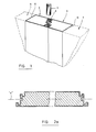
- Figure 1 is a perspective view of two panels joined in line according to a first mode of preferred embodiment of the invention, or a set of studs and mortises according to the invention is present on elements that are separate from the panels, but attached to the edges of these.
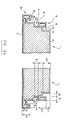
- Figures 2a and 2b are sectional views horizontal ends of a panel are the edges are integrally formed of a set of studs and mortises according to a second preferred embodiment of the invention.
- Figure 3 is a horizontal sectional view ends of two panels as shown in the Figure 2, having their respective sets of studs and mortises facing each other.
- Figure 4 is a horizontal sectional view similar to Figure 3, showing the panels once assembled and the key inserted.
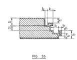
- Figures 5a and 5b are sectional views horizontal ends of a panel are the edges are integrally formed of a set of studs and mortises according to a third preferred embodiment of the invention.
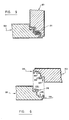
- Figure 6 is a horizontal sectional view ends of two panels as shown in the Figure 5, having their respective sets of studs and mortises facing each other so as to achieve an assembly of the panels in line.
- Figure 7 is a horizontal sectional view similar to Figure 5, showing the panels once assembled online and the key inserted.
- Figure 8 appearing on the same board of drawings that Figure 5a is a sectional view horizontal of the ends of two panels such as illustrated in FIG. 5, the respective sets of tenons and mortises are presented next to one of the other so as to assemble the panels at right angles.
- Figure 9 appearing on the same drawing board as Figure 6, is a sectional view horizontal of two panels as illustrated on the figure 5, once assembled at right angles and the key inserted.
- Figure 1 shows two panels 9 and 7 seals according to a first preferred embodiment of the assembly device according to the invention. It includes a element 3 nested with a second element 5 and a key 4 positioned to be inserted in a cavity 6 left between the two elements once they are nested.
- the elements 3 and 5 are provided with a set of pins mortises whose structure is identical to that which will be described below with reference to Figure 2.
- the elements 3 and 5 are separate from panels 9 and 7 and are fixed to the edges 15 and 13 thereof by any means suitable (glue, screws ).
- Figure 2 shows a sectional view of panels with sets of tenons and mortises according to a second embodiment of the invention where the games of pins are integrated into the panel.
- each panel 1 or 2 has a longitudinal axis "A", two opposite surfaces 8 and 10, and at least one edge 12 provided with a set of studs and mortises.
- Each edge 12 provided with pins and mortises includes a central groove 14 oriented in the "A" axis of the panel. This groove has two opposite sides and defines with the groove 12 of the adjacent edge, a cavity which corresponds to that numbered 6 in the mode of realization of figure 1.
- Each set of tenons and mortises includes a first rectangular post 16, which has a length L1 in the direction of axis "A" of the panel.
- This first tenon 16 is positioned on the side of one of the surfaces of the panel 8 relative to the axis "A". This first tenon 16 heads towards said surface but stops at a distance D1 of this one.
- This tenon 16 has a first side 18, which at least partly defines one of the opposite sides of the groove central 14.
- Each set of tenons and mortises includes also a first mortise 20, which has sides opposite, spaced a distance of length L2.
- This first mortise 20 is oriented outwards and opens on the same surface of panel 8 as the first tenon 16.
- This mortise 20 has one of its opposite sides which is defined, at least in part, by a second side 22 of the tenon 16, this second side 22 of tenon 16 being adjacent to the side 18 of the tenon 16.
- the mortise 20 has the other of its opposite sides of a depth D2, which is defined by a portion 24 of the edge 12 of the panel and which joins the panel surface 8.
- Each set of tenons and mortises includes also a second rectangular stud 26 which has sides and a length equal to L2 with respect to the axis "A" of the panel.
- This second tenon 26 is positioned on the side of the other surface 10 of the panel with respect to the axis "A”. This second tenon 26 goes towards the axis "A" of the panel.
- the side 29 of the second tenon 26 which is closest of axis "A" ' is positioned at a distance D2 from the surface 10 of the panel.
- the side of tenon 26, opposite the side 29 closest to axis "A" is tangent to the other surface 10 of the panel.
- each set of tenons and mortises in the assembly device according to the invention comprises a second mortise 28 which has opposite sides spaced one distance equal to L1.
- This second mortise 28 is open inwards and oriented towards the "A" axis of the sign.
- This mortise 28 is tangent to the groove 14 and has a bottom arranged at a distance D1 from the other surface 10 of the panel.
- This mortise 28 also has one of its sides opposites defined at least in part by a side 30 of the second tenon 26.
- This side 30 of the tenon 26 is adjacent to the side 29 closest to axis "A".
- the second mortise 28 has, in addition, the other of its opposite sides defined by another portion 32 of the edge 12 of the panel.
- Figure 3 shows the two panels 1 and 2 previously described, ready to be assembled. To this end, the panels are positioned relative to each other so as to allow an assembly of these into one movement.
- the tenons and mortises are shaped to allow the first tenon 16 of the edge 12 of the panel 1 to insert a single movement in the second mortise 128 of the edge adjacent 112 of the other panel 2.
- the second pin 26 of edge 12 of the same panel 1 is inserted of the same movement in the first mortise 120 of the adjacent edge 112 of the other panel 2.
- key 4 is inserted in the central cavity so as to block the device.
- a third preferred embodiment of the invention is shown in Figures 5 to 9.
- the panels are provided with a device with certain characteristics structural similar to the second embodiment. Also, for simplicity, the elements illustrated on Figures 5 to 9 have been numbered so that elements similar to those previously described are identified by numbers that differ only by the number of hundreds.
- This third embodiment has a structure which differs from the second mode of realization by the fact that the groove 214 has its sides which are equal to L2 and are separated from each other by a distance equal to L1.
- the first tenon 216 has a shape rectangular
- its second side 222 has a length equal to L2, as well as the opposite sides of the second mortise 228 which are also equal to L2.
- the second tenon 226 has its side 234, opposite to that 230 defining in part the second mortise 228, equal to L1.
- This tenon 226 has, moreover, its side 236 opposite to that most 229 close to axis "A", which is positioned at a distance L2 from the other surface 210 of the panel.
- This opposite side 236 of the second tenon 226 determines a corner 238 open on the other surface 210 of the panel.
- the distance L1 is equivalent to twice the distance L2, which implies that the section of the cavity is a square.
- this third embodiment preferred of the invention it is possible to join the online panels (see Figure 6 and 7). We then proceed in the same way as for the panels according to the first preferred embodiment of the invention.
- This third preferred embodiment also allows for perpendicular nesting of the panels. So the figure 8 represents the two panels of figure 5 arranged perpendicular to each other so as to be assembled in one movement. For proceed to nest the first tenon 216 of the edge of the panel 201 must engage in the groove central 314 of the adjacent edge of the other panel 302, while the second mortise 228 at the edge of the panel 201 receives the second tenon 326 from the adjacent edge of the other panel 302.
- Figure 9 shows the panels of the figure 8 once assembled perpendicularly, the key 204 is inserted into the cavity formed by the union of the central groove 214 of the panel 201 and of the second mortise 328 on the other panel 302.
- the games of tenons and mortises according to the invention do not integral part of the panels but are present on separate elements of the panels to be assembled, such as shown in Figure 1.
- the set of tenons and mortises present on the elements is analogous to that described in the second preferred embodiment of the invention.
- the elements distinct 3 and 4 are fixed on the edges of the panels 9 and 7.
- These elements 5 and 3 are provided with a set of studs and mortises according to the first preferred variant of the invention as shown in Figures 2, 3 and 4.
- the key, the panels, or the elements separate, with sets of tenons and mortises according to the invention can obviously be manufactured in any suitable building materials and in particular plastics, wood, metal and various materials composites etc .... They can be obtained by pultrusion, extrusion, molding, cutting or any other means usually known to those skilled in the art.
Landscapes
- Engineering & Computer Science (AREA)
- Architecture (AREA)
- General Engineering & Computer Science (AREA)
- Physics & Mathematics (AREA)
- Electromagnetism (AREA)
- Civil Engineering (AREA)
- Structural Engineering (AREA)
- Mechanical Engineering (AREA)
- Joining Of Building Structures In Genera (AREA)
Description
Claims (7)
- Un dispositif d'assemblage pour maintenir ensemble des panneaux par leurs arêtes, chaque panneau (1, 7) ayant un axe longitudinal (A) perpendiculaire à la liaison entre les deux panneaux, deux surfaces opposées (8, 10), et au moins une arête munie d'un jeu de tenons (16, 26) et de mortaises (20, 28) façonnés pour s'imbriquer d'un seul mouvement avec un jeu correspondant de tenons et de mortaises façonnés et disposés sur une arête adjacente d'un autre panneau (2, 9), lesdits panneaux une fois imbriqués pouvant être bloqués à l'aide d'une clef (4, 11) insérable dans une cavité (6) s'étendant centralement entre lesdites arêtes adjacentes et formée de rainures centrales (14) ayant deux côtés opposés et orientés dans l'axe longitudinal (A) de chaque panneau, ladite cavité ayant une section d'une surface sensiblement égale à deux fois la surface de la rainure d'un panneau, chaque jeu de tenons et de mortaises incluant :ledit dispositif d'assemblage étant caractérisé en ce que les côtés opposés de la rainure centrale (14) sont séparés l'un de l'autre par une distance égale à L1 correspondant à la longueur du premier tenon (16) ou à la distance des côtés opposés de la seconde mortaise (28) de manière à permettre une imbrication des panneaux par un seul mouvement dans le sens vertical par rapport à l'axe longitudinal (A) des panneaux, l'un desdits côtés opposés de la rainure centrale étant, au moins en partie, défini par un côté (18) du premier tenon (16).un premier tenon (16) parallélépipèdique, ayant une longueur L1 dans le sens de l'axe longitudinal (A) du panneau, positionné du côté d'une des surfaces (8) du panneau par rapport audit axe longitudinal et se dirigeant vers ladite surface mais s'arrêtant à une distance D1 de celle-ci,une première mortaise (20) orientée vers l'extérieur, ouvrant sur la même surface du panneau que le premier tenon (16) et ayant des côtés opposés espacés d'une distance de longueur L2, dont l'un est défini au moins en partie par un côté (22) du premier tenon, l'autre côté opposé, de profondeur D2, étant défini par une portion (24) de l'arête du panneau et rejoignant la surface (8) dudit panneau,un second tenon (26) parallélépipèdique ayant des côtés et une longueur égale à L2 par rapport à l'axe longitudinal (A) du panneau, ce second tenon étant positionné du côté de l'autre surface (10) du panneau par rapport audit axe longitudinal et se dirigeant vers l'axe longitudinal du panneau, le côté (29) dudit second tenon se trouvant le plus proche dudit axe longitudinal étant positionné à une distance D2 de ladite autre surface (10) du panneau,une seconde mortaise (28), ayant des côtés opposés espacés d'une distance égale à L1 et étant ouverte vers l'intérieur et orientée vers l'axe longitudinal (A) du panneau, cette seconde mortaise ayant un fond disposé à une distance D1 de l'autre surface (10) du panneau et ayant aussi un de ses côtés opposés défini au moins en partie par un côté (30) du second tenon (26), ce côté du second tenon étant adjacent au côté de ce second tenon le plus proche de l'axe longitudinal,
- Dispositif d'assemblage selon la revendication 1 caractérisé en ce que le côté du second tenon (26), opposé au côté (29) le plus proche de l'axe longitudinal (A), est tangent à l'autre surface (10) du panneau.
- Dispositif d'assemblage selon la revendication 1 caractérisé en ce que la rainure centrale (14) a ses côtés opposés égaux à L2, le second côté (22/222) du premier tenon (16/216) ayant une longueur égale à L2, la seconde mortaise (28/228) ayant ses côtés opposés égaux à L2, et le second tenon (16/226) ayant son côté (34/234) opposé à celui définissant en partie la seconde mortaise qui est égal à L1 et son côté opposé à celui le plus proche de l'axe longitudinal, qui est positionné à une distance L2 de l'autre surface (10/210) du panneau, ce dit côté opposé du second tenon déterminant une encoignure (38/238) ouverte sur ladite autre surface (10/210) du panneau, la distance D1 étant égale à la somme des distances L1 et L2, ce dispositif particulier permettant non seulement une imbrication des panneaux en ligne par un seul mouvement dans le sens vertical par rapport à l'axe longitudinal (A) des panneaux (1/201, 2/302), mais aussi une imbrication de ces mêmes panneaux dans des directions transversales par un seul mouvement selon lequel le premier tenon (16/216) de l'arête du panneau (1/201) s'engage dans la rainure centrale (14/314) de l'arête adjacente de l'autre panneau (2/302), tandis que la seconde mortaise (28/228) de l'arête du panneau reçoit le second tenon (26/326) de l'arête adjacente de l'autre panneau, avant insertion de la clef (11/211).
- Dispositif d'assemblage selon la revendication 3 caractérisé en ce que la distance L1 est équivalente à deux fois la distance L2, ce qui implique que la section de la cavité (6) est un losange.
- Dispositif d'assemblage selon les revendications 1, 2, 3 ou 4 caractérisé en ce que la forme parallélépipèdique du premier (16) et du second tenon (26) est rectangulaire.
- Dispositif d'assemblage selon les revendications 1, 2, 3, 4 ou 5 caractérisé en ce que le jeu de tenons (16, 26) et mortaises (20, 28) est intégré à l'arête correspondante du panneau.
- Dispositif d'assemblage selon les revendications 1, 2, 3, 4 ou 5 caractérisé en ce que le jeu de tenons (16, 26) et mortaises (20, 28) est intégré à un élément (3, 5) distinct du panneau, ledit élément étant destiné à venir se fixer sur les arêtes correspondantes dudit panneau.
Applications Claiming Priority (3)
| Application Number | Priority Date | Filing Date | Title |
|---|---|---|---|
| CA2114280 | 1994-01-26 | ||
| CA 2114280 CA2114280A1 (fr) | 1994-01-26 | 1994-01-26 | Dispositif d'assemblage pour maintenir ensemble des panneaux par leurs aretes |
| PCT/FR1995/000079 WO1995020725A1 (fr) | 1994-01-26 | 1995-01-25 | Dispositif d'assemblage pour maintenir ensemble des panneaux par leurs aretes |
Publications (2)
| Publication Number | Publication Date |
|---|---|
| EP0835387A1 EP0835387A1 (fr) | 1998-04-15 |
| EP0835387B1 true EP0835387B1 (fr) | 1999-10-20 |
Family
ID=4152797
Family Applications (1)
| Application Number | Title | Priority Date | Filing Date |
|---|---|---|---|
| EP95907696A Expired - Lifetime EP0835387B1 (fr) | 1994-01-26 | 1995-01-25 | Dispositif d'assemblage pour maintenir ensemble des panneaux par leurs aretes |
Country Status (4)
| Country | Link |
|---|---|
| EP (1) | EP0835387B1 (fr) |
| CA (1) | CA2114280A1 (fr) |
| DE (1) | DE69512941D1 (fr) |
| WO (1) | WO1995020725A1 (fr) |
Families Citing this family (3)
| Publication number | Priority date | Publication date | Assignee | Title |
|---|---|---|---|---|
| FI990281A7 (fi) * | 1998-04-23 | 1999-10-24 | Heikki Haapiainen | Liitos erityisesti rakenne-elementtejä varten ja rakenne-elementti |
| DE20200664U1 (de) * | 2002-01-17 | 2002-07-25 | Kahl, Helmut, 32457 Porta Westfalica | Laserschutzwand |
| NL1037465C2 (nl) * | 2009-11-11 | 2011-05-18 | Maarten Martines Johannes Josephes Wijnen | Samenstel van bevestigingsmiddelen, bevestigingsdelen voor gebruik in een dergelijk samenstel en werkwijze. |
Family Cites Families (3)
| Publication number | Priority date | Publication date | Assignee | Title |
|---|---|---|---|---|
| DE1459718C3 (de) * | 1964-09-16 | 1974-12-12 | Harvey Aluminium (Inc.), Torrance, Calif. (V.St.A.) | Metallplanke für den Bodenbelag und Bodenbelag einer Start- und Landebahn |
| US3487756A (en) * | 1968-03-06 | 1970-01-06 | Dow Chemical Co | Structural unit |
| DE8519383U1 (de) * | 1985-07-04 | 1989-02-16 | Vereinigte Aluminium-Werke AG, 1000 Berlin und 5300 Bonn | Verbundprofil aus mindestens zwei Einzelprofilen |
-
1994
- 1994-01-26 CA CA 2114280 patent/CA2114280A1/fr not_active Abandoned
-
1995
- 1995-01-25 EP EP95907696A patent/EP0835387B1/fr not_active Expired - Lifetime
- 1995-01-25 WO PCT/FR1995/000079 patent/WO1995020725A1/fr not_active Ceased
- 1995-01-25 DE DE69512941T patent/DE69512941D1/de not_active Expired - Lifetime
Also Published As
| Publication number | Publication date |
|---|---|
| EP0835387A1 (fr) | 1998-04-15 |
| CA2114280A1 (fr) | 1995-07-27 |
| WO1995020725A1 (fr) | 1995-08-03 |
| DE69512941D1 (de) | 1999-11-25 |
Similar Documents
| Publication | Publication Date | Title |
|---|---|---|
| EP1440214B1 (fr) | Dispositif d'assemblage des bords de panneaux | |
| WO2015155430A1 (fr) | Systeme d'assemblage de panneaux suivant un diedre pour realiser un meuble et meuble ainsi realise | |
| FR2781513A1 (fr) | Element de surface du genre dalle, panneau pour sol, mur, toiture par exemple | |
| EP1282753A1 (fr) | Dispositif d'assemblage des bords longitudinaux de panneaux, lattes ou lambris, a repartition de forces | |
| FR2826391A1 (fr) | Dispositif d'assemblage des bords de panneaux, lattes ou lambris | |
| CA2200677C (fr) | Systeme d'assemblage de panneaux prefabriques pour la realisation d'une cloison de piscine et cloison de piscine ainsi obtenue | |
| EP2191081B1 (fr) | Elements PREFABRIQUES DE CONSTRUCTION EN BOIS ET SYSTEME CONSTRUCTIF | |
| EP0975843B1 (fr) | Paroi de construction avec dispositif d'assemblage des planches de bois constitutives de la paroi | |
| EP1595041B1 (fr) | Piscine modulaire | |
| EP0835387A1 (fr) | Dispositif d'assemblage pour maintenir ensemble des panneaux par leurs aretes | |
| EP1404933A1 (fr) | Dispositif d'assemblabe de panneau, lattes ou lambris, a repartition de forces | |
| FR2808824A1 (fr) | Dispositif d'assemblage des bords longitudinaux de panneaux, lattes ou lambris, a repartition de forces | |
| FR2773566A1 (fr) | Element de construction destine a la construction d'une paroi anti-bruit, realise dans un materiau du type beton ou analogue | |
| FR2807080A1 (fr) | Coffrage isolant aplatissable pour la realisation d'un mur en beton | |
| EP0175196B1 (fr) | Elément de construction, système de construction avec un montant pour l'assemblage sur au moins un tel élément et construction démontable réalisée par assemblage d'une pluralité de ces éléments et montants | |
| CA2405928A1 (fr) | Dispositif d'assemblage des bords longitudinaux de panneaux, lattes ou lambris | |
| FR2808997A1 (fr) | Dispositif et procede d'assemblage de panneaux de cercueils, et cercueils obtenus par leur mise en oeuvre | |
| EP1185745B1 (fr) | Agencement de poutres comprenant un element de liaison pour habitation | |
| FR2826392A1 (fr) | Dispositif d'assemblage des bords de panneaux, lattes ou lambris | |
| FR2795110A1 (fr) | Coffrage isolant pour la realisation d'un mur en beton | |
| FR2720425A1 (fr) | Dispositif d'assemblage de deux éléments de construction, pièces d'assemblage et éléments de construction conçu pour la réalisation de ce dispositif d'assemblage. | |
| FR2796406A1 (fr) | Coffrage permanent isolant pour la realisation d'un mur en beton | |
| FR2715959A1 (fr) | Poutre de support de panneaux de coffrage et structure de coffrage comportant de telles poutres. | |
| FR2732992A3 (fr) | Plancher temporaire, en particulier pour expositions, forme de modules constitues de supports et d'elements de recouvrement | |
| FR3099505A1 (fr) | Utilisation d’au moins un élément composite pour réaliser un revêtement de surface extérieur de type terrasse |
Legal Events
| Date | Code | Title | Description |
|---|---|---|---|
| PUAI | Public reference made under article 153(3) epc to a published international application that has entered the european phase |
Free format text: ORIGINAL CODE: 0009012 |
|
| 17P | Request for examination filed |
Effective date: 19960820 |
|
| AK | Designated contracting states |
Kind code of ref document: A1 Designated state(s): DE FR GB |
|
| 17Q | First examination report despatched |
Effective date: 19980917 |
|
| GRAG | Despatch of communication of intention to grant |
Free format text: ORIGINAL CODE: EPIDOS AGRA |
|
| GRAG | Despatch of communication of intention to grant |
Free format text: ORIGINAL CODE: EPIDOS AGRA |
|
| GRAH | Despatch of communication of intention to grant a patent |
Free format text: ORIGINAL CODE: EPIDOS IGRA |
|
| GRAH | Despatch of communication of intention to grant a patent |
Free format text: ORIGINAL CODE: EPIDOS IGRA |
|
| GRAA | (expected) grant |
Free format text: ORIGINAL CODE: 0009210 |
|
| AK | Designated contracting states |
Kind code of ref document: B1 Designated state(s): DE FR GB |
|
| PG25 | Lapsed in a contracting state [announced via postgrant information from national office to epo] |
Ref country code: GB Free format text: LAPSE BECAUSE OF FAILURE TO SUBMIT A TRANSLATION OF THE DESCRIPTION OR TO PAY THE FEE WITHIN THE PRESCRIBED TIME-LIMIT Effective date: 19991020 |
|
| REF | Corresponds to: |
Ref document number: 69512941 Country of ref document: DE Date of ref document: 19991125 |
|
| PG25 | Lapsed in a contracting state [announced via postgrant information from national office to epo] |
Ref country code: DE Free format text: LAPSE BECAUSE OF FAILURE TO SUBMIT A TRANSLATION OF THE DESCRIPTION OR TO PAY THE FEE WITHIN THE PRESCRIBED TIME-LIMIT Effective date: 20000121 |
|
| PGFP | Annual fee paid to national office [announced via postgrant information from national office to epo] |
Ref country code: FR Payment date: 20000207 Year of fee payment: 6 |
|
| GBV | Gb: ep patent (uk) treated as always having been void in accordance with gb section 77(7)/1977 [no translation filed] |
Effective date: 19991020 |
|
| PLBE | No opposition filed within time limit |
Free format text: ORIGINAL CODE: 0009261 |
|
| STAA | Information on the status of an ep patent application or granted ep patent |
Free format text: STATUS: NO OPPOSITION FILED WITHIN TIME LIMIT |
|
| 26N | No opposition filed | ||
| PG25 | Lapsed in a contracting state [announced via postgrant information from national office to epo] |
Ref country code: FR Free format text: LAPSE BECAUSE OF NON-PAYMENT OF DUE FEES Effective date: 20020930 |
|
| REG | Reference to a national code |
Ref country code: FR Ref legal event code: ST |
|
| PG25 | Lapsed in a contracting state [announced via postgrant information from national office to epo] |
Ref country code: FR Free format text: LAPSE BECAUSE OF NON-PAYMENT OF DUE FEES Effective date: 20010131 |