EP0835407B1 - Dispositif d'eclairage localise - Google Patents
Dispositif d'eclairage localise Download PDFInfo
- Publication number
- EP0835407B1 EP0835407B1 EP96908818A EP96908818A EP0835407B1 EP 0835407 B1 EP0835407 B1 EP 0835407B1 EP 96908818 A EP96908818 A EP 96908818A EP 96908818 A EP96908818 A EP 96908818A EP 0835407 B1 EP0835407 B1 EP 0835407B1
- Authority
- EP
- European Patent Office
- Prior art keywords
- light
- plane
- icon
- illumination apparatus
- light pipe
- Prior art date
- Legal status (The legal status is an assumption and is not a legal conclusion. Google has not performed a legal analysis and makes no representation as to the accuracy of the status listed.)
- Expired - Lifetime
Links
Images


Classifications
-
- F—MECHANICAL ENGINEERING; LIGHTING; HEATING; WEAPONS; BLASTING
- F21—LIGHTING
- F21V—FUNCTIONAL FEATURES OR DETAILS OF LIGHTING DEVICES OR SYSTEMS THEREOF; STRUCTURAL COMBINATIONS OF LIGHTING DEVICES WITH OTHER ARTICLES, NOT OTHERWISE PROVIDED FOR
- F21V5/00—Refractors for light sources
- F21V5/02—Refractors for light sources of prismatic shape
-
- B—PERFORMING OPERATIONS; TRANSPORTING
- B60—VEHICLES IN GENERAL
- B60Q—ARRANGEMENT OF SIGNALLING OR LIGHTING DEVICES, THE MOUNTING OR SUPPORTING THEREOF OR CIRCUITS THEREFOR, FOR VEHICLES IN GENERAL
- B60Q3/00—Arrangement of lighting devices for vehicle interiors; Lighting devices specially adapted for vehicle interiors
- B60Q3/10—Arrangement of lighting devices for vehicle interiors; Lighting devices specially adapted for vehicle interiors for dashboards
- B60Q3/14—Arrangement of lighting devices for vehicle interiors; Lighting devices specially adapted for vehicle interiors for dashboards lighting through the surface to be illuminated
-
- B—PERFORMING OPERATIONS; TRANSPORTING
- B60—VEHICLES IN GENERAL
- B60Q—ARRANGEMENT OF SIGNALLING OR LIGHTING DEVICES, THE MOUNTING OR SUPPORTING THEREOF OR CIRCUITS THEREFOR, FOR VEHICLES IN GENERAL
- B60Q3/00—Arrangement of lighting devices for vehicle interiors; Lighting devices specially adapted for vehicle interiors
- B60Q3/10—Arrangement of lighting devices for vehicle interiors; Lighting devices specially adapted for vehicle interiors for dashboards
- B60Q3/16—Circuits; Control arrangements
-
- B—PERFORMING OPERATIONS; TRANSPORTING
- B60—VEHICLES IN GENERAL
- B60Q—ARRANGEMENT OF SIGNALLING OR LIGHTING DEVICES, THE MOUNTING OR SUPPORTING THEREOF OR CIRCUITS THEREFOR, FOR VEHICLES IN GENERAL
- B60Q3/00—Arrangement of lighting devices for vehicle interiors; Lighting devices specially adapted for vehicle interiors
- B60Q3/60—Arrangement of lighting devices for vehicle interiors; Lighting devices specially adapted for vehicle interiors characterised by optical aspects
- B60Q3/62—Arrangement of lighting devices for vehicle interiors; Lighting devices specially adapted for vehicle interiors characterised by optical aspects using light guides
- B60Q3/64—Arrangement of lighting devices for vehicle interiors; Lighting devices specially adapted for vehicle interiors characterised by optical aspects using light guides for a single lighting device
-
- B—PERFORMING OPERATIONS; TRANSPORTING
- B60—VEHICLES IN GENERAL
- B60Q—ARRANGEMENT OF SIGNALLING OR LIGHTING DEVICES, THE MOUNTING OR SUPPORTING THEREOF OR CIRCUITS THEREFOR, FOR VEHICLES IN GENERAL
- B60Q3/00—Arrangement of lighting devices for vehicle interiors; Lighting devices specially adapted for vehicle interiors
- B60Q3/60—Arrangement of lighting devices for vehicle interiors; Lighting devices specially adapted for vehicle interiors characterised by optical aspects
- B60Q3/68—Arrangement of lighting devices for vehicle interiors; Lighting devices specially adapted for vehicle interiors characterised by optical aspects using ultraviolet light
-
- F—MECHANICAL ENGINEERING; LIGHTING; HEATING; WEAPONS; BLASTING
- F21—LIGHTING
- F21V—FUNCTIONAL FEATURES OR DETAILS OF LIGHTING DEVICES OR SYSTEMS THEREOF; STRUCTURAL COMBINATIONS OF LIGHTING DEVICES WITH OTHER ARTICLES, NOT OTHERWISE PROVIDED FOR
- F21V7/00—Reflectors for light sources
- F21V7/0091—Reflectors for light sources using total internal reflection
-
- G—PHYSICS
- G02—OPTICS
- G02B—OPTICAL ELEMENTS, SYSTEMS OR APPARATUS
- G02B6/00—Light guides; Structural details of arrangements comprising light guides and other optical elements, e.g. couplings
- G02B6/0001—Light guides; Structural details of arrangements comprising light guides and other optical elements, e.g. couplings specially adapted for lighting devices or systems
- G02B6/0005—Light guides; Structural details of arrangements comprising light guides and other optical elements, e.g. couplings specially adapted for lighting devices or systems the light guides being of the fibre type
- G02B6/0006—Coupling light into the fibre
-
- G—PHYSICS
- G02—OPTICS
- G02B—OPTICAL ELEMENTS, SYSTEMS OR APPARATUS
- G02B6/00—Light guides; Structural details of arrangements comprising light guides and other optical elements, e.g. couplings
- G02B6/0001—Light guides; Structural details of arrangements comprising light guides and other optical elements, e.g. couplings specially adapted for lighting devices or systems
- G02B6/0096—Light guides; Structural details of arrangements comprising light guides and other optical elements, e.g. couplings specially adapted for lighting devices or systems the lights guides being of the hollow type
-
- G—PHYSICS
- G02—OPTICS
- G02B—OPTICAL ELEMENTS, SYSTEMS OR APPARATUS
- G02B6/00—Light guides; Structural details of arrangements comprising light guides and other optical elements, e.g. couplings
- G02B6/24—Coupling light guides
- G02B6/42—Coupling light guides with opto-electronic elements
- G02B6/4298—Coupling light guides with opto-electronic elements coupling with non-coherent light sources and/or radiation detectors, e.g. lamps, incandescent bulbs, scintillation chambers
-
- F—MECHANICAL ENGINEERING; LIGHTING; HEATING; WEAPONS; BLASTING
- F21—LIGHTING
- F21W—INDEXING SCHEME ASSOCIATED WITH SUBCLASSES F21K, F21L, F21S and F21V, RELATING TO USES OR APPLICATIONS OF LIGHTING DEVICES OR SYSTEMS
- F21W2111/00—Use or application of lighting devices or systems for signalling, marking or indicating, not provided for in codes F21W2102/00 – F21W2107/00
-
- F—MECHANICAL ENGINEERING; LIGHTING; HEATING; WEAPONS; BLASTING
- F21—LIGHTING
- F21Y—INDEXING SCHEME ASSOCIATED WITH SUBCLASSES F21K, F21L, F21S and F21V, RELATING TO THE FORM OR THE KIND OF THE LIGHT SOURCES OR OF THE COLOUR OF THE LIGHT EMITTED
- F21Y2115/00—Light-generating elements of semiconductor light sources
- F21Y2115/10—Light-emitting diodes [LED]
-
- Y—GENERAL TAGGING OF NEW TECHNOLOGICAL DEVELOPMENTS; GENERAL TAGGING OF CROSS-SECTIONAL TECHNOLOGIES SPANNING OVER SEVERAL SECTIONS OF THE IPC; TECHNICAL SUBJECTS COVERED BY FORMER USPC CROSS-REFERENCE ART COLLECTIONS [XRACs] AND DIGESTS
- Y10—TECHNICAL SUBJECTS COVERED BY FORMER USPC
- Y10S—TECHNICAL SUBJECTS COVERED BY FORMER USPC CROSS-REFERENCE ART COLLECTIONS [XRACs] AND DIGESTS
- Y10S362/00—Illumination
- Y10S362/80—Light emitting diode
Definitions
- This invention relates to illumination apparatus according to the preamble of claim 1.
- Such an illumination apparatus is disclosed in US-A-4,767,172.
- This document describes a light collector for a LED array in which the light beam is shaped by a convex lens portion and a parabolic reflecting surface portion of the collector so as to efficiently collect and collimate light emitted by the LED into two concentric collimated beams.
- the collimated light beams are reflected from a reflector surface into a light pipe, and are then used to discharge edge portions or pitch portions on a photoreceptor surface during an electrophotographic process.
- Localized illumination is used in a variety of applications in which numbers, shapes, designs, icons, or other figures are to be illuminated against a background of relatively darker shade.
- Examples of localized illumination applications include lighting icons on computer screens, cameras, video cameras, stereos, household appliances, and various industrial uses, among many others.
- a particular application of localized illumination is in automobile dashboard lighting.
- a typical automobile dashboard contains a variety of discrete elements that may be illuminated for observation by someone within the vehicle. Elements that might be illuminated include, for example, icons of gas pumps, oil cans, persons in seatbealts, or messages such as "check engine”, “check oil”, and "fasten safety belt”. Individual elements of digits in a digital display of speed, revolutions per minute, miles per gallon, or gallons in gas tank also require localized lighting.
- One alternative to a conventional automobile dashborad is a "heads-up" display in which an icon is reflected off the inside of a winshield using vacuum florescent displays. Such displays also use localized illumination, but, require extremely high power.
- Localized illumination for automobile dashboard lighting is commonly accomplished using ordinary lamps situated in wells formed in the dashboard base structure.
- lamps can be selected that emit light in a forward direction (that is, from the light source toward the plane of the object to be illuminated), there is always some light emitted laterally.
- the laterally-emitted light of a lamp may combine with the laterally-emitted light of adjacent lamps, thereby creating areas of increased light, or light "hot spots," within the dashboard enclosure.
- Such hot spots are undesirable because of the uneven illumination that may result and, more commonly, because they reduce illumination efficiency.
- the quality of the light generated by such dashboard lamps is diminished because much of the light that is generated is wasted by being emitted in a lateral direction.
- the forwardly-emitted light is not efficiently produced.
- LED chips are also used as the light source in dashboard lighting applications.
- the energy emitted from LEDs tends to be low, and because light from LED chips is usually emitted in four directions, the problem of inefficient light generation is even more of a concern with LEDs than with ordinary lamps. It is particularly difficult to get enough output from the LEDs to be clearly visible through black dashboard covers that are currently popular in the automotive industry. Individual LED chips are not bright enough to illuminate a desired area through such dashboard covers, particularly when "heads-up" displays are used.
- No known device satisfactorily provides the efficient generation of sufficiently bright light for use in localized illumination in applications, such as, automobile dashboard lighting.
- the present invention provides illumination apparatus comprising: Illumination apparatus, comprising
- the illumination apparatus maximizes the brightness of an object, such as an icon, digit, or other figure, requiring localized illumination by collecting, redirecting, and channeling all or most of the light from a light source to a single plane at or proximate the icon,-digit, or figure.
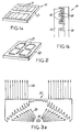
- Figure 1 shows an exemplary circuit board 10, with electrical connecting lines 11 formed thereon, used in an illumination apparatus constructed in accordance with the present invention.
- Electrical connecting lines 11 are formed in any desired pattern and in a conventional manner on circuit board 10.
- electrical connecting lines 11 are arranged to supply power for a digital display.
- the light source for the display are LEDs although conventional lamps may also be used.
- Surface 12 of circuit board 10 is layered with the maximum amount of metal, or other reflective material, possible in order to provide maximum reflection of LED light off circuit board 10. This is done so that the light reflected off surface 12 can be gathered and redirected in the forward direction. Surface 12 acts like a mirror in this respect.
- FIG. 1b shows an exemplary LED arrangement 15.
- LED arrangement 15 is adapted to be mounted on circuit board 10 in the desired pattern.
- a plurality of LEDs 16 are mounted on a common D/A (i.e., die attached) pad 17 and connected by wires 18 to common wire bond pad 19.
- the LEDs 16 may also be mounted on individual pads 17 on the board 10 and also connected by wires 18 to individual wire bond pads 19.
- Figure 2 shows an exemplary digital display housing 20 adapted to be mounted over LED arrangement 15 on circuit board 10.
- Digital display housing 20 has placement apertures 21 formed therethrough.
- Digital display housing 20, LED arrangement 15, and circuit board 10 are assembled such that placement apertures 21 are located directly above LEDs 16 on circuit board 10.
- One or more LEDs 16 may be accessible through a single placement aperture 21.
- FIG. 3a is a side view of an exemplary TIR lens 25.
- Light beams 26 emitted laterally from LED 16, over which lens 25 is placed, are redirected vertically by lens 25 according to known principles of TIR lenses.
- U.S. Patent No. 5,404,869, issued to Parkyn, Jr. et al. provides a discussion of the principles involved with TIR lenses, and describes a device suitable for use in the present invention.
- the '869 patent is incorporated herein by reference for its teachings on TIR lenses and its description of exemplary devices.
- TIR lens 25 is first placed inside a light pipe, and the light pipe is then mounted over LED 16.
- Figure 3b show an exemplary light pipe 30 that has a tapered bottom section 31 that terminates in bottom end 32 and a top 33.
- Light pipe 30 is designed to fit into placement aperture 21 and over at least one LED 16.
- Lens 25 is mounted within light pipe 30 as shown in Figures 4a and 4b.
- light pipe 30 is hollow and open at both bottom end 32 and top 33.
- Light pipe 30 is formed of a transparent material such as polycarbonate or acrylic. Temperature tolerant materials should be used for light pipe 30 in applications where temperature extremes are expected.
- the dimensions of light pipe 30, and TIR lens 25 within it are determined by the location of LEDs 16 on circuit board 10 under digital display housing 20 and by certain mechanical restraints.
- the mechanical constraints include, for example, the height from the surface of circuit board 10 to the top of placement aperture 21, the desired shape of the illuminated area, and the allowable width of placement aperture 21.
- This and other data, such as indices of refraction, are used to obtain (for example, via computer-aided calculation and analysis) the desired overall TIR design according to methods known in the art as described in U.S. Patent No. 5,404,86, which has been incorporated herein by reference.
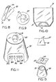
- Figure 5 is a cross-sectional front view of light pipe 30 having TIR lens 25 mounted therein and being placed in position over LED 16.
- Figure 6 is a cross-sectional side view of light pipe 30 and TIR lens 25 over LED 16.
- light beams 26 emitted laterally from LED 16 are redirected vertically by TIR lens 25.
- Light beams such as beam 27 emitted vertically from LED 16 pass through TIR lens 25 without directional change.
- Beams such as beam 28 that are emitted down from LED 16 are reflected off surface 12 of circuit board 10, which is metallized to act as a mirror. Reflected beam 28 then strikes TIR lens 25, in effect, as a laterally emitted beam from LED 16. Beam 28 is then redirected vertically with the other beams 26, 27. In this manner, light from LED 16 is maximized at the plane defined by top 33 of light pipe 30.
- the individual bars or elements of the digits in display housing 20, represented by placement apertures 21, are illuminated brightly enough for automobile dashboard applications. Each LED 16 in each placement aperture 21 may be turned on and off individually as desired.
- light pipe 30 may be configured so as to have a constricting or tapered shape.
- light pipe 30 is conical with bottom end 32 having the largest diameter.
- TIR lens 25 is disposed at the bottom of light pipe 30 where it gathers the output from LED 16 and redirects it up through light pipe 30. Because of the taper in light pipe 30, all of the light is then channeled to a smaller diameter plane at top 33.
- the brightness of the light at the plane at top 33 is higher than if light pipe 30 were not tapered and top 33 had the same diameter as bottom end 32. More light is emitted per unit area in such a design.
- Figure 8 shows a tapered structure for light pipe 30 in a pie-shaped design.
- LED 16 and TIR lens 25 are contained in bottom section 31 of light pipe 30.
- Light pipe 30 has the largest horizontal cross-sectional plane at bottom end 32 and tapers to its narrowest cross section at top 33. As in Figure 7, the LED light is collected and redirected by TIR lens 25 and then channeled to a smaller diameter plane at top 33, where the light is effectively brighter.
- FIG. 9 illustrates an exemplary cover 40 adapted to be disposed over top 33 of light pipe 30.
- Cover 40 may be shaped to match the shape of top 33 and may be integrally molded to top 33. Cover 40 may also be a film placed over top 33. Further, cover 40 may be integrally formed as part of light pipe 30 so that light pipe 30 is hollow but closed at top 33.
- Cover 40 has an icon 41 configured therein.
- Icon 41 will be illuminated to convey information to a viewer.
- icon 41 is a gas pump for use in an automobile dashboard display.
- the driver of an automobile may be alerted of a low tank of gas when icon 41 illuminates.
- Cover 40 may be constructed of the same material as light pipe 30, with icon 41 cut or stamped out of cover 40. Alternatively, cover 40 may be molded with icon 41 therein. Cover 40 may also be tapered to a raised plane in which icon 41 is configured. When illuminated, light emitted from LED 16 is collected by TIR lens 25 and directed through light pipe 30, which channels the light to the plane at cover 40 over top 33. All of the LED light is emitted through icon 41, creating a bright, visible feature.
- a plurality of LEDs 16 may be placed within a single light pipe 30. As shown in Figure 10, six LEDs 16 are disposed under TIR lens 25 within light pipe 30. LEDs 16 may be all of the same color, creating added brightness by the plural number of light sources. Alternatively, some or all of LEDs 16 may be of different colors, to be illuminated separately or in combination to create different colors for illumination.
- icon 41 of a gas tank in cover 40 atop light pipe 30 may be illuminated with green light from the LEDs when the gas tank is full.
- Circuit board 10 may be programmed or controlled to illuminate only green LEDs 16a and 16b.
- yellow LEDs 16c and 16d may be illuminated such that the driver sees a change in the color of icon 41 from green to yellow.
- red LEDs 16e and 16f may be illuminated such that the icon changes to red.
- only red and green LEDs 16a, 16b, 16e, and 16f may be used, all of which can be activated to shine in combination to create a yellow color for icon 41 at the desired time. This combined use of colored light from the LEDs may avoid excess material and energy use, eliminating the need for separate colored LEDs such as yellow LEDs 16c and 16d.
- the multicolor LEDs 16 may also be used with the digital display housing 20 discussed above. So, for example, in an automobile dashboard application, the multicolor LEDs 16 can be used to illuminate a digital display of the car speed, e.g., green below 55 miles per hour (mph), yellow between 55 and 65 mph, and red above 65 mph.
- FIG. 12 shows an exemplary illumination apparatus with light pipe 30 mounted in an automobile dashboard 61. Icon 41 becomes visible when LEDs 16 (not shown) beneath light pipe 30 are illuminated.
- Figure 13 illustrates another way of illuminating icon 41 using the present invention.
- the figure shows that an entirely separate piece 45 with icon 41 configured therein may be used, instead of cover 40, in combination with light pipe 30.
- light pipe 30 acts as a backlight, maximizing the light at the plane at top 33 for illumination of icon 41.
- Separate piece 45 is spaced apart from light pipe 30 and may be a part integral to the display structure itself, such as an automobile dashboard, with light pipe 30 illuminating it from behind.
- Figures 14 and 15 show an alternative illumination apparatus wherein a lens 50 is disposed over top 33 of light pipe 30.
- Lens 50 may further narrow the plane in which light from LEDs 16 are concentrated, thus enhancing the brightness of light at that plane.
- Lens 50 may be a simple cylindrical lens or a flat holographic lens. In the latter case, the holographic lens is used to narrow the field of view instead of as a diffuser to spread out the field of view.
- lens 50 in combination with light pipe 30 is particularly applicable to situations in which the field of view is well-defined. For example, in an automobile, because the driver's eyes must be below the roof of the car and above the steering wheel, there is a predefined area in which the image may be focused. By narrowing the plane of focus to this defined area, it is possible to further brighten an illuminated icon 41.
- Figure 16 illustrates use of lens 50 on light pipe 30 to focus light at the plane at which a separated icon 41 is located.
- icon 41 may be formed on a cover 40 of light pipe 30 beneath lens 50, such that the image of icon 41 is focused to the desired plane.
- FIG 17 shows an automobile dashboard using localized illumination. Icons 41 are visible through a black dashboard cover/panel 61 because of the added brightness contributed by illumination apparatus of the present invention.
- the illumination apparatus of the present invention is not used to image LED 16. Similarly, the light from LED 16 is not projected. Rather, the light from LED 16 is collected and directed to a single plane to maximize the output of LED 16 in automotive dashboard lighting and other applications.
- embodiments discussed herein pertain to use in an automobile dashboard
- embodiments of the invention useful in other applications such as traffic lights, computers, cameras, video cameras, stereos, and household appliances, are considered to be within the scope of the invention.
- light pipe 30 may be hollow with a closed top 33 and used in combination with lens 50, cover 40 and/or separate piece 45.
- the light emitted by the light source can include radiation having wavelengths outside the visible light spectrum, such as, infrared and ultraviolet.
- the increased visibility of an object to be viewed can be accomplished via a different physical reaction, e.g. incandescence, fluorescence, etc.
Landscapes
- Engineering & Computer Science (AREA)
- Physics & Mathematics (AREA)
- Mechanical Engineering (AREA)
- General Physics & Mathematics (AREA)
- Optics & Photonics (AREA)
- General Engineering & Computer Science (AREA)
- Arrangements Of Lighting Devices For Vehicle Interiors, Mounting And Supporting Thereof, Circuits Therefore (AREA)
- Led Device Packages (AREA)
- Instrument Panels (AREA)
- Illuminated Signs And Luminous Advertising (AREA)
Abstract
Claims (21)
- Dispositif d'éclairage comportant(a) une source lumineuse (16) au moins partiellement disposée dans un premier plan (12),(b) un élément optique (25) disposé au-dessus de la source lumineuse (16) pour collecter et diriger la lumière émise par la source lumineuse (16) dans une seule direction,(c) un moyen pour canaliser la lumière à travers un second plan différent du premier plan (12),
caractérisé en ce que(d) le premier plan (12) est muni d'une couche de matière réfléchissante pour assurer une réflexion maximale de la source lumineuse (16),(e) l'élément optique (25) est un élément optique à réflexion interne totale (élément TIR) disposé pour collecter et diriger toute la lumière émise par la source lumineuse (16) y compris la lumière latérale émise par cette source lumineuse (16),(f) le moyen est un conduit de lumière (30) distinct et dans lequel est monté l'élément optique à réflexion interne totale (25). - Dispositif d'éclairage selon la revendication 1,
caractérisé en ce que
la source lumineuse (16) est une diode photo-émissive. - Dispositif d'éclairage selon la revendication 1,
caractérisé en ce que
la source lumineuse (16) se compose de plusieurs diodes photo-émissives. - Dispositif d'éclairage selon la revendication 3,
caractérisé en ce qu'
au moins certaines des diodes photo-émissives ont des couleurs différentes l'une de l'autre. - Dispositif d'éclairage selon la revendication 1,
caractérisé en ce que
la conduite de lumière (30) a une forme conique. - Dispositif d'éclairage selon la revendication 1,
caractérisé en ce que
la conduite de lumière (30) est configurée pour que sa plus grande section se trouve à l'extrémité de la conduite de lumière (30), dans le premier plan (12) et que la section la plus étroite se trouve à l'extrémité de la conduite (30) située dans le second plan. - Dispositif d'éclairage selon la revendication 1,
caractérisé par
un couvercle (40) au moins partiellement translucide dans le second plan par-dessus la conduite de lumière (30). - Dispositif d'éclairage selon la revendication 7,
caractérisé en ce que
le couvercle (30) porte une icône (41) de façon que cette icône (41) soit éclairée par la lumière émise par la source lumineuse (16). - Dispositif d'éclairage selon la revendication 7,
caractérisé en ce que
le couvercle (40) est moulé intégralement dans la conduite de lumière (30). - Dispositif d'éclairage selon la revendication 1,
caractérisé en ce qu'
il comporte en outre un couvercle (40) au moins partiellement translucide et ayant une icône (41) réalisée dans le couvercle, ce couvercle (40) étant disposé dans un troisième plan par-dessus la conduite de lumière (30) et à une distance de la conduite de lumière (30) telle que l'icône (41) soit éclairée par la lumière émise par la source lumineuse (16) dans le second plan. - Dispositif d'éclairage selon la revendication 1,
caractérisé en ce que
la conduite de lumière (30) a une extrémité fermée dans le second plan, cette extrémité fermée étant au moins partiellement translucide. - Dispositif d'éclairage selon la revendication 11,
caractérisé en ce que
l'extrémité fermée (33) de la conduite de lumière (30) porte une icône (41) configurée dans cette extrémité de façon que l'icône (41) soit éclairée par la lumière émise par la source lumineuse (16). - Dispositif d'éclairage selon la revendication 11,
caractérisé en ce qu'
il comporte en outre un couvercle (40) au moins partiellement translucide dans lequel est réalisée une icône (41), le couvercle étant disposé dans un troisième plan par-dessus la conduite de lumière (30) et à distance de celle-ci de façon que l'icône (41) soit éclairée par la lumière émise par la source lumineuse (16) dans le second plan. - Dispositif d'éclairage selon la revendication 1,
caractérisé en ce qu'
il comporte en outre une lentille (50) placée dans le second plan par-dessus la conduite de lumière (30). - Dispositif d'éclairage selon la revendication 14,
caractérisé en ce que
la lentille (50) est une simple lentille cylindrique. - Dispositif d'éclairage selon la revendication 14,
caractérisé en ce que
la lentille (50) est une lentille holographique. - Dispositif d'éclairage selon la revendication 14,
caractérisé en ce qu'
il comprend en outre :a) une lentille (50) placée dans le second plan au-dessus de la conduite de lumière (30) pour focaliser la lumière émise par la source de lumière (16) dans un troisième plan éloigné de la conduite de lumière (30) et,b) un couvercle (40) qui est au moins partiellement translucide et contient une icône (41), le couvercle (40) étant disposé dans le troisième plan de façon que l'icône (41) soit éclairée par la lumière émise par la source lumineuse (16) et focalisée par la lentille (50). - Dispositif d'éclairage selon la revendication 1,
caractérisé en ce qu'
il comprend en outre :a) une lentille (50) placée dans le second plan au-dessus de la conduite de lumière (30), etb) un couvercle (40) au moins partiellement translucide et ayant une icône (41), le couvercle (40) étant placé entre la lentille (50) et la conduite de lumière (30) de façon que l'icône (41) soit éclairée par la lumière émise par la source lumineuse (16) et que l'image de l'icône (41) soit focalisée par la lentille (50) dans un troisième plan éloigné de la conduite de lumière (30). - Dispositif d'éclairage selon la revendication 11,
caractérisé en ce qu'
il comprend en outre :a) une lentille (50) placée dans le second plan au-dessus de l'extrémité fermée (33) de la conduite de lumière (30) pour focaliser la lumière émise par la source lumineuse (16) dans un troisième plan distinct de la conduite de lumière (30) et,b) un couvercle (40) au moins partiellement translucide muni d'une icône (41), le couvercle (40) étant disposé dans le troisième plan de façon que l'icône (41) soit éclairée par la lumière émise par la source lumineuse (16) et focalisée par la lentille, (50). - Dispositif d'éclairage selon la revendication 12,
caractérisé en ce qu'
il comporte en outre une lentille (50) placée dans le second plan au-dessus de l'extrémité fermée (33) de la conduite de lumière (30) de façon que l'icône (41) soit éclairée par la lumière émise par la source lumineuse (16) et que l'image de l'icône (41) soit focalisée par la lentille (50) dans un troisième plan éloigné de la conduite de lumière (30). - Dispositif d'éclairage selon la revendication 1,
caractérisé en ce que
la source lumineuse (16) est montée sur un support réfléchissant pour réfléchir la lumière de la source lumineuse (16) vers l'élément optique à réflexion interne totale (25).
Applications Claiming Priority (3)
| Application Number | Priority Date | Filing Date | Title |
|---|---|---|---|
| US496821 | 1995-06-29 | ||
| US08/496,821 US5785404A (en) | 1995-06-29 | 1995-06-29 | Localized illumination device |
| PCT/US1996/003526 WO1997001727A1 (fr) | 1995-06-29 | 1996-03-14 | Dispositif d'eclairage localise |
Publications (2)
| Publication Number | Publication Date |
|---|---|
| EP0835407A1 EP0835407A1 (fr) | 1998-04-15 |
| EP0835407B1 true EP0835407B1 (fr) | 2001-10-10 |
Family
ID=23974289
Family Applications (1)
| Application Number | Title | Priority Date | Filing Date |
|---|---|---|---|
| EP96908818A Expired - Lifetime EP0835407B1 (fr) | 1995-06-29 | 1996-03-14 | Dispositif d'eclairage localise |
Country Status (5)
| Country | Link |
|---|---|
| US (1) | US5785404A (fr) |
| EP (1) | EP0835407B1 (fr) |
| CA (1) | CA2225745A1 (fr) |
| DE (1) | DE69615841T2 (fr) |
| WO (1) | WO1997001727A1 (fr) |
Cited By (1)
| Publication number | Priority date | Publication date | Assignee | Title |
|---|---|---|---|---|
| DE10155126A1 (de) * | 2001-11-09 | 2003-05-22 | Diehl Ako Stiftung Gmbh & Co | Optischer Signalgeber, insbesondere in der Bedienblende eines Haushaltsgroßgerätes |
Families Citing this family (43)
| Publication number | Priority date | Publication date | Assignee | Title |
|---|---|---|---|---|
| US6031958A (en) * | 1997-05-21 | 2000-02-29 | Mcgaffigan; Thomas H. | Optical light pipes with laser light appearance |
| CA2298491C (fr) | 1997-07-25 | 2009-10-06 | Nichia Chemical Industries, Ltd. | Dispositif a semi-conducteur en nitrure |
| DE19836120A1 (de) * | 1998-08-10 | 2000-02-24 | Kostal Leopold Gmbh & Co Kg | Bedien- und/oder Anzeigeeinrichtung |
| JP3770014B2 (ja) | 1999-02-09 | 2006-04-26 | 日亜化学工業株式会社 | 窒化物半導体素子 |
| DE60043536D1 (de) | 1999-03-04 | 2010-01-28 | Nichia Corp | Nitridhalbleiterlaserelement |
| GB9917563D0 (en) * | 1999-07-27 | 1999-09-29 | Fibre Optic Lamp Company | Fibre optic lamps |
| GB2362526B (en) * | 2000-05-18 | 2004-04-14 | Mitel Corp | Combined visible and infrared pipe |
| US6499410B1 (en) * | 2000-06-21 | 2002-12-31 | Industry Advanced Technologies | Crossover/protector with warning light |
| US7083315B2 (en) * | 2001-03-26 | 2006-08-01 | Siemens Airfield Solutions | Elevated airfield runway and taxiway edge-lights utilizing light emitting diodes |
| US6608750B2 (en) | 2001-06-27 | 2003-08-19 | Sun Microsystems, Inc. | Handle-mounted light conduit for a storage device carrier |
| US6473300B1 (en) | 2001-06-27 | 2002-10-29 | Sun Microsystems, Inc. | Light conduit for a storage device carrier assembly |
| DE10147274B4 (de) * | 2001-09-26 | 2005-12-15 | Kastriot Merlaku | Modell-Fahrzeug-Rückfahr-Licht-System |
| DE10147259B4 (de) * | 2001-09-26 | 2005-12-15 | Kastriot Merlaku | Modell-Fahrzeugbrems-Licht-System |
| WO2003040803A2 (fr) * | 2001-11-06 | 2003-05-15 | Keyotee | Dispositif de projection d'image |
| GB2403800B (en) * | 2001-12-31 | 2006-06-07 | Brasscorp Ltd | LED inspection lamp and LED spot light |
| US20030156819A1 (en) * | 2002-02-15 | 2003-08-21 | Mark Pruss | Optical waveguide |
| JP4058291B2 (ja) * | 2002-04-10 | 2008-03-05 | 富士通株式会社 | 表示装置及び電子機器 |
| US7993285B2 (en) * | 2002-11-05 | 2011-08-09 | Boston Scientific Scimed, Inc. | Medical device having flexible distal tip |
| DE10252630A1 (de) * | 2002-11-11 | 2004-05-19 | Preh-Werke Gmbh & Co. Kg | Hinterleuchtbares Display |
| US20040097912A1 (en) * | 2002-11-18 | 2004-05-20 | Gonnering Wayne J. | Electrosurgical generator and method with removable front panel having replaceable electrical connection sockets and illuminated receptacles |
| JP3838196B2 (ja) * | 2002-12-24 | 2006-10-25 | ブラザー工業株式会社 | 電子機器 |
| US20040159900A1 (en) * | 2003-01-27 | 2004-08-19 | 3M Innovative Properties Company | Phosphor based light sources having front illumination |
| CA2634475C (fr) * | 2003-07-07 | 2014-05-20 | Brasscorp Limited | Lampes d'inspection a del dotees de dispositifs optiques de collimation ameliores |
| US7798667B2 (en) * | 2003-07-07 | 2010-09-21 | Brasscorp Limited | LED spotlight |
| US7080921B2 (en) * | 2004-02-13 | 2006-07-25 | Argent Electric, Inc. | Linear light using LEDs |
| US8562184B2 (en) * | 2004-03-18 | 2013-10-22 | Brasscorp Limited | LED work light |
| US7553051B2 (en) | 2004-03-18 | 2009-06-30 | Brasscorp Limited | LED work light |
| US7201497B2 (en) | 2004-07-15 | 2007-04-10 | Lumination, Llc | Led lighting system with reflective board |
| CN100483024C (zh) * | 2004-11-09 | 2009-04-29 | 李学霖 | 发光二极管灯散热结构 |
| US20090322259A1 (en) * | 2005-05-26 | 2009-12-31 | Ralph Glass | Visual Marker for Hunters and Outdoorsmen |
| US20070030413A1 (en) * | 2005-08-03 | 2007-02-08 | Raymond Lippmann | Liquid crystal display with differently-colored localized display areas |
| US7798678B2 (en) * | 2005-12-30 | 2010-09-21 | 3M Innovative Properties Company | LED with compound encapsulant lens |
| CA2575918C (fr) | 2006-01-26 | 2014-05-20 | Brasscorp Limited | Projecteur a del |
| CA2578396C (fr) * | 2006-02-13 | 2015-09-22 | Brasscorp Limited | Reflecteurs, combinaisons reflecteur/del, et lampes comprenant ces composants |
| CA2616217C (fr) * | 2006-12-24 | 2015-06-16 | Brasscorp Limited | Lampes a diodes electroluminescentes comprenant des lampes de travail de ce type |
| TWI362769B (en) | 2008-05-09 | 2012-04-21 | Univ Nat Chiao Tung | Light emitting device and fabrication method therefor |
| EP2598791A4 (fr) * | 2010-07-30 | 2017-11-29 | KLA-Tencor Corporation | Illuminateur de lumière annulaire, organe de mise en forme de faisceau, et procédé d'éclairage |
| TW201229431A (en) * | 2010-09-24 | 2012-07-16 | Illumitex Inc | High NA optical system and device |
| DE102011089209A1 (de) | 2011-12-20 | 2013-06-20 | Osram Gmbh | Projektionssystem |
| DE102013212355B4 (de) | 2013-06-26 | 2018-07-19 | Automotive Lighting Reutlingen Gmbh | Kraftfahrzeugbeleuchtungseinrichtung mit einem eine Einkoppeloptik und eine Transport- und Umformoptik aufweisenden Lichtleiter |
| USD746860S1 (en) * | 2013-12-20 | 2016-01-05 | Sanford, L.P. | Display screen or portion thereof with icon |
| US10176765B2 (en) * | 2016-06-30 | 2019-01-08 | Abl Ip Holding Llc | Enhancements of a transparent display to form a software configurable luminaire |
| DE102018209368B4 (de) | 2018-06-12 | 2020-01-02 | Fraunhofer-Gesellschaft zur Förderung der angewandten Forschung e.V. | Optik für Sende- und/oder Empfangs-Element, Kommunikationsmodul, Arrays aus Kommunikationsmodulen, System aus mehreren Kommunikationsmodulen und Verfahren zur Herstellung einer Optik |
Family Cites Families (12)
| Publication number | Priority date | Publication date | Assignee | Title |
|---|---|---|---|---|
| US4337759A (en) * | 1979-10-10 | 1982-07-06 | John M. Popovich | Radiant energy concentration by optical total internal reflection |
| US4767172A (en) * | 1983-01-28 | 1988-08-30 | Xerox Corporation | Collector for an LED array |
| DE3919925A1 (de) * | 1989-06-19 | 1990-12-20 | Inotec Gmbh Ges Fuer Innovativ | Beleuchtete, anzeigeeinheit, insbesondere hausnummer, verkehrsschild, werbetraeger |
| US5130761A (en) * | 1990-07-17 | 1992-07-14 | Kabushiki Kaisha Toshiba | Led array with reflector and printed circuit board |
| US5173810A (en) * | 1991-08-21 | 1992-12-22 | Aisens Co., Ltd. | Light transmitting lens for use with a photoelectric sensor |
| FR2682458B1 (fr) * | 1991-10-10 | 1996-08-09 | Socop Sa | Montage de diodes electroluminescentes sur un circuit imprime, en particulier pour l'indutrie automobile. |
| GB2261279A (en) * | 1991-10-22 | 1993-05-12 | Paul Alan Friedlander | Light fitting |
| US5404869A (en) * | 1992-04-16 | 1995-04-11 | Tir Technologies, Inc. | Faceted totally internally reflecting lens with individually curved faces on facets |
| US5278545A (en) * | 1992-06-11 | 1994-01-11 | Showa Hatsumei Kaisha, Ltd. | Backlit LCD display panels including sensible panels for pen-driven computers |
| US5268823A (en) * | 1992-12-01 | 1993-12-07 | Hewlett-Packard Company | Light transmission apparatus for electro-optically coupling to a display panel for an electronic instrument |
| US5365412A (en) * | 1993-01-07 | 1994-11-15 | Ford Motor Company | Low profile illuminator |
| US5303125A (en) * | 1993-04-19 | 1994-04-12 | Miller Jack V | Fiber optic aimable spotlight luminaire |
-
1995
- 1995-06-29 US US08/496,821 patent/US5785404A/en not_active Expired - Lifetime
-
1996
- 1996-03-14 CA CA002225745A patent/CA2225745A1/fr not_active Abandoned
- 1996-03-14 WO PCT/US1996/003526 patent/WO1997001727A1/fr not_active Ceased
- 1996-03-14 EP EP96908818A patent/EP0835407B1/fr not_active Expired - Lifetime
- 1996-03-14 DE DE69615841T patent/DE69615841T2/de not_active Expired - Lifetime
Cited By (2)
| Publication number | Priority date | Publication date | Assignee | Title |
|---|---|---|---|---|
| DE10155126A1 (de) * | 2001-11-09 | 2003-05-22 | Diehl Ako Stiftung Gmbh & Co | Optischer Signalgeber, insbesondere in der Bedienblende eines Haushaltsgroßgerätes |
| DE10155126B4 (de) * | 2001-11-09 | 2006-01-19 | Diehl Ako Stiftung & Co. Kg | Optischer Signalgeber, insbesondere in der Bedienblende eines Haushaltsgroßgerätes |
Also Published As
| Publication number | Publication date |
|---|---|
| EP0835407A1 (fr) | 1998-04-15 |
| CA2225745A1 (fr) | 1997-01-16 |
| US5785404A (en) | 1998-07-28 |
| DE69615841D1 (de) | 2001-11-15 |
| DE69615841T2 (de) | 2002-09-05 |
| WO1997001727A1 (fr) | 1997-01-16 |
Similar Documents
| Publication | Publication Date | Title |
|---|---|---|
| EP0835407B1 (fr) | Dispositif d'eclairage localise | |
| EP0835408B1 (fr) | Eclairage localise realise selon la technique de la reflexion totale | |
| US7995882B2 (en) | Lighting device comprising a plurality of semiconductor light sources | |
| EP3212463B1 (fr) | Ensemble lampe pour véhicule | |
| US5592578A (en) | Peripheral optical element for redirecting light from an LED | |
| US7163322B2 (en) | Illumination device for license plate | |
| US6550940B2 (en) | Lighting device | |
| US6957901B2 (en) | Backlighting device including lens | |
| US7029156B2 (en) | Light emitting apparatus and display | |
| US20040096182A1 (en) | Light guide member and illuminating device | |
| WO1999009349A1 (fr) | Lentille bireflective | |
| CN1667313A (zh) | 照明装置 | |
| US12276389B2 (en) | Illumination device for a motor vehicle | |
| KR20010049945A (ko) | 소형광원모듈 | |
| US20250354671A1 (en) | Lighting device | |
| JP3326338B2 (ja) | 発光式標識板 | |
| CN112136171B (zh) | 用于车辆踏板的电气装置 | |
| JPH11175011A (ja) | 標識灯のledランプ用反射器 | |
| CN218119544U (zh) | 一种投影灯具及车辆 | |
| GB2297149A (en) | Lighting apparatus | |
| US20060290647A1 (en) | Optical waveguided dashboard display | |
| KR200325478Y1 (ko) | 간접 조명을 이용한 차량용 led램프의 구조 | |
| EP0886101A2 (fr) | Lampe pour véhicules automobiles | |
| KR100287925B1 (ko) | 자동차 계기판용 지침 | |
| JP3582657B1 (ja) | 交通標識装置 |
Legal Events
| Date | Code | Title | Description |
|---|---|---|---|
| PUAI | Public reference made under article 153(3) epc to a published international application that has entered the european phase |
Free format text: ORIGINAL CODE: 0009012 |
|
| 17P | Request for examination filed |
Effective date: 19971209 |
|
| AK | Designated contracting states |
Kind code of ref document: A1 Designated state(s): DE FR GB IT NL SE |
|
| 17Q | First examination report despatched |
Effective date: 19990113 |
|
| GRAG | Despatch of communication of intention to grant |
Free format text: ORIGINAL CODE: EPIDOS AGRA |
|
| GRAG | Despatch of communication of intention to grant |
Free format text: ORIGINAL CODE: EPIDOS AGRA |
|
| GRAH | Despatch of communication of intention to grant a patent |
Free format text: ORIGINAL CODE: EPIDOS IGRA |
|
| GRAH | Despatch of communication of intention to grant a patent |
Free format text: ORIGINAL CODE: EPIDOS IGRA |
|
| GRAA | (expected) grant |
Free format text: ORIGINAL CODE: 0009210 |
|
| RIC1 | Information provided on ipc code assigned before grant |
Free format text: 7F 21V 8/00 A, 7F 21K 7/00 B, 7B 60Q 3/04 B, 7F 21V 5/00 B, 7G 02B 6/42 B |
|
| AK | Designated contracting states |
Kind code of ref document: B1 Designated state(s): DE FR GB IT NL SE |
|
| REF | Corresponds to: |
Ref document number: 69615841 Country of ref document: DE Date of ref document: 20011115 |
|
| REG | Reference to a national code |
Ref country code: GB Ref legal event code: IF02 |
|
| RAP2 | Party data changed (patent owner data changed or rights of a patent transferred) |
Owner name: INFINEON TECHNOLOGIES NORTH AMERICA CORP. |
|
| ET | Fr: translation filed | ||
| NLT2 | Nl: modifications (of names), taken from the european patent patent bulletin |
Owner name: INFINEON TECHNOLOGIES NORTH AMERICA CORP. |
|
| RAP2 | Party data changed (patent owner data changed or rights of a patent transferred) |
Owner name: OSRAM OPTO SEMICONDUCTORS GMBH & CO. OHG |
|
| PLBE | No opposition filed within time limit |
Free format text: ORIGINAL CODE: 0009261 |
|
| STAA | Information on the status of an ep patent application or granted ep patent |
Free format text: STATUS: NO OPPOSITION FILED WITHIN TIME LIMIT |
|
| NLT2 | Nl: modifications (of names), taken from the european patent patent bulletin |
Owner name: OSRAM OPTO SEMICONDUCTORS GMBH & CO. OHG |
|
| 26N | No opposition filed | ||
| PGFP | Annual fee paid to national office [announced via postgrant information from national office to epo] |
Ref country code: NL Payment date: 20070305 Year of fee payment: 12 |
|
| PGFP | Annual fee paid to national office [announced via postgrant information from national office to epo] |
Ref country code: SE Payment date: 20070313 Year of fee payment: 12 Ref country code: GB Payment date: 20070313 Year of fee payment: 12 |
|
| PGFP | Annual fee paid to national office [announced via postgrant information from national office to epo] |
Ref country code: IT Payment date: 20070524 Year of fee payment: 12 |
|
| PGFP | Annual fee paid to national office [announced via postgrant information from national office to epo] |
Ref country code: FR Payment date: 20070320 Year of fee payment: 12 |
|
| EUG | Se: european patent has lapsed | ||
| GBPC | Gb: european patent ceased through non-payment of renewal fee |
Effective date: 20080314 |
|
| PG25 | Lapsed in a contracting state [announced via postgrant information from national office to epo] |
Ref country code: NL Free format text: LAPSE BECAUSE OF NON-PAYMENT OF DUE FEES Effective date: 20081001 |
|
| NLV4 | Nl: lapsed or anulled due to non-payment of the annual fee |
Effective date: 20081001 |
|
| REG | Reference to a national code |
Ref country code: FR Ref legal event code: ST Effective date: 20081125 |
|
| PG25 | Lapsed in a contracting state [announced via postgrant information from national office to epo] |
Ref country code: SE Free format text: LAPSE BECAUSE OF NON-PAYMENT OF DUE FEES Effective date: 20080315 |
|
| PG25 | Lapsed in a contracting state [announced via postgrant information from national office to epo] |
Ref country code: FR Free format text: LAPSE BECAUSE OF NON-PAYMENT OF DUE FEES Effective date: 20080331 |
|
| PG25 | Lapsed in a contracting state [announced via postgrant information from national office to epo] |
Ref country code: GB Free format text: LAPSE BECAUSE OF NON-PAYMENT OF DUE FEES Effective date: 20080314 |
|
| PG25 | Lapsed in a contracting state [announced via postgrant information from national office to epo] |
Ref country code: IT Free format text: LAPSE BECAUSE OF NON-PAYMENT OF DUE FEES Effective date: 20080314 |
|
| REG | Reference to a national code |
Ref country code: DE Ref legal event code: R082 Ref document number: 69615841 Country of ref document: DE Representative=s name: EPPING HERMANN FISCHER, PATENTANWALTSGESELLSCH, DE |
|
| PG25 | Lapsed in a contracting state [announced via postgrant information from national office to epo] |
Ref country code: DE Free format text: LAPSE BECAUSE OF NON-PAYMENT OF DUE FEES Effective date: 20111001 |
|
| PGFP | Annual fee paid to national office [announced via postgrant information from national office to epo] |
Ref country code: DE Payment date: 20150320 Year of fee payment: 20 |
|
| REG | Reference to a national code |
Ref country code: DE Ref legal event code: R071 Ref document number: 69615841 Country of ref document: DE |