EP0835512B1 - Kernreaktor mit einer auffangkammer für kernschmelze - Google Patents
Kernreaktor mit einer auffangkammer für kernschmelze Download PDFInfo
- Publication number
- EP0835512B1 EP0835512B1 EP96921866A EP96921866A EP0835512B1 EP 0835512 B1 EP0835512 B1 EP 0835512B1 EP 96921866 A EP96921866 A EP 96921866A EP 96921866 A EP96921866 A EP 96921866A EP 0835512 B1 EP0835512 B1 EP 0835512B1
- Authority
- EP
- European Patent Office
- Prior art keywords
- ceramic
- blocks
- nuclear reactor
- stones
- concrete
- Prior art date
- Legal status (The legal status is an assumption and is not a legal conclusion. Google has not performed a legal analysis and makes no representation as to the accuracy of the status listed.)
- Expired - Lifetime
Links
Images


Classifications
-
- G—PHYSICS
- G21—NUCLEAR PHYSICS; NUCLEAR ENGINEERING
- G21C—NUCLEAR REACTORS
- G21C9/00—Emergency protection arrangements structurally associated with the reactor, e.g. safety valves provided with pressure equalisation devices
- G21C9/016—Core catchers
-
- Y—GENERAL TAGGING OF NEW TECHNOLOGICAL DEVELOPMENTS; GENERAL TAGGING OF CROSS-SECTIONAL TECHNOLOGIES SPANNING OVER SEVERAL SECTIONS OF THE IPC; TECHNICAL SUBJECTS COVERED BY FORMER USPC CROSS-REFERENCE ART COLLECTIONS [XRACs] AND DIGESTS
- Y02—TECHNOLOGIES OR APPLICATIONS FOR MITIGATION OR ADAPTATION AGAINST CLIMATE CHANGE
- Y02E—REDUCTION OF GREENHOUSE GAS [GHG] EMISSIONS, RELATED TO ENERGY GENERATION, TRANSMISSION OR DISTRIBUTION
- Y02E30/00—Energy generation of nuclear origin
- Y02E30/30—Nuclear fission reactors
Definitions
- the invention relates to a nuclear reactor with a collecting chamber for meltdown, the walls of which have multilayer protective layers include a sub-layer of refractory concrete and another partial layer of ceramic stones, the Protective layers anchored to the construction concrete of the collecting chamber are.
- From DE-OS 43 39 904 is a nuclear reactor of the above Kind known in which the sub-layers with common Tie rods are attached to the construction concrete, namely such a tie rod is available for each ceramic stone. Out of it there is a comparatively large structural effort, because the tie rods are positioned very precisely with regard to expansion joints have to be.
- the aim of the invention is a structural one Simplification, especially a reduction in the number of To reach attachment points. At the same time, it should be sure that the meltdown does not cause loosening of the anchoring of the construction concrete.
- the partial layer of refractory Concrete formed in the form of prefabricated blocks which is jointed and fastened to the construction concrete are, and that the partial layer of ceramic stones on the Blocks of the sub-layer made of refractory concrete is braced.
- the prefabricated blocks allows for building without sacrificing Stability significantly reduces the number of attachment points.
- the ceramic stones can be on the blocks be guyed, so that a security advantageous division of the anchoring of the sub-layers becomes possible.
- the reduction in the number of attachment points can still can be increased in that the ceramic stones together grooved, for example tongue and groove or alternately oriented T-profile, and only braced in individual places are.
- the blocks of the refractory layer can be made by known means be attached. It is particularly favorable if the Blocks made of fireproof concrete held with clamping elements are that are concreted into the construction concrete and reach through recesses in the blocks.
- the blocks can also be braced with ceramic anchors.
- the ceramic anchors can advantageously contain threaded sleeves, which facilitate assembly and the introduction of holding forces improve.
- Ceramic stones must be filled with zircon felt.
- the joints serve the thermal expansion of the zircon stones.
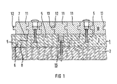
- the structural concrete 2 determining the wall 1 carries a sub-layer 3 of refractory concrete, which is in shape of prefabricated blocks 5 is placed. Blocks 5 are jointed together, because they grip along the joints 6 height-offset projections 7 and 8 one above the other.
- the ceramic stones 11 are also jointed together; because they each engage with a tongue 12 in a groove 13 of the adjacent stone 11.
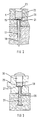
- the anchoring 15 of the blocks 5 on the structural concrete 2 comprises as FIG 2 shows, a threaded sleeve 17, which is in a the reinforced concrete 18 screwed in steel reinforcement 18 is.
- a threaded sleeve 17 which is in a the reinforced concrete 18 screwed in steel reinforcement 18 is.
- Upwards is the recess 22 with a zirconium dioxide screw plug 23 locked.
- the ceramic stones 11 of the partial layer 10 are only to be attached to partial layer 3 in a few places.
- steel anchors 25 with a threaded hole 26 inserted, screwed into the screws 27 can.
- the anchors can also be made of ceramic be.
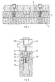
- FIGS. 4 and 5 they are otherwise assembled in the same way from blocks 5 and grouted stones 11 Sub-layers 3 and 10 with ceramic anchors 32 attached to construction concrete 2.
- the ceramic anchor 32 included a threaded sleeve 33 into which a steel screw-in piece 34 is screwed in with a threaded pin 35.
- the screw-in piece 34 has a rectangular profile in cross section and carries a ceramic sleeve 36 to reduce thermal stress.
- a threaded bore 37 leading to the top individual stones 11 are then fastened again with screws 27, which engage in a recess 29 as in FIG. 3 and are covered with a screw plug 30.
- the common attachment 40 of individual stones 11 of the partial layer 10 and of blocks 5 of sub-layer 3 are shown enlarged in FIG. It comprises a metallic anchor screw 41 with a Base plate 42, which consists of a block 5 and the above lying stone 11 extends.
- the anchor screw 41 also extends through the stone 11 into a recess 46. There it carries a nut 47 which presses the bottom of the recess 46. After putting on the Nut 47 can plug recess 46 with a zirconia 48 are closed with a threaded bushing 49 on the end of the anchor screw protruding beyond the nut 47 41 is screwed on.
- FIG 10 shows that the stones 11 despite the grouting fastened with a steel rail 50 with a T-shaped cross section can be on which they also with a cross section T-shaped groove 51 can be pushed on.
- the steel rail 50 is attached to an anchor plate 52 which is in the top individual blocks 5 embedded and fastened with anchor rods 53 is. It runs in the direction perpendicular to the plane of the drawing.
- the anchor plate 52 is like that shown in FIG. 9 Attachment point 40, arranged only on a few stones 11, so that nine and more stones are attached via an anchor plate 52 are.
- the stones 11 have one in cross-section T-shaped profile, the height of projection 55 and undercut 56 is the same so the stones 11 can be stacked into one another by rotating them alternately can.
- Every second row of stones 11 contains in their the base layer 3 facing an anchor 57 with a widened T-shaped head piece protruding from the stone 58. With this these stones are in a rail 59 inserted with a C-shaped profile in the underlying block 5, so that they are fixed and at the same time with its projection 55 an adjacent row of stones 11 without anchors 57 hold down.
- the projections 55 and undercuts 56 can, as has been explained with reference to FIG extend in two mutually perpendicular directions.
- FIG 14 shows an enlarged illustration in one Longitudinal section an anchoring of adjacent stones 11, wherein a ceramic anchor 32 in the sub-layer 3 made of refractory Concrete is embedded. This can also be screwed in or screwed in be.
- the ceramic anchor 32 engages at the point of contact of four adjacent stones 11 as a spring in a respective corresponding groove of the stones 11.
- the stones 11 are constructed as shown in FIG 8, wherein only a corresponding modification at the point which engages the armature 32, has taken place. Each stone 11 points for this purpose at a corner point a recess in which a Quarter of the anchor 32 is added. Enclose four stones 11 thus an anchor 32 and are thereby fixed.
- the anchor 32 has a double-T profile and is in the partial layer 3 by a divided and with the sub-layer 3 screwed steel disc attached.
- the anchor 32 can also be embedded directly into sub-layer 3. It is also possible to analog the anchor 32 as a rail of the rail 59 shown in FIG. 11 and FIG. 13.
- 15 and 16 show in a longitudinal section and in a Top view of a connection of blocks 5 of the sub-layer 3 made of fireproof concrete.
- a metallic running along the end face 16 Plate 24 is firmly connected to block 5 via four steel anchors 25.
- a screw 19 is guided through the plate 24 is.
- Two adjacent blocks 5 each meet with their plate 24 together so that the screw 19 through both plates 24 is passed and tightened with a nut 27 is so that the two plates 24 and thus the two blocks 5 are firmly connected.
- the invention is characterized by a multilayer protective layer which, in particular, on the bottom part of the collecting chamber is arranged.
- a first layer of refractory Concrete is in the form of prefabricated blocks and spreads over the construction concrete of the collecting chamber out.
- the blocks are attached to projections the construction concrete in a few places, so that only a few blocks immediately, for example by appropriate ones Anchor with which structural concrete is firmly connected.
- By interlocking also prefabricated ceramic stones a sub-layer is formed on the sub-layer made of fireproof concrete and also only on individual ceramic stones is firmly connected to this.
Landscapes
- Physics & Mathematics (AREA)
- Engineering & Computer Science (AREA)
- Plasma & Fusion (AREA)
- General Engineering & Computer Science (AREA)
- High Energy & Nuclear Physics (AREA)
- Building Environments (AREA)
- Forms Removed On Construction Sites Or Auxiliary Members Thereof (AREA)
- Structure Of Emergency Protection For Nuclear Reactors (AREA)
Description
- FIG 1
- einen Ausschnitt aus einer erfindungsgemäß gestalteten Wand, dem Boden, eines Auffangraumes für Kernschmelze,
- FIG 2
- eine Einzelheit der Verankerung der'Blöcke der Teilschicht aus feuerfestem Beton in größerem Maßstab,
- FIG 3
- eine Einzelheit der Befestigung der Keramiksteine in größerem Maßstab,
- FIG 4
- eine andere Ausführungsform der Wandgestaltung,
- FIG 5
- eine Einzelheit der Befestigung der Keramiksteine nach FIG 4 in größerem Maßstab,
- FIG 6
- eine weitere Ausführungsform der Wandgestaltung,
- FIG 7
- eine Einzelheit der Befestigung der Keramiksteine nach FIG 6 in größerem Maßstab,
- FIG 8
- einen Keramikstein in perspektivischer Darstellung,
- FIG 9
- eine aus Keramiksteinen nach FIG 8 zusammengesetzte Schicht mit der Lage einer Befestigungsstelle,
- FIG 10
- eine Befestigung eines Keramiksteines mit einer Ankerplatte,
- FIG 11
- eine Befestigung eines Keramiksteines mit einer Schiene,
- FIG 12
- eine Anordnung von Zirkon-Steinen mit alternierendem T-Profil,
- FIG 13
- eine Anordnung der Zirkon-Oxid-Steine mit T-Profil in einer Draufsicht,
- FIG 14
- eine Einzelheit der Befestigung der Keramiksteine nach dem Nut-Feder-Prinzip,
- FIG 15
- eine Einzelheit der Befestigung zweier Blöcke der Teilschicht aus feuerfestem Beton in einem Längsschnitt und
- FIG 16
- die Befestigung nach FIG 15 in einer Draufsicht.
Claims (7)
- Kernreaktor mit einer Auffangkammer für Kernschmelze, die zumindest eine Wand, insbesondere einen Boden, mit einer mehrlagigen Schutzschicht umfaßt, wobei eine Teilschicht (3) mit feuerfestem Beton und eine weitere Teilschicht (10) mit Keramiksteinen aufgebaut ist, wobei die Schutzschichten am Konstruktionsbeton (2) der Auffangkammer verankert sind, dadurch gekennzeichnet, daß die Teilschicht (3) aus feuerfestem Beton in Form von vorgefertigten Blöcken(5) ausgebildet ist, die miteinander verfugt und am Konstruktionsbeton (2) befestigt sind, und daß die Teilschicht (10) aus Keramiksteinen (11) an den Blöcken (5) der Teilschicht (3) aus feuerfestem Beton abgespannt ist.
- Kernreaktor nach Anspruch 1, dadurch gekennzeichnet, daß die Keramiksteine (11) miteinander verfugt und nur an einzelnen Stellen abgespannt sind.
- Kernreaktor nach Anspruch 1, dadurch gekennzeichnet, daß die Blöcke (5) aus feuerfestem Beton mit Spannelementen (15) gehalten sind, die in den Konstruktionsbeton (2) einbetoniert sind und durch Aussparungen der Blöcke (5) greifen.
- Kernreaktor nach Anspruch 1, dadurch gekennzeichnet, daß die Keramiksteine (11) mit Keramikankern (32) abgespannt sind.
- Kernreaktor nach Anspruch 4, dadurch gekennzeichnet, daß die Keramikanker (32) Gewindehülsen (33) enthalten.
- Kernreaktor nach Anspruch 1, dadurch gekennzeichnet, daß die Keramiksteine (11) mit T-Ankern (57) befestigt sind, die in C-Schienen (59) sitzen.
- Kernreaktor nach Anspruch 1, dadurch gekennzeichnet, daß Fugen zwischen den Keramiksteinen (11) mit Zirkonfilz ausgefüllt sind.
Applications Claiming Priority (3)
| Application Number | Priority Date | Filing Date | Title |
|---|---|---|---|
| DE19523548A DE19523548C1 (de) | 1995-06-28 | 1995-06-28 | Kernreaktor mit einer Auffangkammer für Kernschmelze |
| DE19523548 | 1995-06-28 | ||
| PCT/DE1996/001059 WO1997001850A1 (de) | 1995-06-28 | 1996-06-14 | Kernreaktor mit einer auffangkammer für kernschmelze |
Publications (2)
| Publication Number | Publication Date |
|---|---|
| EP0835512A1 EP0835512A1 (de) | 1998-04-15 |
| EP0835512B1 true EP0835512B1 (de) | 1999-04-28 |
Family
ID=7765498
Family Applications (1)
| Application Number | Title | Priority Date | Filing Date |
|---|---|---|---|
| EP96921866A Expired - Lifetime EP0835512B1 (de) | 1995-06-28 | 1996-06-14 | Kernreaktor mit einer auffangkammer für kernschmelze |
Country Status (6)
| Country | Link |
|---|---|
| EP (1) | EP0835512B1 (de) |
| JP (1) | JPH11508679A (de) |
| KR (1) | KR19990028338A (de) |
| CN (1) | CN1185228A (de) |
| DE (2) | DE19523548C1 (de) |
| WO (1) | WO1997001850A1 (de) |
Families Citing this family (12)
| Publication number | Priority date | Publication date | Assignee | Title |
|---|---|---|---|---|
| KR20010000321A (ko) * | 2000-09-15 | 2001-01-05 | 이한웅 | 폐수열 냉각장치 |
| JP4580685B2 (ja) * | 2004-05-24 | 2010-11-17 | 株式会社東芝 | 原子炉格納容器 |
| DE102005032253B4 (de) * | 2005-07-11 | 2008-09-18 | Refractory Intellectual Property Gmbh & Co. Kg | Wannenartige Kernschmelze-Rückhalteeinrichtung |
| JP5377064B2 (ja) * | 2009-04-30 | 2013-12-25 | 株式会社東芝 | 炉心溶融物保持装置および原子力プラント |
| DE102009057680B4 (de) * | 2009-12-09 | 2012-02-23 | Steuler-Industriewerke Gmbh | Befestigungselement für ein chemisch, mechanisch und/oder thermisch belastetes Auskleidungselement sowie Auskleidungseinrichtung |
| JP5710240B2 (ja) * | 2010-12-27 | 2015-04-30 | 株式会社東芝 | 炉心溶融物の保持装置 |
| JP6415874B2 (ja) * | 2014-06-30 | 2018-10-31 | 株式会社東芝 | 原子炉格納容器底部保護装置および原子炉格納設備 |
| KR101606872B1 (ko) * | 2014-07-04 | 2016-03-28 | 주식회사 아리텍 | 노심 용융물 냉각용 다공성 냉각블록 및 이를 구비하는 노심 용융물 냉각장치 및 이들을 이용한 노심 용융물 냉각방법 |
| JP2016197034A (ja) * | 2015-04-02 | 2016-11-24 | 株式会社東芝 | 炉心溶融物保持装置および原子炉施設 |
| JP6525746B2 (ja) * | 2015-06-04 | 2019-06-05 | 日立Geニュークリア・エナジー株式会社 | 耐熱材および原子炉設備 |
| JP2017058313A (ja) * | 2015-09-18 | 2017-03-23 | 株式会社東芝 | コアキャッチャー及びこれを備えた原子炉格納容器 |
| JP6727690B2 (ja) * | 2016-11-17 | 2020-07-22 | 日立Geニュークリア・エナジー株式会社 | 炉心溶融物保持装置 |
Family Cites Families (8)
| Publication number | Priority date | Publication date | Assignee | Title |
|---|---|---|---|---|
| FR2108896B1 (de) * | 1970-10-16 | 1973-11-23 | Commissariat Energie Atomique | |
| US3702802A (en) * | 1971-06-16 | 1972-11-14 | Atomic Energy Commission | Nuclear reactor incorporating means for preventing molten fuel from breaching the containment vessel thereof in the event of a core meltdown |
| US3979866A (en) * | 1973-10-23 | 1976-09-14 | Nuclear Power Co. (Whetstone) Limited | Nuclear reactors |
| DE2557884A1 (de) * | 1975-12-22 | 1977-06-30 | Interatom | Schutzschicht fuer bodenkuehler |
| DE2741795A1 (de) * | 1977-09-16 | 1979-03-29 | Interatom | Kernreaktorauffangwanne mit waermeisolierung |
| GB2236210B (en) * | 1989-08-30 | 1993-06-30 | Rolls Royce & Ass | Core catchers for nuclear reactors |
| US5307390A (en) * | 1992-11-25 | 1994-04-26 | General Electric Company | Corium protection assembly |
| DE4337367A1 (de) * | 1993-06-08 | 1994-12-15 | Siemens Ag | Verschlußeinrichtung zum Ingangsetzen der Kühlung für eine Kernschmelze |
-
1995
- 1995-06-28 DE DE19523548A patent/DE19523548C1/de not_active Expired - Fee Related
-
1996
- 1996-06-14 JP JP9504079A patent/JPH11508679A/ja active Pending
- 1996-06-14 CN CN96194127A patent/CN1185228A/zh active Pending
- 1996-06-14 DE DE59601781T patent/DE59601781D1/de not_active Expired - Lifetime
- 1996-06-14 WO PCT/DE1996/001059 patent/WO1997001850A1/de not_active Ceased
- 1996-06-14 EP EP96921866A patent/EP0835512B1/de not_active Expired - Lifetime
- 1996-06-14 KR KR1019970709653A patent/KR19990028338A/ko not_active Withdrawn
Also Published As
| Publication number | Publication date |
|---|---|
| JPH11508679A (ja) | 1999-07-27 |
| EP0835512A1 (de) | 1998-04-15 |
| WO1997001850A1 (de) | 1997-01-16 |
| DE59601781D1 (de) | 1999-06-02 |
| KR19990028338A (ko) | 1999-04-15 |
| DE19523548C1 (de) | 1996-11-21 |
| CN1185228A (zh) | 1998-06-17 |
Similar Documents
| Publication | Publication Date | Title |
|---|---|---|
| EP0835512B1 (de) | Kernreaktor mit einer auffangkammer für kernschmelze | |
| EP0784127A1 (de) | Verankerungselement für Stahlbetonbauten | |
| LU86218A1 (de) | Formstein | |
| DE3910286A1 (de) | Vorrichtung zum verankern von bauelementen an einem tragenden verankerungsgrund | |
| EP0164330B1 (de) | Stahlbetondecke | |
| CH675738A5 (en) | Noise barrier - consists of basic panel with thickened outer edge making recess for an absorbent layer | |
| DE69524377T2 (de) | Verbindungs- oder Verankerungsvorrichtung von Bewehrungsstäben hoher Haftung im Stahlbeton und Verfahren zu ihrer Realisierung | |
| DE2939472A1 (de) | Spannbetonkoerper mit vorgespannten spanngliedern | |
| DE19630552C2 (de) | Bauelement zur Wärmedämmung | |
| EP0964966B1 (de) | Anschlusselement mit einem dämmkörper | |
| DE3009167A1 (de) | Grabmal-fundamentanordnung | |
| DE2313272C2 (de) | Montagevorrichtung zum Befestigen von Fertigbauteilen | |
| DE9406442U1 (de) | Bauelement | |
| EP0967339B1 (de) | Balkon an einer Gebäudewand | |
| DE3153198C2 (de) | Einbaulehre für mindestens zwei getrennte Ankerelemente | |
| DE1759843A1 (de) | Dach- und Wandkonstruktion u.dgl. | |
| DE4203223C2 (de) | ||
| DE2358146B2 (de) | Gebaeudedecke | |
| DE2163480C3 (de) | Zweischalige Decke | |
| EP4299861A1 (de) | Anordnung und verfahren zum nachträglichen verstärken eines bauteils mit mindestens einem diskontinuitätsbereich | |
| DE29621498U1 (de) | Bauteil aus einem Fachwerkträgersystem | |
| DE8511173U1 (de) | Wandverkleidung | |
| DE29601696U1 (de) | Verbindungselement | |
| DE29622706U1 (de) | Befestigungselement zur Sicherung einer Kopfschraube in einer Ankerschiene | |
| DE9107996U1 (de) | Dübeleinbauteil bei Spannbetonbindern für Verbundkonstruktionen mit Dachplatten aus Stahlbeton |
Legal Events
| Date | Code | Title | Description |
|---|---|---|---|
| PUAI | Public reference made under article 153(3) epc to a published international application that has entered the european phase |
Free format text: ORIGINAL CODE: 0009012 |
|
| 17P | Request for examination filed |
Effective date: 19971218 |
|
| AK | Designated contracting states |
Kind code of ref document: A1 Designated state(s): CH DE ES FR GB LI |
|
| GRAG | Despatch of communication of intention to grant |
Free format text: ORIGINAL CODE: EPIDOS AGRA |
|
| 17Q | First examination report despatched |
Effective date: 19980623 |
|
| GRAG | Despatch of communication of intention to grant |
Free format text: ORIGINAL CODE: EPIDOS AGRA |
|
| GRAH | Despatch of communication of intention to grant a patent |
Free format text: ORIGINAL CODE: EPIDOS IGRA |
|
| GRAH | Despatch of communication of intention to grant a patent |
Free format text: ORIGINAL CODE: EPIDOS IGRA |
|
| GRAA | (expected) grant |
Free format text: ORIGINAL CODE: 0009210 |
|
| AK | Designated contracting states |
Kind code of ref document: B1 Designated state(s): CH DE ES FR GB LI |
|
| PG25 | Lapsed in a contracting state [announced via postgrant information from national office to epo] |
Ref country code: GB Free format text: LAPSE BECAUSE OF FAILURE TO SUBMIT A TRANSLATION OF THE DESCRIPTION OR TO PAY THE FEE WITHIN THE PRESCRIBED TIME-LIMIT Effective date: 19990428 Ref country code: ES Free format text: THE PATENT HAS BEEN ANNULLED BY A DECISION OF A NATIONAL AUTHORITY Effective date: 19990428 |
|
| REG | Reference to a national code |
Ref country code: CH Ref legal event code: EP |
|
| REF | Corresponds to: |
Ref document number: 59601781 Country of ref document: DE Date of ref document: 19990602 |
|
| ET | Fr: translation filed | ||
| GBV | Gb: ep patent (uk) treated as always having been void in accordance with gb section 77(7)/1977 [no translation filed] |
Effective date: 19990428 |
|
| PLBE | No opposition filed within time limit |
Free format text: ORIGINAL CODE: 0009261 |
|
| STAA | Information on the status of an ep patent application or granted ep patent |
Free format text: STATUS: NO OPPOSITION FILED WITHIN TIME LIMIT |
|
| 26N | No opposition filed | ||
| PG25 | Lapsed in a contracting state [announced via postgrant information from national office to epo] |
Ref country code: LI Free format text: LAPSE BECAUSE OF NON-PAYMENT OF DUE FEES Effective date: 20000630 Ref country code: CH Free format text: LAPSE BECAUSE OF NON-PAYMENT OF DUE FEES Effective date: 20000630 |
|
| REG | Reference to a national code |
Ref country code: CH Ref legal event code: PL |
|
| REG | Reference to a national code |
Ref country code: FR Ref legal event code: TP Ref country code: FR Ref legal event code: CD |
|
| REG | Reference to a national code |
Ref country code: FR Ref legal event code: CD Ref country code: FR Ref legal event code: CA |
|
| REG | Reference to a national code |
Ref country code: DE Ref legal event code: R082 Ref document number: 59601781 Country of ref document: DE Representative=s name: TERGAU & WALKENHORST PATENTANWAELTE - RECHTSAN, DE |
|
| REG | Reference to a national code |
Ref country code: DE Ref legal event code: R082 Ref document number: 59601781 Country of ref document: DE Representative=s name: TERGAU & WALKENHORST PATENTANWAELTE PARTGMBB, DE Effective date: 20130618 Ref country code: DE Ref legal event code: R082 Ref document number: 59601781 Country of ref document: DE Representative=s name: TERGAU & WALKENHORST PATENTANWAELTE - RECHTSAN, DE Effective date: 20130618 Ref country code: DE Ref legal event code: R081 Ref document number: 59601781 Country of ref document: DE Owner name: AREVA GMBH, DE Free format text: FORMER OWNER: AREVA NP GMBH, 91052 ERLANGEN, DE Effective date: 20130618 |
|
| PGFP | Annual fee paid to national office [announced via postgrant information from national office to epo] |
Ref country code: DE Payment date: 20140630 Year of fee payment: 19 |
|
| PGFP | Annual fee paid to national office [announced via postgrant information from national office to epo] |
Ref country code: FR Payment date: 20140617 Year of fee payment: 19 |
|
| REG | Reference to a national code |
Ref country code: DE Ref legal event code: R119 Ref document number: 59601781 Country of ref document: DE |
|
| REG | Reference to a national code |
Ref country code: FR Ref legal event code: ST Effective date: 20160229 |
|
| PG25 | Lapsed in a contracting state [announced via postgrant information from national office to epo] |
Ref country code: DE Free format text: LAPSE BECAUSE OF NON-PAYMENT OF DUE FEES Effective date: 20160101 |
|
| PG25 | Lapsed in a contracting state [announced via postgrant information from national office to epo] |
Ref country code: FR Free format text: LAPSE BECAUSE OF NON-PAYMENT OF DUE FEES Effective date: 20150630 |