EP0835670A2 - Beatmungsgeräte - Google Patents
Beatmungsgeräte Download PDFInfo
- Publication number
- EP0835670A2 EP0835670A2 EP97307648A EP97307648A EP0835670A2 EP 0835670 A2 EP0835670 A2 EP 0835670A2 EP 97307648 A EP97307648 A EP 97307648A EP 97307648 A EP97307648 A EP 97307648A EP 0835670 A2 EP0835670 A2 EP 0835670A2
- Authority
- EP
- European Patent Office
- Prior art keywords
- flow
- patient
- ventilator
- pause
- cycle
- Prior art date
- Legal status (The legal status is an assumption and is not a legal conclusion. Google has not performed a legal analysis and makes no representation as to the accuracy of the status listed.)
- Withdrawn
Links
- 230000003434 inspiratory effect Effects 0.000 claims abstract description 22
- 239000007789 gas Substances 0.000 claims description 42
- 210000004072 lung Anatomy 0.000 claims description 18
- 238000000034 method Methods 0.000 claims description 7
- 238000012544 monitoring process Methods 0.000 claims 2
- 230000029058 respiratory gaseous exchange Effects 0.000 abstract description 4
- 206010002091 Anaesthesia Diseases 0.000 description 2
- 230000037005 anaesthesia Effects 0.000 description 2
- 238000010586 diagram Methods 0.000 description 2
- 230000006870 function Effects 0.000 description 2
- 230000010354 integration Effects 0.000 description 2
- 230000004044 response Effects 0.000 description 2
- QVGXLLKOCUKJST-UHFFFAOYSA-N atomic oxygen Chemical compound [O] QVGXLLKOCUKJST-UHFFFAOYSA-N 0.000 description 1
- 230000009286 beneficial effect Effects 0.000 description 1
- 230000002457 bidirectional effect Effects 0.000 description 1
- 238000004364 calculation method Methods 0.000 description 1
- 230000000977 initiatory effect Effects 0.000 description 1
- 239000001301 oxygen Substances 0.000 description 1
- 229910052760 oxygen Inorganic materials 0.000 description 1
- 239000013643 reference control Substances 0.000 description 1
- 238000009423 ventilation Methods 0.000 description 1
Images

Classifications
-
- A—HUMAN NECESSITIES
- A61—MEDICAL OR VETERINARY SCIENCE; HYGIENE
- A61M—DEVICES FOR INTRODUCING MEDIA INTO, OR ONTO, THE BODY; DEVICES FOR TRANSDUCING BODY MEDIA OR FOR TAKING MEDIA FROM THE BODY; DEVICES FOR PRODUCING OR ENDING SLEEP OR STUPOR
- A61M16/00—Devices for influencing the respiratory system of patients by gas treatment, e.g. ventilators; Tracheal tubes
- A61M16/0057—Pumps therefor
- A61M16/0081—Bag or bellow in a bottle
-
- A—HUMAN NECESSITIES
- A61—MEDICAL OR VETERINARY SCIENCE; HYGIENE
- A61M—DEVICES FOR INTRODUCING MEDIA INTO, OR ONTO, THE BODY; DEVICES FOR TRANSDUCING BODY MEDIA OR FOR TAKING MEDIA FROM THE BODY; DEVICES FOR PRODUCING OR ENDING SLEEP OR STUPOR
- A61M16/00—Devices for influencing the respiratory system of patients by gas treatment, e.g. ventilators; Tracheal tubes
- A61M16/021—Devices for influencing the respiratory system of patients by gas treatment, e.g. ventilators; Tracheal tubes operated by electrical means
- A61M16/022—Control means therefor
- A61M16/024—Control means therefor including calculation means, e.g. using a processor
-
- A—HUMAN NECESSITIES
- A61—MEDICAL OR VETERINARY SCIENCE; HYGIENE
- A61M—DEVICES FOR INTRODUCING MEDIA INTO, OR ONTO, THE BODY; DEVICES FOR TRANSDUCING BODY MEDIA OR FOR TAKING MEDIA FROM THE BODY; DEVICES FOR PRODUCING OR ENDING SLEEP OR STUPOR
- A61M16/00—Devices for influencing the respiratory system of patients by gas treatment, e.g. ventilators; Tracheal tubes
- A61M16/0003—Accessories therefor, e.g. sensors, vibrators, negative pressure
- A61M2016/0015—Accessories therefor, e.g. sensors, vibrators, negative pressure inhalation detectors
- A61M2016/0018—Accessories therefor, e.g. sensors, vibrators, negative pressure inhalation detectors electrical
- A61M2016/0021—Accessories therefor, e.g. sensors, vibrators, negative pressure inhalation detectors electrical with a proportional output signal, e.g. from a thermistor
-
- A—HUMAN NECESSITIES
- A61—MEDICAL OR VETERINARY SCIENCE; HYGIENE
- A61M—DEVICES FOR INTRODUCING MEDIA INTO, OR ONTO, THE BODY; DEVICES FOR TRANSDUCING BODY MEDIA OR FOR TAKING MEDIA FROM THE BODY; DEVICES FOR PRODUCING OR ENDING SLEEP OR STUPOR
- A61M16/00—Devices for influencing the respiratory system of patients by gas treatment, e.g. ventilators; Tracheal tubes
- A61M16/0003—Accessories therefor, e.g. sensors, vibrators, negative pressure
- A61M2016/003—Accessories therefor, e.g. sensors, vibrators, negative pressure with a flowmeter
- A61M2016/0033—Accessories therefor, e.g. sensors, vibrators, negative pressure with a flowmeter electrical
- A61M2016/0039—Accessories therefor, e.g. sensors, vibrators, negative pressure with a flowmeter electrical in the inspiratory circuit
-
- A—HUMAN NECESSITIES
- A61—MEDICAL OR VETERINARY SCIENCE; HYGIENE
- A61M—DEVICES FOR INTRODUCING MEDIA INTO, OR ONTO, THE BODY; DEVICES FOR TRANSDUCING BODY MEDIA OR FOR TAKING MEDIA FROM THE BODY; DEVICES FOR PRODUCING OR ENDING SLEEP OR STUPOR
- A61M16/00—Devices for influencing the respiratory system of patients by gas treatment, e.g. ventilators; Tracheal tubes
- A61M16/0003—Accessories therefor, e.g. sensors, vibrators, negative pressure
- A61M2016/003—Accessories therefor, e.g. sensors, vibrators, negative pressure with a flowmeter
- A61M2016/0033—Accessories therefor, e.g. sensors, vibrators, negative pressure with a flowmeter electrical
- A61M2016/0042—Accessories therefor, e.g. sensors, vibrators, negative pressure with a flowmeter electrical in the expiratory circuit
-
- A—HUMAN NECESSITIES
- A61—MEDICAL OR VETERINARY SCIENCE; HYGIENE
- A61M—DEVICES FOR INTRODUCING MEDIA INTO, OR ONTO, THE BODY; DEVICES FOR TRANSDUCING BODY MEDIA OR FOR TAKING MEDIA FROM THE BODY; DEVICES FOR PRODUCING OR ENDING SLEEP OR STUPOR
- A61M2205/00—General characteristics of the apparatus
- A61M2205/33—Controlling, regulating or measuring
- A61M2205/3331—Pressure; Flow
- A61M2205/3344—Measuring or controlling pressure at the body treatment site
Definitions
- This invention relates to medical ventilators for providing breaths to a patient and, more particularly, to a ventilator having a system to provide a zero flow condition during a pause phase following a mechanical inspiration.
- medical ventilator systems are used in the administration of anesthesia to a patient undergoing an operation to maintain the patient under anesthesia until the cessation of the operation.
- the ventilators employ an inspiratory pause period following a mechanical inspiration, which has a beneficial physiological advantage of improving patient oxygen under certain conditions.
- the pause phase allows the clinician to obtain certain physiological information concerning that patient, and specifically, it is useful to determine measures of the patients lung compliance and airway resistance as valuable data in evaluating the patient.
- the lung compliance is an indication of the springiness or elasticity of the lungs and the airway resistance is the pneumatic resistance of the patient's airways from the mouth where the ventilator is connected to the internal volume of the lungs.
- a determination of the lung compliance and resistance through use of a pause is typically accomplished through the use of the following equation derived from a simple linear model: Where:
- the values for the equation are taken during the normal inhalation of the lungs and the values are generally selected at two points, one at the end of the inspiration where the patient pressure is at a peak, P MAX and a second condition after the ventilator provides the pause so that the flow to and from the patient is zero. At that point, the patient airway pressure sample is termed P PLATEAU .
- P PLATEAU the patient airway pressure sample
- the equation is easily solved for the patient compliance (C PAT ). With that value thus determined, it can be used in the equation taken at P MAX at the initiation of the pause period with the then known peak flow information and the equation can be solved for the patient airway resistance. In this fashion, the clinician can readily determine measures of the patient airway resistance and the lung compliance.
- the system of the present invention therefore corrects the aforedescribed problem by providing a system for insuring that zero flow conditions exist at the end of the pause period.
- the airway pressure at that point, the plateau pressure is the same as the pressure within the patient's lungs.
- a method of controlling the flow of gas delivered to a patient comprising the steps of:-
- a ventilator system as described in U.S. Patent 5,315,989 may be utilized and that system can determine the flow at the patient airway to provide an input to a controller to use the ventilator drive pressure to control the flow to a zero flow condition at the end of the pause period.
- a preferred algorithm continually senses that flow and readjusts the control pressure in the patient exhalation circuit until the zero flow conditions are attained.
- the ventilator drive pressures By use of the ventilator drive pressures, the operator is assured that a zero flow condition is met at the end of the pause period.
- accurate determinations can be made of the airway resistance and lung compliance and a more theoretical pause profile is achieved.
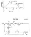
- FIG. 1 there is shown a pressure diagram for a typical airway pressure profile during a volume inspiratory cycle including a pause period.
- the pressure rises from the zero point at point A to the P MAX at point B which is the measured airway pressure at the end of inspiration.
- the value of P MAX is thus measured at the end of the inspiratory cycle and the airway flow (Q AW ) can be determined from the ventilator settings or supplied by the ventilator.
- the pause period takes place between the P MAX at point B and the end of the pause at point C where the airway pressure is reduced to P PLATEAU which, again, is a measured value.
- flow in the patient airway Q AW is considered to be zero in order to solve the equations of the resistance/compliance lung model.
- FIG. 2 there is shown a schematic view of a ventilator apparatus suitable for carrying out the present invention.
- the mechanical aspects of the ventilator apparatus are similar to those disclosed in U.S. Patent 5,315,989 of Tobia and the disclosure of which is incorporated herein by reference, however, there are some differences in the systems and such differences will become apparent from the following description.
- Ventilator 10 comprises a gas source 12 which typically provides gas at about 50 psi through a primary regulator 14 to source conduit 16 and which thus supplies flow control valve 18 with gas at approximately 25 psi.
- Flow control valve 18 is preferably a proportional solenoid valve and which controls the magnitude of gas flow into conduit 20.
- Conduit 22 communicates with conduit 20 and provides an inspiratory flow branch to ventilator connection 24.
- An expiratory flow branch is provided by conduit 32 which functions to convey gas from ventilator connection 24 to expiratory valve 28.
- Check valve 30 is located in conduit 22 to prevent flow from conduits 22 and 32 into conduit 20 during expiration of gas from ventilator connection 24.
- Expiratory valve 28 controls the pressure and flow through conduit 32.
- Expiratory valve 28 is preferably a diaphragm or balloon type of valve which is capable of controlling the pressure in conduit 32 according to a reference pressure.
- Reference control pressure is provided to expiratory valve 28 via the pressure control conduit 26.
- a flow restrictor 34 is provided on vent conduit 36 to provide a bleed for the pressure control conduit 26.
- gas pressure in expiratory conduit 32 exceeds the reference pressure in conduit 26
- gas is exhausted from expiratory conduit 32 through expiratory valve 28 to the atmosphere.
- the pressure in expiratory conduit 32 is controlled by the reference pressure in pressure control conduit 26 which, in turn, is controlled by the flow control valve 18.
- Ventilator connection 24 is made to a bellows assembly 38 and conduit 22 communicates with the bellows outer chamber 40 to actuate bellows 42.
- the patients breathing circuit 44 is in communication with the interior of the bellows 42 and thus is isolated from the gas in the ventilator 10.
- Patient breathing circuit 44 is a circle system comprising an inhalation limb 46 and an exhalation limb 48 that delivers breathing gas to and receives exhaled gas from, respectively, patient connection 50.
- An inspiratory flow sensor 52 is located in the inhalation limb 46 and an expiratory flow sensor 54 is located in the exhalation limb 48 to monitor the flow in the inhalation and exhalation limbs 46,48, that is the flow to and from the patient connection 50.
- Both the inspiratory flow sensor 52 and the expiratory flow sensor 54 monitor flow and communicate signals representative of that flow to a processor 60 as will be explained.
- Pressure sensor 62 communicates with the interior of conduit 20 and provides a signal indicative of the pressure within circuit 20 to processor 60 via a signal line 64.
- the pressure in conduit 20 will be referred to as the manifold pressure or P MAN and, as can be seen, is indicative of the pressure within pressure control conduit 26.
- Processor 60 includes a microprocessor connected via an electronic bus to read only memory (ROM) and random access memory (RAM) in a known digital computer configuration.
- Waveform generator 66 provides a desired waveform to processor 60.
- Flow control valve 18 is controlled by the processor 60 via a control signal line 68 to track the desired pressure waveform established by the user.
- Conduits 20, 22 and 32 thus define a ventilator circuit which communicates with the ventilator connection 24.
- the ventilator 10 operates in the flow delivery mode whereby flow is delivered from gas source 12 through the flow control valve 18 to conduits 20 and 22 and finally to the ventilator connection 24.
- check valve 30 prevents flow from conduit 22 to conduit 20 and gas flows via conduit 32 to expiratory valve 28 where it is exhausted to the atmosphere.
- the ventilator thus operates in a flow exhaust mode.
- the flow control valve 18 In order to maintain a positive pressure at ventilator connection 24 during the pause phase of the breath cycle, the flow control valve 18 is adjusted so as to maintain a small amount of flow exhausting across flow restrictor 34. Thus, pressure is generated in pressure control conduit 26 which serves to bias shut expiratory valve 28, holding pressure in expiratory conduit 32, ventilator connection 24 and concomitantly at the patient connection 50.
- pressure control conduit 26 which serves to bias shut expiratory valve 28, holding pressure in expiratory conduit 32, ventilator connection 24 and concomitantly at the patient connection 50.
- the prior model assumption that the flow is zero at the end of the pause period is assured by adjusting the circuit pressure during the pause period to drive the end of the pause flow to converge on zero and thus, assure that the P AW measured at the end of the pause period is, in fact, equal to the patient lung pressure.
- FIG. 3 there is shown a flow chart of the preferred method of assuring a zero flow at the end of the pause period.
- a proximal flow sensing block 80 that receives information from a flow sensor that monitors the flow to and from the patient during the pause period. That flow can be positive indicating that there was a flow to the patient or may be negative indicating that a flow was received from the patient.
- the flow sensor may be as shown in FIG. 2 where two sensors are utilized, or a single bidirectional flow sensor may be used in the patient airway.
- a standard PI controller 92 adjusts a Pause Pressure Delta on a breath to breath basis. That Pause Pressure Delta is added to the previous breath's PMAX that is continuously monitored in the ventilator in order to provide a target pressure (Pause Pressure) to be held by the expiratory valve (FIG. 2) during the pause period.
- a target pressure Pause Pressure
- the PI controller 92 is able to cause a pause pressure to be applied to the expiratory valve which produces a zero flow end pause condition at the patient airway.
- the pause pressure may change through an adjustment of the Pause Pressure Delta. This adjustment may increase the pause pressure to the expiration valve, resulting in higher (more positive) end pause flows to the patient, or may decrease the pause pressure, thereby resulting in lower (more negative) flow at the end of the pause period.
- a zero end pause flow condition it is possible for a zero end pause flow condition to exist even though a significant amount of flow has been released from the lungs earlier in the pause period. For example, with a very negative pause delta and a long pause period, a period of partial exhalation may occur earlier in the pause period but be stabilized to zero flow at the end of the pause period.
- the delivered volume during the pause period is integrated at flow integration block 84.
- the decision block 82 determines if the pause flow volume is less than zero volume and if it is determined to be so, the PI controller is bypassed and the Pause Pressure Delta is incremented by a preset or calculated amount, determined in block 86, which is independent of the flow sensed in block 80.
Landscapes
- Health & Medical Sciences (AREA)
- Emergency Medicine (AREA)
- Pulmonology (AREA)
- Engineering & Computer Science (AREA)
- Anesthesiology (AREA)
- Biomedical Technology (AREA)
- Heart & Thoracic Surgery (AREA)
- Hematology (AREA)
- Life Sciences & Earth Sciences (AREA)
- Animal Behavior & Ethology (AREA)
- General Health & Medical Sciences (AREA)
- Public Health (AREA)
- Veterinary Medicine (AREA)
- Measurement Of The Respiration, Hearing Ability, Form, And Blood Characteristics Of Living Organisms (AREA)
Applications Claiming Priority (2)
| Application Number | Priority Date | Filing Date | Title |
|---|---|---|---|
| US2761396P | 1996-10-10 | 1996-10-10 | |
| US27613P | 1996-10-10 |
Publications (2)
| Publication Number | Publication Date |
|---|---|
| EP0835670A2 true EP0835670A2 (de) | 1998-04-15 |
| EP0835670A3 EP0835670A3 (de) | 1998-09-09 |
Family
ID=21838740
Family Applications (1)
| Application Number | Title | Priority Date | Filing Date |
|---|---|---|---|
| EP97307648A Withdrawn EP0835670A3 (de) | 1996-10-10 | 1997-09-29 | Beatmungsgeräte |
Country Status (2)
| Country | Link |
|---|---|
| US (1) | US6371113B1 (de) |
| EP (1) | EP0835670A3 (de) |
Cited By (1)
| Publication number | Priority date | Publication date | Assignee | Title |
|---|---|---|---|---|
| US6152131A (en) * | 1998-08-26 | 2000-11-28 | Instrumentarium Corp. | Method and apparatus for detecting an empty breathing gas compartment in a patient ventilator |
Families Citing this family (61)
| Publication number | Priority date | Publication date | Assignee | Title |
|---|---|---|---|---|
| US7758503B2 (en) | 1997-01-27 | 2010-07-20 | Lynn Lawrence A | Microprocessor system for the analysis of physiologic and financial datasets |
| US20050062609A9 (en) * | 1992-08-19 | 2005-03-24 | Lynn Lawrence A. | Pulse oximetry relational alarm system for early recognition of instability and catastrophic occurrences |
| US9468378B2 (en) * | 1997-01-27 | 2016-10-18 | Lawrence A. Lynn | Airway instability detection system and method |
| US8932227B2 (en) * | 2000-07-28 | 2015-01-13 | Lawrence A. Lynn | System and method for CO2 and oximetry integration |
| US9042952B2 (en) * | 1997-01-27 | 2015-05-26 | Lawrence A. Lynn | System and method for automatic detection of a plurality of SPO2 time series pattern types |
| US20060155207A1 (en) * | 1997-01-27 | 2006-07-13 | Lynn Lawrence A | System and method for detection of incomplete reciprocation |
| US20070191697A1 (en) * | 2006-02-10 | 2007-08-16 | Lynn Lawrence A | System and method for SPO2 instability detection and quantification |
| US6581601B2 (en) * | 1999-06-18 | 2003-06-24 | Saeed Ziaee | Nasal mask with balloon exhalation valve |
| US6626175B2 (en) * | 2000-10-06 | 2003-09-30 | Respironics, Inc. | Medical ventilator triggering and cycling method and mechanism |
| US9053222B2 (en) * | 2002-05-17 | 2015-06-09 | Lawrence A. Lynn | Patient safety processor |
| FR2858236B1 (fr) | 2003-07-29 | 2006-04-28 | Airox | Dispositif et procede de fourniture de gaz respiratoire en pression ou en volume |
| US8561611B2 (en) * | 2005-06-21 | 2013-10-22 | Ric Investments, Llc | Respiratory device measurement system |
| CN100998902B (zh) * | 2006-01-13 | 2010-12-08 | 深圳迈瑞生物医疗电子股份有限公司 | 流量监测与控制的装置 |
| US7706852B2 (en) * | 2006-01-30 | 2010-04-27 | Nellcor Puritan Bennett Llc | System and method for detection of unstable oxygen saturation |
| US7668579B2 (en) * | 2006-02-10 | 2010-02-23 | Lynn Lawrence A | System and method for the detection of physiologic response to stimulation |
| US7861716B2 (en) * | 2006-03-15 | 2011-01-04 | Carefusion 207, Inc. | Closed loop control system for a high frequency oscillation ventilator |
| US20080029096A1 (en) * | 2006-08-02 | 2008-02-07 | Kollmeyer Phillip J | Pressure targeted ventilator using an oscillating pump |
| US8960193B2 (en) * | 2007-02-16 | 2015-02-24 | General Electric Company | Mobile medical ventilator |
| US8275553B2 (en) | 2008-02-19 | 2012-09-25 | Nellcor Puritan Bennett Llc | System and method for evaluating physiological parameter data |
| US8365730B2 (en) | 2008-03-24 | 2013-02-05 | Covidien Lp | Method and system for classification of photo-plethysmographically detected respiratory effort |
| US20090247837A1 (en) * | 2008-03-27 | 2009-10-01 | Nellcor Puritan Bennett Llc | System And Method For Diagnosing Sleep Apnea |
| US8457706B2 (en) * | 2008-05-16 | 2013-06-04 | Covidien Lp | Estimation of a physiological parameter using a neural network |
| US8398555B2 (en) * | 2008-09-10 | 2013-03-19 | Covidien Lp | System and method for detecting ventilatory instability |
| CA2736540C (en) | 2008-09-25 | 2015-11-24 | Nellcor Puritan Bennett Llc | Inversion-based feed-forward compensation of inspiratory trigger dynamics in medical ventilators |
| US8302602B2 (en) | 2008-09-30 | 2012-11-06 | Nellcor Puritan Bennett Llc | Breathing assistance system with multiple pressure sensors |
| US8434479B2 (en) * | 2009-02-27 | 2013-05-07 | Covidien Lp | Flow rate compensation for transient thermal response of hot-wire anemometers |
| US20100218766A1 (en) * | 2009-02-27 | 2010-09-02 | Nellcor Puritan Bennett Llc | Customizable mandatory/spontaneous closed loop mode selection |
| US20100288283A1 (en) * | 2009-05-15 | 2010-11-18 | Nellcor Puritan Bennett Llc | Dynamic adjustment of tube compensation factor based on internal changes in breathing tube |
| US8439037B2 (en) * | 2009-12-01 | 2013-05-14 | Covidien Lp | Exhalation valve assembly with integrated filter and flow sensor |
| US8469030B2 (en) | 2009-12-01 | 2013-06-25 | Covidien Lp | Exhalation valve assembly with selectable contagious/non-contagious latch |
| US8469031B2 (en) | 2009-12-01 | 2013-06-25 | Covidien Lp | Exhalation valve assembly with integrated filter |
| US8439036B2 (en) | 2009-12-01 | 2013-05-14 | Covidien Lp | Exhalation valve assembly with integral flow sensor |
| DE102010010248A1 (de) * | 2010-03-03 | 2011-09-08 | Forschungszentrum Borstel Leibniz-Zentrum Für Medizin Und Biowissenschaften | Beatmungsverfahren und Beatmungsgerät |
| USD653749S1 (en) | 2010-04-27 | 2012-02-07 | Nellcor Puritan Bennett Llc | Exhalation module filter body |
| USD655405S1 (en) | 2010-04-27 | 2012-03-06 | Nellcor Puritan Bennett Llc | Filter and valve body for an exhalation module |
| USD655809S1 (en) | 2010-04-27 | 2012-03-13 | Nellcor Puritan Bennett Llc | Valve body with integral flow meter for an exhalation module |
| US8776792B2 (en) | 2011-04-29 | 2014-07-15 | Covidien Lp | Methods and systems for volume-targeted minimum pressure-control ventilation |
| US9629971B2 (en) | 2011-04-29 | 2017-04-25 | Covidien Lp | Methods and systems for exhalation control and trajectory optimization |
| US9364624B2 (en) | 2011-12-07 | 2016-06-14 | Covidien Lp | Methods and systems for adaptive base flow |
| US9498589B2 (en) | 2011-12-31 | 2016-11-22 | Covidien Lp | Methods and systems for adaptive base flow and leak compensation |
| US9327089B2 (en) | 2012-03-30 | 2016-05-03 | Covidien Lp | Methods and systems for compensation of tubing related loss effects |
| US9993604B2 (en) | 2012-04-27 | 2018-06-12 | Covidien Lp | Methods and systems for an optimized proportional assist ventilation |
| US9144658B2 (en) | 2012-04-30 | 2015-09-29 | Covidien Lp | Minimizing imposed expiratory resistance of mechanical ventilator by optimizing exhalation valve control |
| US9375542B2 (en) | 2012-11-08 | 2016-06-28 | Covidien Lp | Systems and methods for monitoring, managing, and/or preventing fatigue during ventilation |
| USD731049S1 (en) | 2013-03-05 | 2015-06-02 | Covidien Lp | EVQ housing of an exhalation module |
| USD692556S1 (en) | 2013-03-08 | 2013-10-29 | Covidien Lp | Expiratory filter body of an exhalation module |
| USD744095S1 (en) | 2013-03-08 | 2015-11-24 | Covidien Lp | Exhalation module EVQ internal flow sensor |
| USD736905S1 (en) | 2013-03-08 | 2015-08-18 | Covidien Lp | Exhalation module EVQ housing |
| USD693001S1 (en) | 2013-03-08 | 2013-11-05 | Covidien Lp | Neonate expiratory filter assembly of an exhalation module |
| USD731065S1 (en) | 2013-03-08 | 2015-06-02 | Covidien Lp | EVQ pressure sensor filter of an exhalation module |
| USD731048S1 (en) | 2013-03-08 | 2015-06-02 | Covidien Lp | EVQ diaphragm of an exhalation module |
| USD701601S1 (en) | 2013-03-08 | 2014-03-25 | Covidien Lp | Condensate vial of an exhalation module |
| US9358355B2 (en) | 2013-03-11 | 2016-06-07 | Covidien Lp | Methods and systems for managing a patient move |
| US9950135B2 (en) | 2013-03-15 | 2018-04-24 | Covidien Lp | Maintaining an exhalation valve sensor assembly |
| USD775345S1 (en) | 2015-04-10 | 2016-12-27 | Covidien Lp | Ventilator console |
| JP6980657B2 (ja) | 2015-12-02 | 2021-12-15 | コーニンクレッカ フィリップス エヌ ヴェKoninklijke Philips N.V. | 非侵襲的換気中のco2測定の方法 |
| WO2019099185A1 (en) | 2017-11-14 | 2019-05-23 | Covidien Lp | Methods and systems for drive pressure spontaneous ventilation |
| WO2019152699A1 (en) * | 2018-01-31 | 2019-08-08 | Respirix, Inc. | Devices and methods for monitoring physiologic parameters |
| US11517691B2 (en) | 2018-09-07 | 2022-12-06 | Covidien Lp | Methods and systems for high pressure controlled ventilation |
| US11896767B2 (en) | 2020-03-20 | 2024-02-13 | Covidien Lp | Model-driven system integration in medical ventilators |
| JP2024518030A (ja) * | 2021-04-15 | 2024-04-24 | ベンテック ライフ システムズ, インコーポレイテッド | 患者肺圧を測定するためのシステムおよび方法 |
Citations (1)
| Publication number | Priority date | Publication date | Assignee | Title |
|---|---|---|---|---|
| US5315989A (en) | 1991-12-09 | 1994-05-31 | Boc Health Care, Inc. | Medical ventilator |
Family Cites Families (25)
| Publication number | Priority date | Publication date | Assignee | Title |
|---|---|---|---|---|
| DE1466825B2 (de) * | 1964-09-28 | 1972-10-12 | Fritz Hellige & Co Gmbh, Fabrik Wissenschaftlicher Apparate, 7800 Freiburg | Vorrichtung zur ermittlung der druck-volimenbeziehung des systems thorax-lunge fuer medizinisch-diagnostische zwecke |
| GB1338226A (en) * | 1970-01-21 | 1973-11-21 | British Oxygen Co Ltd | Lung ventilators |
| GB1299140A (en) | 1971-11-02 | 1972-12-06 | Philips Electronic Associated | Electronically controlled gas pressure meter |
| US3946729A (en) | 1974-10-17 | 1976-03-30 | Hewlett-Packard Company | Ventilator patient monitor |
| US4031885A (en) | 1975-10-15 | 1977-06-28 | Puritan-Bennett Corporation | Method and apparatus for determining patient lung pressure, compliance and resistance |
| US4323064A (en) | 1976-10-26 | 1982-04-06 | Puritan-Bennett Corporation | Volume ventilator |
| GB1583273A (en) | 1977-05-06 | 1981-01-21 | Medishield Corp Ltd | Lung ventilators |
| GB1599672A (en) * | 1977-12-09 | 1981-10-07 | Ireland Vitalograph | Apparatus for the determination of respiratory parameters |
| SE425595B (sv) | 1978-11-29 | 1982-10-18 | Siemens Elema Ab | Anordning vid en andningsapparat |
| DE3021326A1 (de) | 1980-06-06 | 1981-12-17 | Drägerwerk AG, 2400 Lübeck | Einrichtung zur messung von mindestens zwei pneumatischen lungenparametern und messverfahren hierzu |
| JPS5948106B2 (ja) | 1980-08-27 | 1984-11-24 | 株式会社東芝 | 呼吸監視装置 |
| US4393869A (en) | 1981-06-22 | 1983-07-19 | Canadian Patents & Development Limited | Electronically controlled respirator |
| US4448192A (en) | 1982-03-05 | 1984-05-15 | Hewlett Packard Company | Medical ventilator device parametrically controlled for patient ventilation |
| FR2573658B1 (fr) | 1984-11-26 | 1989-02-24 | Air Liquide | Dispositif de pression expiratoire positive |
| US4802492A (en) * | 1987-03-11 | 1989-02-07 | National Jewish Center For Immunology And Respiratory Medicine | Method for determining respiratory function |
| US4883050A (en) | 1988-02-29 | 1989-11-28 | Nortgate Research, Inc. | Circuit providing indication of air entrapment in patient's lungs |
| JPH01223966A (ja) | 1988-03-01 | 1989-09-07 | Sumitomo Bakelite Co Ltd | 人工呼吸器 |
| US5048515A (en) * | 1988-11-15 | 1991-09-17 | Sanso David W | Respiratory gas supply apparatus and method |
| GB8920499D0 (en) * | 1989-09-11 | 1989-10-25 | Micro Medical Ltd | Apparatus for measuring airway resistance |
| US5261397A (en) * | 1991-05-10 | 1993-11-16 | The Children's Hospital Of Philadelphia | Methods and apparatus for measuring infant lung function and providing respiratory system therapy |
| DE4122069A1 (de) | 1991-07-04 | 1993-01-07 | Draegerwerk Ag | Verfahren zur erkennung der atemphasen eines patienten bei assistierenden beatmungsverfahren |
| US5438980A (en) * | 1993-01-12 | 1995-08-08 | Puritan-Bennett Corporation | Inhalation/exhalation respiratory phase detection circuit |
| BR9304638A (pt) * | 1993-12-06 | 1995-07-25 | Intermed Equipamento Medico Ho | Sistema de controle de ciclo respiratório |
| DE4432219C1 (de) * | 1994-09-10 | 1996-04-11 | Draegerwerk Ag | Beatmungssystem zur Versorgung eines Patienten mit Atemgas |
| DE69532011T2 (de) | 1994-10-14 | 2004-07-29 | Bird Products Corporation, Palm Springs | Ausatmungsventil |
-
1997
- 1997-08-22 US US08/916,553 patent/US6371113B1/en not_active Expired - Fee Related
- 1997-09-29 EP EP97307648A patent/EP0835670A3/de not_active Withdrawn
Patent Citations (1)
| Publication number | Priority date | Publication date | Assignee | Title |
|---|---|---|---|---|
| US5315989A (en) | 1991-12-09 | 1994-05-31 | Boc Health Care, Inc. | Medical ventilator |
Cited By (1)
| Publication number | Priority date | Publication date | Assignee | Title |
|---|---|---|---|---|
| US6152131A (en) * | 1998-08-26 | 2000-11-28 | Instrumentarium Corp. | Method and apparatus for detecting an empty breathing gas compartment in a patient ventilator |
Also Published As
| Publication number | Publication date |
|---|---|
| US6371113B1 (en) | 2002-04-16 |
| EP0835670A3 (de) | 1998-09-09 |
Similar Documents
| Publication | Publication Date | Title |
|---|---|---|
| EP0835670A2 (de) | Beatmungsgeräte | |
| US6920875B1 (en) | Average volume ventilation | |
| EP0475993B1 (de) | Medizinische beatmungsgeräte | |
| US5797393A (en) | Method for controlling the respirating phase in a ventilating apparatus | |
| US6820618B2 (en) | Method and apparatus for nullifying the imposed work of breathing | |
| US6017315A (en) | Patient monitor and method of using same | |
| US5319540A (en) | System and method for controlling a periodically actuated ventilation flow system | |
| US7040321B2 (en) | Method for controlling a ventilator, and system therefor | |
| US6390091B1 (en) | Method and apparatus for controlling a medical ventilator | |
| US6544192B2 (en) | Patient monitor and method of using same | |
| US6439229B1 (en) | Pressure support ventilation control system and method | |
| US6532956B2 (en) | Parameter variation for proportional assist ventilation or proportional positive airway pressure support devices | |
| CN102369036B (zh) | 呼吸设备的peep调节 | |
| JP4938185B2 (ja) | 患者呼吸回路の有効流れ抵抗を評価するための方法及び装置 | |
| HK1005853B (en) | Improvements in or relating to medical ventilators | |
| US6651657B1 (en) | Respirator for different forms of respiration | |
| US9272111B2 (en) | Leak estimation using function estimation | |
| US7086098B2 (en) | Mechanical breathing aid with adaptive expiration control | |
| JPH10505765A (ja) | 圧力制御式呼吸補助装置 | |
| CN103813823A (zh) | 用于控制呼吸循环中的最终呼出压强的方法 |
Legal Events
| Date | Code | Title | Description |
|---|---|---|---|
| PUAI | Public reference made under article 153(3) epc to a published international application that has entered the european phase |
Free format text: ORIGINAL CODE: 0009012 |
|
| AK | Designated contracting states |
Kind code of ref document: A2 Designated state(s): AT BE CH DE DK ES FI FR GB GR IE IT LI LU MC NL PT SE |
|
| PUAL | Search report despatched |
Free format text: ORIGINAL CODE: 0009013 |
|
| AK | Designated contracting states |
Kind code of ref document: A3 Designated state(s): AT BE CH DE DK ES FI FR GB GR IE IT LI LU MC NL PT SE |
|
| AKX | Designation fees paid | ||
| RBV | Designated contracting states (corrected) | ||
| STAA | Information on the status of an ep patent application or granted ep patent |
Free format text: STATUS: THE APPLICATION IS DEEMED TO BE WITHDRAWN |
|
| 18D | Application deemed to be withdrawn |
Effective date: 19990310 |
|
| REG | Reference to a national code |
Ref country code: DE Ref legal event code: 8566 |