EP0835743B1 - Dispositif et procédé pour fixer une connexion électrique à un article transparent stratifié - Google Patents
Dispositif et procédé pour fixer une connexion électrique à un article transparent stratifié Download PDFInfo
- Publication number
- EP0835743B1 EP0835743B1 EP97115403A EP97115403A EP0835743B1 EP 0835743 B1 EP0835743 B1 EP 0835743B1 EP 97115403 A EP97115403 A EP 97115403A EP 97115403 A EP97115403 A EP 97115403A EP 0835743 B1 EP0835743 B1 EP 0835743B1
- Authority
- EP
- European Patent Office
- Prior art keywords
- mold
- laminate
- sealant
- fixture
- opening
- Prior art date
- Legal status (The legal status is an assumption and is not a legal conclusion. Google has not performed a legal analysis and makes no representation as to the accuracy of the status listed.)
- Expired - Lifetime
Links
- 238000000034 method Methods 0.000 title claims description 15
- 238000007789 sealing Methods 0.000 title claims description 7
- 239000000565 sealant Substances 0.000 claims description 52
- 238000010438 heat treatment Methods 0.000 claims description 7
- 239000005340 laminated glass Substances 0.000 claims description 5
- 239000012812 sealant material Substances 0.000 claims description 4
- 238000002347 injection Methods 0.000 claims description 3
- 239000007924 injection Substances 0.000 claims description 3
- 229920002379 silicone rubber Polymers 0.000 claims description 3
- 239000004945 silicone rubber Substances 0.000 claims description 3
- 239000011521 glass Substances 0.000 description 19
- 239000000853 adhesive Substances 0.000 description 18
- 230000001070 adhesive effect Effects 0.000 description 18
- 239000011248 coating agent Substances 0.000 description 16
- 238000000576 coating method Methods 0.000 description 16
- 239000000463 material Substances 0.000 description 16
- 239000004593 Epoxy Substances 0.000 description 7
- 229910052751 metal Inorganic materials 0.000 description 6
- 239000002184 metal Substances 0.000 description 6
- ATJFFYVFTNAWJD-UHFFFAOYSA-N Tin Chemical compound [Sn] ATJFFYVFTNAWJD-UHFFFAOYSA-N 0.000 description 5
- 239000011229 interlayer Substances 0.000 description 5
- 230000000670 limiting effect Effects 0.000 description 5
- 239000011135 tin Substances 0.000 description 5
- 229910052718 tin Inorganic materials 0.000 description 5
- 229910001369 Brass Inorganic materials 0.000 description 4
- 230000002411 adverse Effects 0.000 description 4
- 239000010951 brass Substances 0.000 description 4
- 239000000919 ceramic Substances 0.000 description 4
- 229910001220 stainless steel Inorganic materials 0.000 description 4
- 239000010935 stainless steel Substances 0.000 description 4
- 239000006229 carbon black Substances 0.000 description 3
- RYGMFSIKBFXOCR-UHFFFAOYSA-N Copper Chemical compound [Cu] RYGMFSIKBFXOCR-UHFFFAOYSA-N 0.000 description 2
- BLRPTPMANUNPDV-UHFFFAOYSA-N Silane Chemical compound [SiH4] BLRPTPMANUNPDV-UHFFFAOYSA-N 0.000 description 2
- BQCADISMDOOEFD-UHFFFAOYSA-N Silver Chemical compound [Ag] BQCADISMDOOEFD-UHFFFAOYSA-N 0.000 description 2
- 230000004888 barrier function Effects 0.000 description 2
- 230000015556 catabolic process Effects 0.000 description 2
- 229910052802 copper Inorganic materials 0.000 description 2
- 239000010949 copper Substances 0.000 description 2
- 230000008878 coupling Effects 0.000 description 2
- 238000010168 coupling process Methods 0.000 description 2
- 238000005859 coupling reaction Methods 0.000 description 2
- 229920001971 elastomer Polymers 0.000 description 2
- 239000003973 paint Substances 0.000 description 2
- 229920000647 polyepoxide Polymers 0.000 description 2
- 229910000077 silane Inorganic materials 0.000 description 2
- 229910052709 silver Inorganic materials 0.000 description 2
- 239000004332 silver Substances 0.000 description 2
- 239000000126 substance Substances 0.000 description 2
- JOYRKODLDBILNP-UHFFFAOYSA-N Ethyl urethane Chemical compound CCOC(N)=O JOYRKODLDBILNP-UHFFFAOYSA-N 0.000 description 1
- NIXOWILDQLNWCW-UHFFFAOYSA-N acrylic acid group Chemical group C(C=C)(=O)O NIXOWILDQLNWCW-UHFFFAOYSA-N 0.000 description 1
- 239000002390 adhesive tape Substances 0.000 description 1
- 229910052782 aluminium Inorganic materials 0.000 description 1
- XAGFODPZIPBFFR-UHFFFAOYSA-N aluminium Chemical compound [Al] XAGFODPZIPBFFR-UHFFFAOYSA-N 0.000 description 1
- 239000010953 base metal Substances 0.000 description 1
- 239000011324 bead Substances 0.000 description 1
- 238000005452 bending Methods 0.000 description 1
- 230000001413 cellular effect Effects 0.000 description 1
- 239000003086 colorant Substances 0.000 description 1
- 238000002788 crimping Methods 0.000 description 1
- 238000006731 degradation reaction Methods 0.000 description 1
- 230000032798 delamination Effects 0.000 description 1
- 230000000694 effects Effects 0.000 description 1
- 125000003700 epoxy group Chemical group 0.000 description 1
- 239000003822 epoxy resin Substances 0.000 description 1
- 239000011888 foil Substances 0.000 description 1
- 230000005484 gravity Effects 0.000 description 1
- 230000001939 inductive effect Effects 0.000 description 1
- 238000009434 installation Methods 0.000 description 1
- 230000002452 interceptive effect Effects 0.000 description 1
- 230000001788 irregular Effects 0.000 description 1
- 238000003475 lamination Methods 0.000 description 1
- 239000010410 layer Substances 0.000 description 1
- 239000000203 mixture Substances 0.000 description 1
- 230000002093 peripheral effect Effects 0.000 description 1
- 239000004033 plastic Substances 0.000 description 1
- 229920003023 plastic Polymers 0.000 description 1
- 229920002037 poly(vinyl butyral) polymer Polymers 0.000 description 1
- 239000004417 polycarbonate Substances 0.000 description 1
- 229920000515 polycarbonate Polymers 0.000 description 1
- 229920000642 polymer Polymers 0.000 description 1
- 230000002829 reductive effect Effects 0.000 description 1
- 239000012858 resilient material Substances 0.000 description 1
- 229920005989 resin Polymers 0.000 description 1
- 239000011347 resin Substances 0.000 description 1
- 238000007493 shaping process Methods 0.000 description 1
- 229920000260 silastic Polymers 0.000 description 1
- 238000005476 soldering Methods 0.000 description 1
- 239000007921 spray Substances 0.000 description 1
- 230000003068 static effect Effects 0.000 description 1
- -1 wires Substances 0.000 description 1
Images


Classifications
-
- B—PERFORMING OPERATIONS; TRANSPORTING
- B32—LAYERED PRODUCTS
- B32B—LAYERED PRODUCTS, i.e. PRODUCTS BUILT-UP OF STRATA OF FLAT OR NON-FLAT, e.g. CELLULAR OR HONEYCOMB, FORM
- B32B17/00—Layered products essentially comprising sheet glass, or glass, slag, or like fibres
- B32B17/06—Layered products essentially comprising sheet glass, or glass, slag, or like fibres comprising glass as the main or only constituent of a layer, next to another layer of a specific material
- B32B17/10—Layered products essentially comprising sheet glass, or glass, slag, or like fibres comprising glass as the main or only constituent of a layer, next to another layer of a specific material of synthetic resin
- B32B17/10005—Layered products essentially comprising sheet glass, or glass, slag, or like fibres comprising glass as the main or only constituent of a layer, next to another layer of a specific material of synthetic resin laminated safety glass or glazing
- B32B17/10165—Functional features of the laminated safety glass or glazing
- B32B17/10174—Coatings of a metallic or dielectric material on a constituent layer of glass or polymer
- B32B17/10183—Coatings of a metallic or dielectric material on a constituent layer of glass or polymer being not continuous, e.g. in edge regions
-
- B—PERFORMING OPERATIONS; TRANSPORTING
- B29—WORKING OF PLASTICS; WORKING OF SUBSTANCES IN A PLASTIC STATE IN GENERAL
- B29C—SHAPING OR JOINING OF PLASTICS; SHAPING OF MATERIAL IN A PLASTIC STATE, NOT OTHERWISE PROVIDED FOR; AFTER-TREATMENT OF THE SHAPED PRODUCTS, e.g. REPAIRING
- B29C33/00—Moulds or cores; Details thereof or accessories therefor
- B29C33/12—Moulds or cores; Details thereof or accessories therefor with incorporated means for positioning inserts, e.g. labels
-
- B—PERFORMING OPERATIONS; TRANSPORTING
- B29—WORKING OF PLASTICS; WORKING OF SUBSTANCES IN A PLASTIC STATE IN GENERAL
- B29C—SHAPING OR JOINING OF PLASTICS; SHAPING OF MATERIAL IN A PLASTIC STATE, NOT OTHERWISE PROVIDED FOR; AFTER-TREATMENT OF THE SHAPED PRODUCTS, e.g. REPAIRING
- B29C70/00—Shaping composites, i.e. plastics material comprising reinforcements, fillers or preformed parts, e.g. inserts
- B29C70/68—Shaping composites, i.e. plastics material comprising reinforcements, fillers or preformed parts, e.g. inserts by incorporating or moulding on preformed parts, e.g. inserts or layers, e.g. foam blocks
- B29C70/74—Moulding material on a relatively small portion of the preformed part, e.g. outsert moulding
- B29C70/76—Moulding on edges or extremities of the preformed part
- B29C70/763—Moulding on edges or extremities of the preformed part the edges being disposed in a substantial flat plane
-
- B—PERFORMING OPERATIONS; TRANSPORTING
- B32—LAYERED PRODUCTS
- B32B—LAYERED PRODUCTS, i.e. PRODUCTS BUILT-UP OF STRATA OF FLAT OR NON-FLAT, e.g. CELLULAR OR HONEYCOMB, FORM
- B32B17/00—Layered products essentially comprising sheet glass, or glass, slag, or like fibres
- B32B17/06—Layered products essentially comprising sheet glass, or glass, slag, or like fibres comprising glass as the main or only constituent of a layer, next to another layer of a specific material
- B32B17/10—Layered products essentially comprising sheet glass, or glass, slag, or like fibres comprising glass as the main or only constituent of a layer, next to another layer of a specific material of synthetic resin
- B32B17/10005—Layered products essentially comprising sheet glass, or glass, slag, or like fibres comprising glass as the main or only constituent of a layer, next to another layer of a specific material of synthetic resin laminated safety glass or glazing
- B32B17/10009—Layered products essentially comprising sheet glass, or glass, slag, or like fibres comprising glass as the main or only constituent of a layer, next to another layer of a specific material of synthetic resin laminated safety glass or glazing characterized by the number, the constitution or treatment of glass sheets
- B32B17/10036—Layered products essentially comprising sheet glass, or glass, slag, or like fibres comprising glass as the main or only constituent of a layer, next to another layer of a specific material of synthetic resin laminated safety glass or glazing characterized by the number, the constitution or treatment of glass sheets comprising two outer glass sheets
-
- B—PERFORMING OPERATIONS; TRANSPORTING
- B32—LAYERED PRODUCTS
- B32B—LAYERED PRODUCTS, i.e. PRODUCTS BUILT-UP OF STRATA OF FLAT OR NON-FLAT, e.g. CELLULAR OR HONEYCOMB, FORM
- B32B17/00—Layered products essentially comprising sheet glass, or glass, slag, or like fibres
- B32B17/06—Layered products essentially comprising sheet glass, or glass, slag, or like fibres comprising glass as the main or only constituent of a layer, next to another layer of a specific material
- B32B17/10—Layered products essentially comprising sheet glass, or glass, slag, or like fibres comprising glass as the main or only constituent of a layer, next to another layer of a specific material of synthetic resin
- B32B17/10005—Layered products essentially comprising sheet glass, or glass, slag, or like fibres comprising glass as the main or only constituent of a layer, next to another layer of a specific material of synthetic resin laminated safety glass or glazing
- B32B17/10165—Functional features of the laminated safety glass or glazing
- B32B17/10293—Edge features, e.g. inserts or holes
- B32B17/10302—Edge sealing
-
- B—PERFORMING OPERATIONS; TRANSPORTING
- B32—LAYERED PRODUCTS
- B32B—LAYERED PRODUCTS, i.e. PRODUCTS BUILT-UP OF STRATA OF FLAT OR NON-FLAT, e.g. CELLULAR OR HONEYCOMB, FORM
- B32B17/00—Layered products essentially comprising sheet glass, or glass, slag, or like fibres
- B32B17/06—Layered products essentially comprising sheet glass, or glass, slag, or like fibres comprising glass as the main or only constituent of a layer, next to another layer of a specific material
- B32B17/10—Layered products essentially comprising sheet glass, or glass, slag, or like fibres comprising glass as the main or only constituent of a layer, next to another layer of a specific material of synthetic resin
- B32B17/10005—Layered products essentially comprising sheet glass, or glass, slag, or like fibres comprising glass as the main or only constituent of a layer, next to another layer of a specific material of synthetic resin laminated safety glass or glazing
- B32B17/1055—Layered products essentially comprising sheet glass, or glass, slag, or like fibres comprising glass as the main or only constituent of a layer, next to another layer of a specific material of synthetic resin laminated safety glass or glazing characterized by the resin layer, i.e. interlayer
- B32B17/10761—Layered products essentially comprising sheet glass, or glass, slag, or like fibres comprising glass as the main or only constituent of a layer, next to another layer of a specific material of synthetic resin laminated safety glass or glazing characterized by the resin layer, i.e. interlayer containing vinyl acetal
-
- H—ELECTRICITY
- H01—ELECTRIC ELEMENTS
- H01Q—ANTENNAS, i.e. RADIO AERIALS
- H01Q1/00—Details of, or arrangements associated with, antennas
- H01Q1/27—Adaptation for use in or on movable bodies
- H01Q1/32—Adaptation for use in or on road or rail vehicles
Definitions
- the present invention relates to filling and sealing openings in a laminate and in particular to an apparatus and method for sealing the electrical connection area of an antenna formed between the two glass plies of a laminated transparency.
- U.S. Patent 3,987,449 to DeAngelis et al. discloses a wire antenna laminated within a vehicle windshield.
- U.S. Patent 4,707,700 to Nagy positions an antenna within the roof structure of a vehicle.
- U.S. Patent 5,416,491 to Nishikawa et al. forms antenna elements on a window using electroconductive ceramic paints.
- U.S. Patent 5,083,135 to Nagy et al. utilizes a transparent coating in the form of a "T" to form an antenna.
- the connector arrangement conducts the signals received by the antenna to a receiver, for example a radio.
- connectors such as wires, braids or metal tabs
- the antenna is formed from electroconductive elements laminated with a transparency, e.g. a windshield
- problems arise when these connector elements are also laminated within the transparency.
- air may be entrapped within the laminate in the vicinity of the connector. It is believed that the connector hinders de-airing of the laminate during a conventional roll prepress operation. The bubbles formed by the entrapped air detract from the aesthetics of the window as well as increase the possibility of delamination at or near the connector.
- a notch may be cut along the edge of one of the glass plies to facilitate electrical connection to antenna elements that extend within the notch area, e.g. as disclosed in U.S. Patent Nos. 3,987,449 and 4,849,766.
- U.S. Patent 5,213,828 to Winter et al. where electrical connection was required to be made to electroconductive elements of an electrically heatable windshield.
- the notch area is filled with a sealant material which is typically applied to the notch area and smoothed with a putty knife or other similar tool.
- tape may be used to cover the notch area and the sealant is injected into the notch beneath the tape.
- the present invention provides a mold fixture for filling and sealing an opening in a laminate.
- the mold fixture includes a mold, a backing plate, a sealant inlet and a vent.
- the mold has resilient sealant contacting surfaces that provides a smooth surface for forming the surface of the sealant filling the opening.
- the mold includes a first section having first resilient sealant contacting surface and first opposing surface and a second section extending generally perpendicular from the first section.
- the second section has a second resilient sealant contacting surface extending from the first resilient surface of the first section and a second opposing surface.
- the backing plate overlays selected portions of the first and second opposing surfaces.
- the present invention also discloses a method of sealing a opening in a glass laminate.
- the laminate includes a first sheet laminated to a second sheet and the opening extends at least through the first sheet.
- a mold fixture having a mold with resilient sealant contacting surfaces is positioned on the laminate such that selected portions of the mold overlay the opening and remaining portions of the mold overlay selected portions of the laminate immediately adjacent the opening.
- the mold fixture is secured to said laminate such that the opening is sealed against the resilient mold surfaces and the mold and laminate form an enclosed cavity. Sealant is injected into the cavity to seal the opening and allowed to cure to achieve a desired hardness.
- the mold fixture is then removed from the laminate.
- the mold fixture is positioned along the edge of the laminate such that first portions of the mold extend along selected portions of a major surface of the laminate immediately adjacent the opening and second portions of the mold extend along selected portions of the edge of said laminate immediately adjacent the opening.
- the mold fixture is clamped to the laminate to hold it in place.
- Figure 1 is a plan view of a laminated glass antenna with an electrical connection made within a notch area along an edge of the laminate.
- Figure 2 is an enlarged plan view of the connection area of the antenna illustrated in Figure 1.
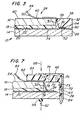
- Figure 3 is a view taken along line 3-3 of Figure 2.
- Figure 4 is a plan view of the mold fixture of the present invention.
- Figure 5 is an end view of the mold fixture taken along line 5-5 of Figure 4.
- Figure 6 is a view taken along line 6-6 of Figure 5.
- Figure 7 is a sectional section similar to that shown in Figure 3 taken along line 7-7 of Figure 4, with the mold fixture positioned at the notch area of the laminate, with portions removed for clarity.
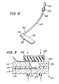
- Figure 8 is an isometric view of the connector used with the notch area.
- Figure 9 is a sectional view similar to Figure 7 of an alternate embodiment of the invention.
- the present invention is disclosed in combination with an antenna system for an automotive windshield. However, it should be appreciated that the present invention may be used in other applications where an opening or other cut-out area of a structure must be filled, and in particular in combination with other types of systems that require electrical connection to conductive elements within a notch area or other opening in a glass laminate.
- Figure 1 illustrates a laminated vehicle windshield 12 formed by outer and inner glass plies 14 and 16, respectively, which are bonded together by a plastic interlayer 18, preferably polyvinyl butyral.
- Plies 14 and 16 may be other transparent rigid materials, for example acrylic, polycarbonate, or the windshield 12 may include a combination of different transparent, rigid materials.
- Windshield 12 further includes at least one antenna element 20.
- the antenna element 20 is a transparent electroconductive coating applied on surface 22 of glass ply 14 in any manner well known in the art, and generally occupies the central portion of the windshield 12.
- the coating may be a single or multilayered metal containing coating, for example as disclosed in U.S.
- antenna element 20 may have a configuration different from that shown in Figure 1.
- element 20 may be T-shaped as shown in U.S. Patent 5,083,135 or may include multiple antenna elements having various shapes that are either directly or indirectly electrically interconnected.
- antenna element 20 may be a nontransparent electroconductive material, for example silver-containing ceramic paint, wires, metal foil, etc.
- the antenna may include a combination of coating, wire and/or ceramic antenna elements.
- antenna element 20 in this particular configuration is basically quadrilateral in shape and preferably spaced from the peripheral edge of the windshield 12.
- the exact shape and position of element 20, as well as any additional antenna elements depends in part on the design of the vehicle into which the windshield 12 is installed, the angle of windshield installation, the coating resistivity, the type of signal to be transmitted or received and the desired performance of the antenna. These types of design considerations for a transparent glass antenna are discussed in U.S. Patents 4,768,037; 4,849,766 and 5,083,135.
- a connector 24 provides a connection between the antenna element 20 and an electromagnetic energy transmitting and/or receiving device 26 (shown only in Figure 1) and is fixed to the windshield 12, as will be discussed later in more detail.
- Device 26 may be a radio, cellular phone, television, global positioning system or any other type of system that uses antenna element 20 to transmit and/or receive signals.
- the connector 24 is positioned along the upper edge 28 of the windshield 12.
- the connection arrangement between the connector 24 and antenna element 20 is configured such that the connector 24 is not laminated between plies 14 and 16. In this manner, the problem of entrapped air resulting from a connector being laminated within the windshield 12 is eliminated.
- a notch area 30 is cut out of the inner ply 16 along the upper edge 28 of the windshield 12, as shown in Figures 1-3.
- a corresponding section of the interlayer 18 is removed from the notch area 30.
- Connector 24 is adhered to a portion of the antenna element 20 that extends into the notch area 30 and the notch area 30 is filled with a sealant material 32 to further secure the connector 24 in place and seal the notch area 30, as will be discussed later in more detail.
- the antenna and notch area configuration are such that a portion of antenna element 20 passes through the notch area 30, the connector 24 is secured directly to element 20.
- the antenna element 20 may include an extension 34 which extends the antenna element 20 into the notch area 30 and provides an arrangement whereby the connector 24 may be electrically coupled to the antenna element 20.
- the extension 34 may be made of the same material as element 20. It is preferred that the element 20 or extension 34 should not extend to the edge 28 of the windshield 12 at notch area 30 but rather terminate at least 1 mm from the edge 28 to ensure that the electroconductive antenna elements are completely sealed within the notch area 30 by sealant 32 to inhibit degradation of the antenna element along edge 28.
- Connector 24 is preferably fabricated from stainless steel, copper, tin, brass or any other electroconductive material. If required, combinations of materials, such as stainless steel or brass coated with copper, tin or silver, may be used to enhance conductivity, strength and chemical durability.
- connector 24 includes a pad section 36 which overlays and is in electrical contact with a portion of extension 34 of antenna element 20, a section 38 along one edge of the pad 36, and an insulated connecting wire 40 which is secured to section 38.
- Section 38 is positioned along an edge of pad 36 so as to provide an unobstructed upper surface along which pressure may be applied to secure the connector 24 to extension 34.
- End 42 of wire 40 extends within section 38 and is secured thereto in any convenient manner, e.g.
- Connecting wire 40 includes a terminal assembly 44, e.g. a male JASO pin as shown in Figures 2 and 3 or other electrical connecting device well known in the art, connected to end 46 of wire 40 so that a coaxial cable 48 (shown only in Figure 1) from device 26 may be easily secured to connector 24.
- Wire 40 is insulated to prevent the connector 24 from contacting the vehicle in which windshield 12 is installed and adversely effecting the performance of the antenna.
- a nonconductive shrink-wrap cover 50 may be applied to assembly 44 near end 46 of wire 40 to further insulate the connector 24 and make it easier to handle assembly 44.
- an adhesive 52 is applied to section 36 to secure the connector 24 to antenna element 20 on outer glass ply 14.
- the electrical connection between the connector 24 and element 20 may be either a direct connection or a capacitive connection. More particularly, the adhesive 52 may be electrically conductive to provide a direct electrical connection between connector 24 and antenna element 20, or it may be electrically nonconductive so that the electrical connection is capacitive. It has been found that a capacitive connection may be used to produce a capacitive reactance that matches the inductive reactance of the antenna to the coaxial cable 48 (shown only in Figure 1) used to connect the antenna element 20 to the transmitting/receiving device 26, by minimizing the net reactive component as disclosed in U.S. Patent 5,355,144.
- the required surface area of the section 36 of the connector 24 is based in part, on the spacing between section 36 and antenna elements 20, i.e. the adhesive thickness, the types of materials used for the antenna element, connector and adhesive, and the desired type of connection, i.e. direct or capacitive. In instances where there is direct electrical connection between connector 24 and element 20, it may be desirable to have the surface area provided by pad section 36 large enough so that in the event a conductive adhesive 52 fails, the connector 24 may still maintain a capacitive connection that permits the continued operation of antenna element 20. If desired, colorants may be added to the adhesive 52 to hide the connector 24 when viewed through the outer surface of the windshield 12.
- the sections 36 and 38 of the connector 24 are preferably made from tin plated brass or tin plated stainless steel with a base metal thickness ranging from 0.002 to 0.02 in. (0.051 to 0.51 mm), and more preferably ranging from 0.005 to 0.007 in. (0.13 to 0.18 mm).
- Adhesive 52 may be a double-face tape, adhesive spray or any other type of adhesive system well known in the art.
- the connector 24 is positioned within the notch area 30 along the edge 28 of windshield 12.
- the notch area 30 must be large enough to accommodate the connector 24 as well as provide sufficient spacing between edge 54 of the connector 24 and edge 28 of the windshield 12 to ensure that the sealant 32 completely covers and seals connector 24 within the notch area 30 and provides a continuous moisture barrier along windshield edge 28 and notch edge 56.
- the spacing between connector edge 54 and windshield edge 28 should be at least 1 mm, and preferably at least 3 mm.
- the notch area 30 is filled with a non-conductive sealant 32 to protect and further secure the connector 24 in place, to seal the portion of the antenna element 20 within notch area 30 and to seal the exposed edge 56 of the notch area 30 by forming a moisture barrier.
- a non-conductive sealant 32 to protect and further secure the connector 24 in place, to seal the portion of the antenna element 20 within notch area 30 and to seal the exposed edge 56 of the notch area 30 by forming a moisture barrier.
- surface 58 of the sealant 32 align with surface 60 of inner glass ply 16 to provide a smooth, hard, uninterrupted surface along the marginal edge portion of the inner major surface of the windshield 12. This smooth surface quality along the sealant 32 in the notch area 30 is provided by a mold fixture, which will discussed later in more detail.
- the sealant 32 is preferably a room temperature curable material that may be injected into the notch area 30 and provide a hard surface when cured, preferably a Shore A hardness of at least about 85. Furthermore, the sealant 32 should not adversely effect the materials forming the antenna element 20 or extension 34 in a manner that will electrically isolate the connector 24 from the antenna.
- Sealants that have been used to fill and seal the notch area 30 include room temperature curable epoxies, such as Plastilok® 421 epoxy available from BF Goodrich, Adhesives Systems Division, Akron, Ohio and Scotch-Weld® DP-110 epoxy available from 3M Industrial Tape and Specialty Division, St. Paul, Minnesota, both of which are two-part flexible epoxy sealants.
- a mold fixture is used to enclose the notch area 30 and shape the sealant 32 during the notch filling and curing operation.
- mold fixture 62 is secured along edge 28 of the windshield 12 overlaying the notch area 30 and portions of glass surface 60, forming an enclosed cavity 63 which will be filled with sealant 32, as will be discussed later.
- the fixture 62 includes a resilient mold 64 and rigid backing plate 66.
- Mold 64 is preferably made of a material that will not stick to the sealant 32 and will withstand elevated temperatures of up to 200-350°F (93-177°C) without adversely affecting the mold, for reasons to be discussed later.
- the surface of mold 64 overlaying the windshield 12 and notch area 30 should have a smooth finish, which not only results in the filled notch having a smooth finish but also makes it is easier to remove the mold fixture 62 from the cured sealant.
- the mold surface 70 should also be resilient so that it may seal flush against portions of surface 60 and conform to any irregularities. However, the mold surface should not be so soft that it looses its shape as the sealant 32 is injected into cavity 63 through inlet 74 of the mold 64 to fill the notch area 30, as will be discussed later in more detail. It is preferred that the mold have a Shore A hardness of about 50-70, preferably 55-65.
- the mold 64 may be made of Silastic® M RTV rubber available from Dow Corning Corp., Midland, Ml. This mold material is a two component silicone rubber that provides a Shore A hardness of about 55-57 and a smooth surface quality. As an alternative to constructing the entire mold 64 of a singlew material, it is contemplated that the mold 64 may include a more rigid base material and just the surface of the mold 64 which contacts the windshield 12 and overlays the notch area 30 be constructed from a resilient with the desired hardness.
- mold 64 includes a main section 68, with a generally flat surface 70 that overlays notch area 30 and portions of glass surface 60, and a lip section 72 with a surface 73 that extends along edge 28 of windshield 12 to seal the notch area 30.
- Section 68 includes a sealant inlet 74 and vent holes 76.
- inlet 74 includes a chamber 77 which extends partially but not completely through section 68. The remaining thickness of the mold portion 68 is slit from the chamber 77 to mold surface 70. As a nozzle (not shown) is inserted into inlet 74 to inject sealant 32 into the notch area 30, slit 78 is forced open.
- the nozzle When the notch area is filled, the nozzle is removed and slit 78 closes to maintain the sealant within the notch area 30 as it cures.
- the closed slit 78 provides a smooth surface along mold surface 70, resulting in a corresponding smooth notch area surface 58.
- Mold 64 also includes a groove 80 which extends from edge 82 along the mold surface 70.
- Groove 80 is sized to receive a portion of wire 40 of connector 24 during the notch area filling operation and hold it along the windshield 12 so that section 68 of mold 64 may be seated flush against surface 60 of glass ply 16.
- sealant flows into groove 80 adhering a portion of wire 40 to surface 60. This arrangement reduces the possibility of connection 24 interfering with a windshield adhesive application and mounting system (not shown) which applies a bead of adhesive about the marginal edge of the windshield 12 along surface 60.
- the depth of the notch area 30 may be increased to move the connector 24 further inward from edge 28 of the windshield 12 a sufficient distance such that wire 40 is spaced from any adhesive that is subsequently applied about the marginal edge portion or periphery of the windshield 12 to hold the windshield in place in a vehicle.
- Backing plate 66 provides rigidity to the mold fixture 62 and maintains the mold shape during the notch filling operation. In addition, backing plate 66 distributes the pressure applied to selected portions of the mold fixture 62 when it is secured to windshield 12. Referring to Figure 5, portion 84 of plate 66 is folded over lip 72 of the mold 64 to seal the fixture 62 against windshield edge 28 and ensure that sealant 32 does not leak from the notch area 30 during the notch filling and subsequent curing operation. In the particular embodiment of the mold fixture 62 illustrated in Figures 4-6, plate 66 also includes tabs 86 which are received within corresponding cavities of section 68 to hold mold 64 and backing plate 66 together and prevent large deflection in the mold 64 when fixture 62 is secured to the windshield 12.
- Fixture 62 is secured to windshield 12 in any convenient manner.
- fixture 62 is clamped to windshield 12 by applying a force (indicated by arrow 88 in Figure 7) to backing plate 66 along a line slightly outboard of the notch area 30 and a corresponding force along glass ply 14 (indicated by arrow 92 in Figure 7).
- This later force is preferably applied through a rubber gasket 94 or other resilient material so as to distribute the force and avoid glass breakage. Concentrating the forces in these areas ensures a good seal between the fixture 62 and windshield 12 along the notch area 30.
- the mold fixture 62 may be secured to a clamping arrangement, e.g.
- One or more cavities may also be provided along that portion of surface 70 which overlays surface 60 of glass ply 16 and a vacuum may be drawn through the cavities to further secure the mold fixture 62 to the windshield 12.
- Backing plate 66 may be made of any rigid material that will distribute the clamping forces along the mold fixture 62. Although not limiting in the present invention, in one embodiment, plate 66 was a 0.080 inch (2.03 mm) thick aluminum plate.
- the antenna element 20 was a transparent, electroconductive multilayered coating centered on surface 22 of glass ply 14 within the main viewing area of the windshield 12 and having a resistivity of approximately 3 ohms per square.
- the distance from the edge of the antenna element coating to the edge of the windshield 12 varied, with a minimum spacing between the main portion of the coating forming antenna element 20 and the metal frame (not shown) surrounding the windshield 12 of 0.25 inches (6.4 mm).
- An extension 34 was used to bridge the space between the antenna element 20 and the notch area 30 as shown in Figures 1 and 2.
- the notch area be located in the central portion of the windshield 12, i.e. within the central third of the windshield 12 and more preferably at the center of windshield 12.
- Extension 34 was a coating identical to and applied at the same time as the antenna element 20. Extension 34 was 1 in. (25.4 mm) wide to accommodate the full width of pad section 36 of the connector 24, which is discussed below. In this particular embodiment of the antenna, edge 90 of extension 34 was spaced approximately 0.55 inches (14 mm) from edge 28 of the windshield to prevent electrical coupling of the metal coating to the underlying vehicle frame through the urethane adhesive used to secure the windshield 12 into the opening in the vehicle. It is believed that this electrical coupling will adversely affect the performance of the antenna.
- the notch area 30 was approximately 1.06 in. (27 mm) deep and 3.94 in. (150 mm) wide. Mold portion 68 was approximately 2.5 in. by 6.5 in. by 0.438 in.
- Sections 36 and 38 of connector 24 were a tin plated brass member approximately 0.007 in. (0.178 mm) thick throughout. Section 36 was approximately 0.31 x 0.79 in. (8 x 20 mm) and positioned so that it is completely on the extension 34 and there was a minimum of 0.59 inches (15 mm) between edge 54 of section 36 and edge 28 of the windshield 12. Wire 40 was a 20 gauge insulated wire with a JASO pin secured to end 46. Section 36 was secured to extension 34 by a double-sided electrically conductive adhesive tape approximately 0.002 in. (0.051 mm) thick, for example product no. CD-9082 tape, available from Specialty Tapes, WI, to make a direct electrical connection. As an alternative, an electrically nonconductive adhesive, for example Product No. 9482, available from 3M Company may be used to secure section 36 to the extension 34 (or element 20) and form a capacitive connection.
- an electrically nonconductive adhesive for example Product No. 9482, available from 3M Company may be used to secure
- the notch area 30 was filed with Scotch-Weld DP-110 epoxy.
- This particular sealant was modified by adding silane, e.g. Dow Corning® Z-6040 silane, available from Dow Corning, Midland, Michigan to the epoxy resin component in an amount equal to approximately 0.2-8 wt.% of the resin, and preferably 0.5-2 wt.%, to improve bonding of the sealant to the glass.
- silane e.g. Dow Corning® Z-6040 silane
- carbon black for example ArospereTM 11V carbon black available from J.M. Huber Corporation, Borger, Texas, was added to "hide” the filled notch by providing a black appearance consistent with a black ceramic border (not shown) which is typically applied about the marginal edge portion of an automotive vehicle windshield.
- the carbon black was added to the accelerator component in an amount equal to approximately 1-1.5 wt.% of the accelerator.
- the sealant was applied using a static mix applicator that mixed equal amounts of the two-part epoxy immediately prior to its injection into the notch area 30. As applied, the sealant sets up in about 15 minutes so that it could be handled more easily.
- the epoxy has a Shore A hardness of about 88.
- W041696 T1 Black which is a two part structural adhesive available from Advanced Polymer Concepts, Germantown, WI, may also be used. This later material provides a Shore A hardness of about 95
- the transparent electroconductive coating was applied to glass ply 14 in any manner well known in the art, using a mask to provide the desired antenna pattern.
- the entire surface 22 of ply 14 may be coated and thereafter selected portions of the coating removed to provide the desired antenna pattern.
- ply 14 was combined with ply 16, which includes the cut-out area corresponding to notch area 30, and the two plies were shaped simultaneously using techniques well known in the art, for example gravity sag bending. If desired, plies 14 and 16 may be shaped individually and/or prior to applying the antenna element 20.
- the interlayer 18 was inserted between plies 14 and 16 with a cut out section in the interlayer corresponding to the notch area 30.
- the entire assembly was then deaired and laminated using techniques well known in the art, to form a unitary structure.
- the notch area 30 was wiped clean and pad section 36 of connector 24 was secured to extension 34.
- Mold fixture 62 was then placed over the notch area 30 with wire 40 extending from the mold 64 through groove 80 and clamped in place.
- the sealant 32 was then injected through inlet 74 of the mold 64 into the notch area 30. After filling, the sealant 32 was allowed to set and cure for about 20 minutes to achieve a desired surface hardness before the mold fixture 62 was removed.
- the cure time for the sealant may be reduced by heating the mold fixture 62 and/or heating the notch area 30 before, during, and/or after filling to a temperature of about 200-350°F (73-177°C). For this reason, if heating is used to accelerate curing, the mold material must be able to withstand these elevated temperatures.
- the sealant 32 itself may be heated during the notch filling operation to reduce its viscosity and reduce its cure time. Care should be taken in heating the sealant to ensure that it is not heated to too high of a temperature, resulting in the chemical breakdown of the sealant.
- the mold fixture 62 is used to seal an electrical connection made at a notch area 30 positioned along an edge of the windshield 12.
- the teachings of the present invention may also be used to seal a connection made at an opening in the windshield spaced from its edge. More specifically, referring to Figure 9, glass ply 116 includes a hole 130 within its periphery which is positioned to overlay electroconductive extension 134 on glass ply 114 of windshield 112. A corresponding hole 110 is formed in interlayer 118. A connector 124 is positioned within the hole 130 and secured to the extension 134.
- a mold fixture 162 having a resilient mold 164 and backing plate 166, similar to that discussed earlier may be secured to the windshield 112 in any convenient manner to cover the hole 130. Sealant (not shown) could then be injected through the mold fixture 162 to seal the hole 130 and further secure the connector 124 in place.
Landscapes
- Engineering & Computer Science (AREA)
- Mechanical Engineering (AREA)
- Chemical & Material Sciences (AREA)
- Composite Materials (AREA)
- Details Of Aerials (AREA)
- Moulds For Moulding Plastics Or The Like (AREA)
- Injection Moulding Of Plastics Or The Like (AREA)
Claims (19)
- Dispositif de moulage (62) pour remplir une ouverture (30) dans un feuilleté (12) et former un joint (32) utilisé pour remplir ladite ouverture (30),
comprenant :un moule (64) possédant des surfaces souples de contact (70, 73) de joint et une surface opposée,au moins un orifice d'entrée (74) de jointau moins un évent (76), etune plaque de support (66) fixée audit moule (64) et recouvrant des portions déterminées de ladite surface opposée. - Dispositif de moulage (62) selon la revendication 1 dans lequel lesdites surfaces souples (70, 73) dudit moule (64) possèdent une dureté Shore A d'environ 50 à 70.
- Dispositif de moulage (62) selon la revendication 2 dans lequel lesdites surfaces souples (70, 73) dudit moule (64) possèdent une dureté Shore A de 55 à 65.
- Dispositif de moulage (62) selon la revendication 3 dans lequel ledit moule (64) est constitué de caoutchouc silicone.
- Dispositif de moulage (62) selon la revendication 1 dans lequel la première surface souple (70) comprend une gorge (80) dont les dimensions sont prévues pour recevoir un élément conducteur de l'électricité (40) s'étendant depuis l'intérieur de ladite ouverture (30).
- Dispositif de moulage (62) selon la revendication 1 dans lequel ledit orifice d'entrée (74) et ledit évent (76) s'étendent au travers d'une première section (68) dudit moule (64).
- Dispositif de moulage (62) selon la revendication 1 comprenant en outre des moyens pour assujettir ledit dispositif de moulage (62) audit feuilleté (12).
- Dispositif de moulage (62) selon la revendication 7 dans lequel lesdits moyens d'assujettissement comprennent des moyens pour appliquer une pression à des portions déterminées de ladite plaque de support (66) pour compresser ledit moule (64) et assujettir ledit dispositif de moulage (62) audit feuilleté (12).
- Dispositif de moulage (62) selon la revendication 1 dans lequel ladite surface souple de contact (70) est une première surface souple de contact de joint d'une première section (68) dudit moule (64) et ladite surface opposées est une première surface opposée de ladite première portion (68) et ledit moule (64) comprend en outre une seconde section (72) s'étendant sensiblement perpendiculairement à ladite première section (68), ladite seconde section (72) possédant une seconde surface souple de contact (73) de joint s'étendant depuis ladite première surface souple (70) et une seconde surface opposée, dans lequel ladite plaque de support (66) recouvre des portions déterminées desdites première et seconde surfaces opposées.
- Dispositif de moulage (62) selon la revendication 9 dans lequel ledit moule (64) est constitué de caoutchouc silicone, les surfaces souples (70, 73) possédant une dureté Shore A d'environ 50 à 70, lesdits orifice d'entrée (74) et évent (76) s'étendant au travers de ladite première section (68) dudit moule (64), et de moyens pour fixer ladite dispositif de moulage (62) audit feuilleté (12).
- Procédé d'obturation d'une ouverture (30) dans un vitrage feuilleté (12), ledit feuilleté (12) comprenant une première feuille (16) à travers lequel s'étend ladite ouverture (30) et une seconde feuille (14) laminée avec ladite première feuille (16), comprenant les étapes de :positionner une dispositif de moulage (62) comprenant un moule (64) ayant des surfaces souples de contact de joint (70, 73) sur ledit feuilleté (12) de sorte que des portions déterminées dudit moule (64) recouvrent ladite ouverture (30) et que les portions restantes dudit moule (64) recouvrent des portions déterminées dudit feuilleté (12) directement adjacentes à ladite ouverture (30), dans lequel lesdits moules (64) et feuilleté (12) délimitent entreeux une cavité (63) ;assujettir ledit dispositif de moulage (62) audit feuilleté (12) de sorte que ladite ouverture (30) est scellée contre lesdites surfaces souples (70, 73) du moule ;injecter un joint (32) dans ladite cavité (63) pour obturer ladite ouverture (30) ;permettre audit joint (32) de durcir et d'atteindre une dureté désirée ; et retirer ledit dispositif de moulage (62) dudit feuilleté (12).
- Procédé selon la revendication 11 dans lequel ladite étape d'assujettissement comprend l'étape d'appliquer une force sur des portions déterminées dudit moule (64) qui recouvrent ladite première feuille (16) pour presser ledit moule (64) contre ledit feuilleté (12) et compresser lesdites portions déterminées dudit moule (64) de sorte à maintenir ledit moule (64) en place.
- Procédé selon la revendication 12 dans lequel ladite étape d'assujettissement comprend l'étape d'appliquer ledit dispositif de moulage (62) sur ledit feuilleté (12).
- Procédé selon la revendication 11 comprenant en outre l'étape de chauffer ledit joint (32) avant ladite étape d'injection pour accélérer ledit durcissement dudit joint (32).
- Procédé selon la revendication 11 comprenant en outre l'étape de chauffer ledit moule (64) avant ladite étape de positionnement pour accélérer ledit durcissement dudit joint (32).
- Procédé selon la revendication 11 comprenant en outre l'étape de chauffer lesdits moule (64) et joint (32) après ladite étape d'injection pour accélérer ledit durcissement dudit joint (32).
- Procédé selon la revendication 11 comprenant en outre l'étape de fixation d'un connecteur électrique (40) à l'intérieur de ladite ouverture (30) avant ladite étape de positionnement.
- Procédé selon la revendication 11 dans lequel ladite ouverture (30) est formée le long d'un bord de ladite feuille (16) et ladite étape de positionnement comprend l'étape de positionner ledit moule souple (64) au dessus de ladite ouverture (30) de sorte que des premières portions dudit moule (64) s'étendent le long de portions déterminées d'une surface principale dudit feuilleté (12) directement adjacente à ladite ouverture (30) et des secondes portions dudit moule (64) s'étendent le long de portions déterminées d'un bord (28) dudit feuilleté (12) directement adjacent de ladite ouverture (30), dans lequel lesdits moule (64) et feuilleté (12) délimitent entre eux ladite cavité (63).
- Procédé selon la revendication 18 dans lequel ladite étape d'assujettissement comprend l'étape d'appliquer ledit dispositif de moulage (62) sur ledit feuilleté (12).
Applications Claiming Priority (2)
| Application Number | Priority Date | Filing Date | Title |
|---|---|---|---|
| US713915 | 1991-06-12 | ||
| US08/713,915 US5902536A (en) | 1996-09-13 | 1996-09-13 | Method for sealing an electrical connection to a laminated transparency |
Publications (3)
| Publication Number | Publication Date |
|---|---|
| EP0835743A2 EP0835743A2 (fr) | 1998-04-15 |
| EP0835743A3 EP0835743A3 (fr) | 2000-01-26 |
| EP0835743B1 true EP0835743B1 (fr) | 2002-08-14 |
Family
ID=24868059
Family Applications (1)
| Application Number | Title | Priority Date | Filing Date |
|---|---|---|---|
| EP97115403A Expired - Lifetime EP0835743B1 (fr) | 1996-09-13 | 1997-09-05 | Dispositif et procédé pour fixer une connexion électrique à un article transparent stratifié |
Country Status (7)
| Country | Link |
|---|---|
| US (1) | US5902536A (fr) |
| EP (1) | EP0835743B1 (fr) |
| JP (1) | JP3208361B2 (fr) |
| KR (1) | KR100259727B1 (fr) |
| CA (1) | CA2212580C (fr) |
| DE (1) | DE69714678T2 (fr) |
| ES (1) | ES2184945T3 (fr) |
Families Citing this family (19)
| Publication number | Priority date | Publication date | Assignee | Title |
|---|---|---|---|---|
| WO2007057463A1 (fr) * | 2005-11-21 | 2007-05-24 | Agc Flat Glass Europe Sa | Vitrage feuilleté et procédé de fabrication d'un vitrage feuilleté |
| WO2009001264A1 (fr) * | 2007-06-27 | 2008-12-31 | Koninklijke Philips Electronics N.V. | Dispositif d'émission de lumière |
| FR2921520B1 (fr) * | 2007-09-20 | 2014-03-14 | Saint Gobain | Element de connexion electrique et vitrage pourvu d'un tel element |
| DE102008030101A1 (de) * | 2007-12-11 | 2009-06-25 | Saint-Gobain Sekurit Deutschland Gmbh & Co. Kg | Lötanschlusselement |
| US8377368B2 (en) * | 2009-12-11 | 2013-02-19 | Ti Automotive Technology Center Gmbh | Component mounting arrangement |
| FR2965641B1 (fr) * | 2010-10-04 | 2013-10-11 | Saint Gobain | Vitrage multiple a diffusion variable par cristaux liquides, son procede de fabrication |
| CA2835381C (fr) | 2011-05-10 | 2018-11-06 | Saint-Gobain Glass France | Vitre munie d'un element de raccordement electrique |
| FR2985328B1 (fr) * | 2011-12-29 | 2013-12-20 | Saint Gobain | Vitrage multiple a diffusion variable par cristaux liquides |
| FR2996802B1 (fr) | 2012-10-12 | 2014-11-21 | Saint Gobain | Vitrage feuillete |
| KR101412971B1 (ko) * | 2013-05-21 | 2014-06-27 | 위너콤 주식회사 | 수밀구조를 향상시킨 차량용 lf 안테나의 제조방법 및 그에 따라 수밀구조를 향상시킨 차량용 lf 안테나 장치 |
| JP6211823B2 (ja) * | 2013-06-20 | 2017-10-11 | 日本板硝子株式会社 | 自動車用ウインドウガラス及びその製造方法 |
| CN104476855B (zh) * | 2014-12-01 | 2016-01-20 | 福耀玻璃工业集团股份有限公司 | 一种带孔的夹层玻璃 |
| DE102016103745B4 (de) * | 2016-03-02 | 2019-03-14 | Webasto SE | Formwerkzeug zum Fixieren eines Einsatzes in einer Ausnehmung eines tafelartigen Werkstücks sowie Fahrzeugdachelement |
| CO2017007600A1 (es) * | 2017-03-31 | 2018-01-31 | Agp America Sa | Laminado para automotor con ventana superior para cámara |
| US10083885B1 (en) * | 2017-06-06 | 2018-09-25 | Cree, Inc. | Multi-layer potting for electronic modules |
| WO2019186512A1 (fr) * | 2018-03-30 | 2019-10-03 | Agp America S.A. | Stratifié automobile doté de trous |
| CN110254743B (zh) * | 2019-05-17 | 2023-06-23 | 陕西飞机工业(集团)有限公司 | 一种驾驶舱侧风挡玻璃装配方法及装配骨架 |
| EP4043255B1 (fr) * | 2021-02-11 | 2024-11-27 | Inalfa Roof Systems Group B.V. | Panneau de toit transparent comportant une unité centrale isolée |
| US12311637B2 (en) | 2022-11-04 | 2025-05-27 | Agc Automotive Americas Co. | Laminated glazing assembly including an antenna assembly |
Family Cites Families (16)
| Publication number | Priority date | Publication date | Assignee | Title |
|---|---|---|---|---|
| US3655545A (en) * | 1968-02-28 | 1972-04-11 | Ppg Industries Inc | Post heating of sputtered metal oxide films |
| US3962488A (en) * | 1974-08-09 | 1976-06-08 | Ppg Industries, Inc. | Electrically conductive coating |
| US3987449A (en) * | 1975-04-11 | 1976-10-19 | Ppg Industries, Inc. | Antenna windshield |
| DE3402518C2 (de) * | 1984-01-26 | 1986-01-02 | VEGLA Vereinigte Glaswerke GmbH, 5100 Aachen | Verbundglasscheibe mit einem in der thermoplastischen Zwischenschicht angeordneten Draht und wenigstens einem Anschlußkabel, sowie Verfahren zu ihrer Herstellung |
| GB2193846B (en) * | 1986-07-04 | 1990-04-18 | Central Glass Co Ltd | Vehicle window glass antenna using transparent conductive film |
| US4707700A (en) * | 1986-07-25 | 1987-11-17 | General Motors Corporation | Vehicle roof mounted slot antenna with lossy conductive material for low VSWR |
| GB2200498B (en) * | 1986-12-19 | 1990-07-18 | Central Glass Co Ltd | Vehicle window glass antenna using transparent conductive film |
| US4898789A (en) * | 1988-04-04 | 1990-02-06 | Ppg Industries, Inc. | Low emissivity film for automotive heat load reduction |
| US5213828A (en) * | 1989-07-03 | 1993-05-25 | Ppg Industries, Inc. | Heatable windshield |
| US5135694A (en) * | 1989-11-10 | 1992-08-04 | Seiko Epson Corporation | Electronic device wristband |
| US5083135A (en) * | 1990-11-13 | 1992-01-21 | General Motors Corporation | Transparent film antenna for a vehicle window |
| US5416491A (en) * | 1992-01-31 | 1995-05-16 | Central Glass Company, Limited | Automotive window glass antenna |
| US5355144A (en) * | 1992-03-16 | 1994-10-11 | The Ohio State University | Transparent window antenna |
| FR2703838B1 (fr) * | 1993-04-08 | 1995-06-09 | Saint Gobain Vitrage Int | Vitrage muni d'un element de connexion. |
| GB9318563D0 (en) * | 1993-09-07 | 1993-10-20 | Splintex Belge Sa | A laminated glazing assembly and a method and apparatus for forming such an assembly |
| US5620648A (en) * | 1995-11-30 | 1997-04-15 | Essex Specialty Products, Inc. | Process for the preparation of prefabricated vehicle windows |
-
1996
- 1996-09-13 US US08/713,915 patent/US5902536A/en not_active Expired - Fee Related
-
1997
- 1997-08-22 CA CA002212580A patent/CA2212580C/fr not_active Expired - Fee Related
- 1997-09-05 EP EP97115403A patent/EP0835743B1/fr not_active Expired - Lifetime
- 1997-09-05 DE DE69714678T patent/DE69714678T2/de not_active Expired - Fee Related
- 1997-09-05 ES ES97115403T patent/ES2184945T3/es not_active Expired - Lifetime
- 1997-09-12 KR KR1019970046982A patent/KR100259727B1/ko not_active Expired - Fee Related
- 1997-09-12 JP JP24883497A patent/JP3208361B2/ja not_active Expired - Fee Related
Also Published As
| Publication number | Publication date |
|---|---|
| EP0835743A2 (fr) | 1998-04-15 |
| EP0835743A3 (fr) | 2000-01-26 |
| CA2212580A1 (fr) | 1998-03-13 |
| DE69714678D1 (de) | 2002-09-19 |
| US5902536A (en) | 1999-05-11 |
| MX9706936A (es) | 1998-03-31 |
| DE69714678T2 (de) | 2003-04-10 |
| JPH10175220A (ja) | 1998-06-30 |
| JP3208361B2 (ja) | 2001-09-10 |
| CA2212580C (fr) | 2000-10-24 |
| ES2184945T3 (es) | 2003-04-16 |
| KR19980024572A (ko) | 1998-07-06 |
| KR100259727B1 (ko) | 2000-06-15 |
Similar Documents
| Publication | Publication Date | Title |
|---|---|---|
| EP0835743B1 (fr) | Dispositif et procédé pour fixer une connexion électrique à un article transparent stratifié | |
| CA2184193C (fr) | Antenne sur verre et son dispositif de connexion | |
| EP0780927B1 (fr) | Dispositif de connexion pour antenne | |
| CA2163812C (fr) | Antenne en materiau de verre, a installer dans glace de vehicule automobile | |
| CA2979604C (fr) | Vitrage a antenne pour vehicule | |
| KR20010052871A (ko) | 투명 안테나 및 그 제조 방법 | |
| US5099104A (en) | Electrically heatable laminated glass plates having an electrically conductive surface coating | |
| JPH10224137A (ja) | インピーダンス整合ネットワークを有するガラスアンテナ装置 | |
| ZA200401942B (en) | Method for making a plastic pane with electrical conductor structure and plastic pane with embedded wires. | |
| CA2942938A1 (fr) | Panneau transparent dote d'un revetement chauffant | |
| EP4244933B1 (fr) | Système d'antenne | |
| EP2063685A1 (fr) | Vitrage en matière plastique | |
| US12187010B2 (en) | Glass structure, adhesive structure, and method for producing glass structure | |
| MXPA97006936A (en) | Apparatus and method for sealing an electrical connection to a lamin transparent sheet | |
| GB2281683A (en) | A laminated glazing assembly and a method and apparatus for forming such an assembly | |
| JP3075633U (ja) | ガラスアンテナ | |
| EP0435144A1 (fr) | Joint d'étanchéité pour pare-brise chauffant | |
| CN120156263B (zh) | 车窗玻璃组件和车辆 | |
| MXPA00012110A (en) | On-glass antenna |
Legal Events
| Date | Code | Title | Description |
|---|---|---|---|
| PUAI | Public reference made under article 153(3) epc to a published international application that has entered the european phase |
Free format text: ORIGINAL CODE: 0009012 |
|
| AK | Designated contracting states |
Kind code of ref document: A2 Designated state(s): BE DE ES FR GB IT NL |
|
| AX | Request for extension of the european patent |
Free format text: AL;LT;LV;RO;SI |
|
| RAP1 | Party data changed (applicant data changed or rights of an application transferred) |
Owner name: PPG INDUSTRIES OHIO, INC. |
|
| PUAL | Search report despatched |
Free format text: ORIGINAL CODE: 0009013 |
|
| AK | Designated contracting states |
Kind code of ref document: A3 Designated state(s): AT BE CH DE DK ES FI FR GB GR IE IT LI LU MC NL PT SE |
|
| AX | Request for extension of the european patent |
Free format text: AL;LT;LV;RO;SI |
|
| 17P | Request for examination filed |
Effective date: 20000721 |
|
| AKX | Designation fees paid |
Free format text: DE FR GB IT |
|
| RBV | Designated contracting states (corrected) |
Designated state(s): BE DE ES FR GB IT NL |
|
| 17Q | First examination report despatched |
Effective date: 20010425 |
|
| GRAG | Despatch of communication of intention to grant |
Free format text: ORIGINAL CODE: EPIDOS AGRA |
|
| GRAG | Despatch of communication of intention to grant |
Free format text: ORIGINAL CODE: EPIDOS AGRA |
|
| GRAH | Despatch of communication of intention to grant a patent |
Free format text: ORIGINAL CODE: EPIDOS IGRA |
|
| GRAH | Despatch of communication of intention to grant a patent |
Free format text: ORIGINAL CODE: EPIDOS IGRA |
|
| GRAA | (expected) grant |
Free format text: ORIGINAL CODE: 0009210 |
|
| AK | Designated contracting states |
Kind code of ref document: B1 Designated state(s): BE DE ES FR GB IT NL |
|
| REG | Reference to a national code |
Ref country code: GB Ref legal event code: FG4D |
|
| REF | Corresponds to: |
Ref document number: 69714678 Country of ref document: DE Date of ref document: 20020919 |
|
| PGFP | Annual fee paid to national office [announced via postgrant information from national office to epo] |
Ref country code: DE Payment date: 20020930 Year of fee payment: 6 |
|
| PGFP | Annual fee paid to national office [announced via postgrant information from national office to epo] |
Ref country code: ES Payment date: 20021009 Year of fee payment: 6 |
|
| ET | Fr: translation filed | ||
| REG | Reference to a national code |
Ref country code: ES Ref legal event code: FG2A Ref document number: 2184945 Country of ref document: ES Kind code of ref document: T3 |
|
| PLBE | No opposition filed within time limit |
Free format text: ORIGINAL CODE: 0009261 |
|
| STAA | Information on the status of an ep patent application or granted ep patent |
Free format text: STATUS: NO OPPOSITION FILED WITHIN TIME LIMIT |
|
| 26N | No opposition filed |
Effective date: 20030515 |
|
| PGFP | Annual fee paid to national office [announced via postgrant information from national office to epo] |
Ref country code: NL Payment date: 20030825 Year of fee payment: 7 |
|
| PGFP | Annual fee paid to national office [announced via postgrant information from national office to epo] |
Ref country code: GB Payment date: 20030827 Year of fee payment: 7 |
|
| PG25 | Lapsed in a contracting state [announced via postgrant information from national office to epo] |
Ref country code: ES Free format text: LAPSE BECAUSE OF NON-PAYMENT OF DUE FEES Effective date: 20030906 |
|
| PGFP | Annual fee paid to national office [announced via postgrant information from national office to epo] |
Ref country code: FR Payment date: 20030918 Year of fee payment: 7 |
|
| PGFP | Annual fee paid to national office [announced via postgrant information from national office to epo] |
Ref country code: BE Payment date: 20031017 Year of fee payment: 7 |
|
| PG25 | Lapsed in a contracting state [announced via postgrant information from national office to epo] |
Ref country code: DE Free format text: LAPSE BECAUSE OF NON-PAYMENT OF DUE FEES Effective date: 20040401 |
|
| PG25 | Lapsed in a contracting state [announced via postgrant information from national office to epo] |
Ref country code: GB Free format text: LAPSE BECAUSE OF NON-PAYMENT OF DUE FEES Effective date: 20040905 |
|
| PG25 | Lapsed in a contracting state [announced via postgrant information from national office to epo] |
Ref country code: BE Free format text: LAPSE BECAUSE OF NON-PAYMENT OF DUE FEES Effective date: 20040930 |
|
| REG | Reference to a national code |
Ref country code: ES Ref legal event code: FD2A Effective date: 20030906 |
|
| BERE | Be: lapsed |
Owner name: *PPG INDUSTRIES OHIO INC. Effective date: 20040930 |
|
| PG25 | Lapsed in a contracting state [announced via postgrant information from national office to epo] |
Ref country code: NL Free format text: LAPSE BECAUSE OF NON-PAYMENT OF DUE FEES Effective date: 20050401 |
|
| GBPC | Gb: european patent ceased through non-payment of renewal fee |
Effective date: 20040905 |
|
| PG25 | Lapsed in a contracting state [announced via postgrant information from national office to epo] |
Ref country code: FR Free format text: LAPSE BECAUSE OF NON-PAYMENT OF DUE FEES Effective date: 20050531 |
|
| NLV4 | Nl: lapsed or anulled due to non-payment of the annual fee |
Effective date: 20050401 |
|
| REG | Reference to a national code |
Ref country code: FR Ref legal event code: ST |
|
| PG25 | Lapsed in a contracting state [announced via postgrant information from national office to epo] |
Ref country code: IT Free format text: LAPSE BECAUSE OF NON-PAYMENT OF DUE FEES;WARNING: LAPSES OF ITALIAN PATENTS WITH EFFECTIVE DATE BEFORE 2007 MAY HAVE OCCURRED AT ANY TIME BEFORE 2007. THE CORRECT EFFECTIVE DATE MAY BE DIFFERENT FROM THE ONE RECORDED. Effective date: 20050905 |
|
| BERE | Be: lapsed |
Owner name: *PPG INDUSTRIES OHIO INC. Effective date: 20040930 |