EP0835747A2 - Verfahren zum Transport eines Gürtelaufbaustreifens zum Aufbau eines Gürtels für einen Fahrzeugluftreifen - Google Patents
Verfahren zum Transport eines Gürtelaufbaustreifens zum Aufbau eines Gürtels für einen Fahrzeugluftreifen Download PDFInfo
- Publication number
- EP0835747A2 EP0835747A2 EP97117308A EP97117308A EP0835747A2 EP 0835747 A2 EP0835747 A2 EP 0835747A2 EP 97117308 A EP97117308 A EP 97117308A EP 97117308 A EP97117308 A EP 97117308A EP 0835747 A2 EP0835747 A2 EP 0835747A2
- Authority
- EP
- European Patent Office
- Prior art keywords
- belt
- strip
- tip
- side edge
- edge
- Prior art date
- Legal status (The legal status is an assumption and is not a legal conclusion. Google has not performed a legal analysis and makes no representation as to the accuracy of the status listed.)
- Withdrawn
Links
Images


Classifications
-
- B—PERFORMING OPERATIONS; TRANSPORTING
- B29—WORKING OF PLASTICS; WORKING OF SUBSTANCES IN A PLASTIC STATE IN GENERAL
- B29D—PRODUCING PARTICULAR ARTICLES FROM PLASTICS OR FROM SUBSTANCES IN A PLASTIC STATE
- B29D30/00—Producing pneumatic or solid tyres or parts thereof
- B29D30/06—Pneumatic tyres or parts thereof (e.g. produced by casting, moulding, compression moulding, injection moulding, centrifugal casting)
- B29D30/38—Textile inserts, e.g. cord or canvas layers, for tyres; Treatment of inserts prior to building the tyre
- B29D30/44—Stretching or treating the layers before application on the drum
-
- B—PERFORMING OPERATIONS; TRANSPORTING
- B29—WORKING OF PLASTICS; WORKING OF SUBSTANCES IN A PLASTIC STATE IN GENERAL
- B29D—PRODUCING PARTICULAR ARTICLES FROM PLASTICS OR FROM SUBSTANCES IN A PLASTIC STATE
- B29D30/00—Producing pneumatic or solid tyres or parts thereof
- B29D30/06—Pneumatic tyres or parts thereof (e.g. produced by casting, moulding, compression moulding, injection moulding, centrifugal casting)
- B29D30/38—Textile inserts, e.g. cord or canvas layers, for tyres; Treatment of inserts prior to building the tyre
- B29D30/44—Stretching or treating the layers before application on the drum
- B29D2030/4406—Adjusting the positions of the layers
-
- B—PERFORMING OPERATIONS; TRANSPORTING
- B29—WORKING OF PLASTICS; WORKING OF SUBSTANCES IN A PLASTIC STATE IN GENERAL
- B29D—PRODUCING PARTICULAR ARTICLES FROM PLASTICS OR FROM SUBSTANCES IN A PLASTIC STATE
- B29D30/00—Producing pneumatic or solid tyres or parts thereof
- B29D30/06—Pneumatic tyres or parts thereof (e.g. produced by casting, moulding, compression moulding, injection moulding, centrifugal casting)
- B29D30/38—Textile inserts, e.g. cord or canvas layers, for tyres; Treatment of inserts prior to building the tyre
- B29D30/44—Stretching or treating the layers before application on the drum
- B29D2030/4406—Adjusting the positions of the layers
- B29D2030/4418—Adjusting the positions of the layers laterally, e.g. sideways
-
- B—PERFORMING OPERATIONS; TRANSPORTING
- B65—CONVEYING; PACKING; STORING; HANDLING THIN OR FILAMENTARY MATERIAL
- B65H—HANDLING THIN OR FILAMENTARY MATERIAL, e.g. SHEETS, WEBS, CABLES
- B65H2801/00—Application field
- B65H2801/93—Tyres
Definitions
- the invention relates to a method for transporting a Belt building strip for building a belt for one Pneumatic vehicle tires with parallel oblique to the conveying direction progressively arranged embedded in rubber Strength members, especially made of steel, into one downstream processing facility and Preparation of the belt construction strip for further processing in the downstream processing facility, e.g.
- a belt building drum the belt building strip, the across the conveying direction on both sides and through each a side edge on its front in the conveying direction and on its rear side in the counter-conveying direction each bounded by a leading edge or by a trailing edge is, which is essentially oblique parallel to reinforcements run so that the front edge with one side edge and the rear edge with the other side edge under each Inclusion of an acute angle of in particular 10 to 35 ° a front stripe tip or a rear stripe tip forms over at least two in a row in the conveying direction arranged, in particular circulating funding for Processing facility is promoted and doing so is aligned laterally without a side stop.
- the invention also relates to a device for conveying and for preparing a belt building strip for building a belt of a pneumatic vehicle tire with parallel oblique arranged in the direction of conveyance in rubber embedded strength members, in particular made of steel, for Further processing in a subordinate Processing device, in particular one Belt building drum, two in a row circulating funding are formed, at least of which the upstream funding is controlled is laterally displaceable.
- belt building strips for building a belt a pneumatic vehicle tire from parallel oblique to Conveying direction arranged in rubber train embedded steel cords and over rotating Convey conveyor belts to a belt building drum.
- the front end of the belt building drum fed Belt building strip is placed on the drum, which Belt building drum is rotated about its axis and the Belt construction strip once around the circumference of the Belt construction drum wound, so that the rear edge of the wound belt construction strip on the drum in Touch contact with the front edge of the belt building strip is coming.
- The are along their leading edge or trailing edge both ends of the belt construction strip without overlapping the Steel cords spliced together. Then will usually a second or further belt layer on the first belt layer applied in the same way.
- the belt building strips are designed so that the Steel cords already at an acute angle, for example, take 10 to 30 ° to the circumferential direction.
- the belt construction strips with side in essentially parallel side edges and one at an angle running front edge and with a sloping rear trailing edge formed so that the pointed Angle with the leading edge enclosing a side edge with this side edge a front essentially triangular Lace forms on which one through the two side edges laterally limited almost rectangular main part and in Connection to it including the acute angle to the other side edge aligned rear side edge with this side edge is a rearward triangular one Lace forms.
- This mounting strip is usually included its front tip ahead to the belt building drum promoted.
- the side edges of the formed from rubber and steel cord Belt building strips are usually for manufacturing reasons as well as from external forces during funding in their edges are not straight, but curvilinear, the curvilinearity of both side edges is different is designed to each other, so that also in the conveying direction running center line of symmetry between the side edges a curvilinear one running between the two side edges Represents curve.
- the two tips are usually also due to various external forces and because of the plastic deformability of the material often irregularly curved.
- the tips can both axially inwards as well as axially outwards or even below Change of direction be curved.
- the Belt building strips are usually made by one continuous belt construction belt with cut parallel to the oblique steel cords made so that when Cut the trailing edge of the previous one Belt construction strip or the leading edge of the following Belt construction strip is formed. Through the Cutting movement of the knife from one side edge to the other side edge, for example Rubber material pulled to the side so that the front and the back tip will be curved.
- This curvature can but also by other external forces during the Production of the belt construction strip or during the Funding to the belt building drum take place. For example are due to side edge stops or leading edge stops mechanical contact is a source of danger such curvatures.
- the two irregular thickness curves are irregularly formed irregularly, so that on Pneumatic vehicle tires in various circumferential positions different maximum thicknesses on one side and on generated on the other side, the Tire uniformity compromised.
- lateral guide rollers that can be adjusted together will also be the desired width format that the strip should take. This does make them Irregularities in the contour course straightened out over the set the side position of the guide rollers.
- Tips of a belt construction strip which is to the side are curved away from the belt construction strip, can with the restrictions and risks outlined above be aligned. Tips, however, axially inwards to the Belt construction strips are curved are not alignable.
- the first lever arm already comes either not in contact with the side edge or it will pivoted so far that he pointed the tip even further inwards bends.
- the second lever arm then swings inwards and immediately presses on the inward curved end of the Tip and finally squeezes the end portion of the tip together.
- the danger of the original curvature still intensified and possibly irreparably compressed is with such curvatures with a device according to US 4,769,104 cannot be ruled out.
- the device according to US 4,769,104 thus enables one limited alignment of side edges in the area of the Main part of a belt building strip and a limited one Alignment of the front edge of the belt construction strip.
- a certain predetermined contour of the side edge or one This does not lead to the tip of the belt construction strip adjustable. It is also not possible later, after the Alignment expected based on experience Deformations through targeted pre-deformations at the Alignment to take into account so that when the later deformations with the preset counteracting deformations and thus the desired shape is generated.
- the device includes a variety of individual ones mechanical parts, each with its own mechanical device for aligning the front tip and a facility for the independent alignment of the rear tip as well as separate mechanical devices for machining the main part.
- the variety of mechanical lateral forces also increase the Risk of lateral frictional contact with the Belt construction strips only further undesired deformations be generated.
- the invention is therefore based on the object of a method and to provide a device of the type mentioned at the outset, with which it is possible to build a belt construction strip Processing device, in particular one Belt building drum, feed so that the building strip is safer to process and the quality of the belt in the Pneumatic vehicle tires is improved.
- the object is achieved by the method according to the Features of claim 1 and by the device according to the Features of claim 10 solved.
- the lateral alignment without a side stop reduces the risk of side Effects on the side edge and thus the danger of undesired deformations. It also makes the Danger of material accumulation in the Side edge area, such as that of mechanical stops are largely avoided.
- a simple move of the irregularities in the course of the side edges Irregularities in the thickness of the side edge and thus problems with uniformity of the tire are eliminated.
- This is used for processing on a belt-building drum improves the spliceability.
- With the belt building drum ensures that the front and rear edge can be reliably spliced together, whereby the main part is also aligned.
- the quality of the This improves the belt in pneumatic vehicle tires.
- the procedure in the three steps enables one Alignment according to the different requirements for the tips and the main part, according to the Funding process, i.e. first the front part, then that Main part, then rear part aligned.
- the method according to the features of claim 2 enables throughout the funding, as long as Belt construction strip material in the detection area of the sensors is an exact determination of the actual position of the in Detection area located side edge sections, one Comparison with target values for the position of the in the conveying direction seen section of the belt assembly strip, which is in the Detection area of the sensors is located and through corresponding readjustment of the side edge position in Dependence on the determined deviations from actual and Setpoints an individual alignment according to the above the length of the belt construction strip different Conditions.
- the method according to the features of claim 3 enables a reliable, simple alignment of the Belt construction strip in the conveyor area. This will achieved that by the side edge related orientation of the front tip and the rear tip the front and the rear tip for further processing the actual Requirements for the most precise possible further processing accordingly in their side edge position and in their shape the lateral position desired for further processing be adjusted so that, for example, when splicing on a Belt construction drum lateral offset of the front and the rear edge area can be largely excluded. Because the deformation without mechanical stops on the side takes place, there is a more uniform alignment, so that also the leading edge and the trailing edge are evened out becomes.
- the one between the front and back tip Main part is made according to the requirements of the Belt construction strip aligned in the pneumatic vehicle tire.
- the method according to the features of claim 4 terminates preferred method for aligning the front tip, where the individual parts of the tip correspond to the Conveying movement in its position in the conveying direction are treated one after the other.
- the tip is set for later spliceability.
- the tip ends now with its subordinate Area shifted so that the side edge position of the front Peaks in the tip area downstream of the front end is pivoted in its angular position around the tip end.
- the Swiveling continues until the side edge of the front tip the target position of the side edge of the front Takes top. That way, not just that End of the tip laterally exactly for further processing positioned, but by the twisting movement around the The tip is deformed into its desired shape.
- the entire tip is pivoted sideways around the end, so that the leading edge also the deformation and thus the Alignment movement participates.
- the front edge is on this Way smoothed in its course, so that the Spliceability is improved.
- the method according to the features of claim 5 terminates preferred method of aligning a Belt construction strip.
- the order of each Sections in the conveying direction will be corresponding Belt strips first conveyed until the front end the front tip is detected by a sensor. After that the belt construction strip laterally shifted until the the front end reaches the alignment position. After that, a Safety contact between the front tip and the second Funded so that the front end at then moving the first funding shifted sideways.
- the subsequent side Moving the first funding becomes the front tip pivoted about the secured end until the side edge of the front tip reaches its target position, which it also in maintains the following.
- the main part is by capturing both Side edges while the main part is being conveyed by the Sensor device aligned so that the two Side edge courses essentially symmetrical to an in Direction of conveyance are axis. This will achieved that the two side edge courses Can have irregularities, the two Irregularities on both side edges in the essentially symmetrical to one in the conveying direction extending axis and thus the steel cord material in the is distributed essentially symmetrically to this axis. Without Change in the orientation of the main part in this way After that, align the rear tip.
- the method according to the features of claim 6 enables moreover, that in an equally simple manner without additional Facilities also reliably align the rear tip becomes.
- the rear tip is in the area of influence of the sensors is opposed to the second grant lateral shift already held upstream aligned areas of the belt construction strip laterally shifted so that the side edge of the rear tip in their angular position in relation to the held areas of the Belt construction strip is pivoted.
- the side Shift takes place until the side edge of the rear end of the belt building strip of its target position corresponds. So the rear tip is the same Processing requirements, especially on a belt-building drum optimally aligned.
- the side edge of the rear tip corresponds to the target position for the side edge of the rear tip, so that side Rear tip offset from a target position in the processing device is prevented.
- the deformation preset by the alignment.
- the leading edge or the trailing edge is thereby placed on the Condition on the belt building drum in terms of quality their side edge position or shape improved.
- the method according to the features of claim is preferred 8. Without further intermediate steps, this enables that in a single work station the belt building strip cut from the belt material, directly aligned and is promoted to the processing facility. Especially The method is advantageous if the length of the Belt assembly strip to be cut off by sensors for grasping the front edge of the belt construction strip in Area of the second subordinate funding is detected. This will immediately after a aligned belt construction strip also directly trimmed length checked, making it impermissible at an early stage Length deviations can be determined. surprises such that after placing the belt construction strip on the Belt building drum is recognized that distances between Front and rear edge of the belt construction strip on the Belt drum will not allow splicing, this will largely avoided.
- the method according to the features is particularly advantageous of claim 9, in which for one funded Belt assembly strips subsequently promoted Belt construction strips which when setting the previously promoted belt construction strip achieved actual side edge positions can be used as setpoints.
- the first Belt strips based on empirical values aligned for the side edge target positions.
- For the belt belts subsequently promoted are the due to the alignment of the previous one Belt construction strip really achieved actual side edge positions as reference values for the Target edge position used.
- the device for conveying and processing a Belt building strip enables reliable alignment in a simple manner a belt building strip in the three in the conveying direction succeeding body strip areas, namely the front Tip, the main body and the rear tip, depending for alignment in each of these three components essential criteria required.
- the two in a row arranged funding allow funding in the direction of funding and lateral Shift in with the rear funding Conveying connection standing rear area of the Belt construction strip opposite to the one in the conveying direction subordinate second funding in funding connection already aligned parts of the Belt construction strip, the dimension of the side Shift of the first funding to the side Orientation depending on the by the Sensor device between the two funds determined positions of the side edges of the Belt construction strip determined and the first funding according to this measure for lateral displacement laterally is adjusted.
- the means for controlled holding of the front Tip of the belt construction strip in the area of the second Funding allow the still with little lateral contact with the second conveyor in contact front tip against moving sideways to back up.
- the coupling of the sensor device, the Drive means and the means for controlled holding such that by lateral displacement of the in the conveying direction upstream funding towards the downstream Funding in a first step in the direction of funding front tip of the belt construction strip in its shape and position that are aligned in a second step the main part of the belt construction strip in its shape and its lateral position is aligned symmetrically and in a third step the rear one Counter pointing direction with regard to their Shape and aligned in its lateral position, only allows it without changing the conveying direction Help the lateral shift of the parent Funding depending on the through the Sensor device determined values for the side edges first the front tip of the Belt construction strip with regard to its side edge and align its shape so that it meets the requirements precise further processing, in particular on a splicing in a belt building drum, about that then align the main part so that it optimized for use in pneumatic vehicle tires with opposite the equatorial plane of symmetrical cord distribution is formed, and then align the rear tip so that they in turn are for further processing, in particular on the
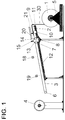
- a conveyor table is shown on the one in a frame 5 rotatably mounted belt storage tape storage roll a continuous belt building belt 30 over a first rotating conveyor belt 2 is conveyed.
- a continuous belt building belt 30 over a first rotating conveyor belt 2 is conveyed.
- belt assembly strips 35 are belt assembly strips 35 with With the help of a knife 21 of a separation device of known type cut off.
- the belt building strips 31 are about first rotating conveyor belt 2 and a second in Circulating conveyor belt 3 downstream promoted a belt building drum of known type and in known way to build the belt drum Belt of a pneumatic vehicle tire put on Conveyor belt 2 is rotating around the deflection rollers 8 and 9 formed, the rotating conveyor rollers 8 and 9 with their parallel to each other and transverse to the conveying direction aligned waves in the table top 11 of the conveyor table are rotatably mounted.
- One of the two shafts of the pulleys 8 and 9 is in a known manner from a controlled drive motor, not shown driven in rotation to promote.
- the table top 11 is Slidably mounted transversely to the conveying direction in the conveyor table. With the help of an actuator 10 of a known type for example one driven by a servomotor Adjustment spindle can be, the table top 11 and thus that revolving funding 2 in its lateral position are controlled controlled.
- the revolving conveyor belt 3 is around deflection rollers 7 and 6 formed all around, the deflection rollers 6 and 7 with their parallel shafts aligned transversely to the conveying direction rotatably mounted in a table top 12 of the conveyor table are.
- One of the two shafts of the deflection rollers 6 and 7, for example, that of the guide roller 6 is in Drive connection to a controlled drive motor.
- Sensor device 15 formed with two sensors 16 and 17, that with the same lateral distance to the middle of the belt revolving conveyor belt 3 arranged above the conveyor level are.
- the sensors 17 and 16 are with a control unit to control the actuator 10 in a known manner in Connection.
- the sensors 16 and 17 are, for example, CCD cameras to detect the lateral web edges 31 and 32 of the Belt building material.
- second rotating conveyor belt 3 are two sensor systems 18 and 19, which are arranged one behind the other, are known Type for detecting the front edge of the belt construction material being conveyed arranged.
- These can, for example, as in Fig. 1 is shown above the conveyor level, e.g. as CCD cameras or be designed as light barriers.
- the second circulating funding from two parallel around the deflection roller rollers 6 and 7 guided conveyor belts 3 '' 'and 3' 'as shown in Fig. 2a is shown in dashed lines.
- the unwound from the belt storage roll 1 and by the first rotating conveyor belt 2, on the upper run in the conveyor belt conveyor belt 30 is an in Belt construction tape manufactured in a known manner, in which parallel steel cords, examples of which are shown in Fig. 2b schematically three are shown, including one acute angle ⁇ between 10 and 35 °, for example 20 °, embedded in rubber to the transverse direction of the conveyor belt are.
- On the upper run of the first rotating conveyor belt 2 extends transversely to the conveying direction including a acute angle ⁇ parallel to the alignment of the steel cords 39 a cutting bar 22, over which parallel to the orientation of the Cutting bar 22 a roller knife 21 of a known type Separating device 20 is designed to be movable for cutting.
- the cutting bar 22 is so over the circumferential Conveyor belt 2 arranged that the belt assembly belt 30 is conveyed from the rotating conveyor belt 2 via the cutting bar 22 pushed away and again from the rotating conveyor belt 2 is taken away.
- the belt building tape 30 is used by the circulating funding 2 and 3 as long as in the direction of funding promoted until the belt assembly tape strip 35 with a Length that corresponds to the desired belt construction strip length Building a belt layer of the belt on the Belt building drum 4 corresponds to the cutting bar 22 happened.
- the funding is stopped and the roller knife 21 is at an angle ⁇ across the cutting bar 22 across the conveyor belt 2 is rolled so that a belt building strip 35 is cut from the belt assembly tape 30.
- the trimmed belt assembly strip 35 is slanted Trailing edge 34 and the belt assembly tape 30 and thus the next belt build-up strip its slanting front edge 33.
- the leading edge 33 and trailing edge 34 are then just like the two side edges 31 and 32 in the area of Tips 36 and 38 strongly curved at the latest after the cut.
- the side edges 31 and 32 of the belt assembly belt 30 and the cut off belt assembly strip 35 also have usually production-related, storage-related and / or by funding up to the first rotating conveyor belt 2 irregularities in the Edge course on.
- FIG. 2a shows the Starting position in which the belt assembly band 30 with its on the cutting bar 22 by the separating device 20 generated front edge 33 rests. The cut was made at stopped conveyor belt 2.
- the belt assembly belt 30 is now as shown by the arrow representation of FIG. 2a, through the rotating conveyor belt 2 in the conveying direction conveyed until the front end portion 37 of the front tip 36 is detected by the side edge sensor 16.
- the conveyor belt 2 is stopped. 2b shows this state.
- the control device, not shown, for controlling the Actuator 10 moves the conveyor table 11 until the position of the side edge measured by the side edge sensor 16 31 of the front tip 37 a predetermined target value for the Side edge position corresponds to the side edge 31.
- This State is shown in Fig. 2c. After that it will Belt assembly belt 30 using the conveyor belt 2 in unchanged lateral position of the conveyor belt 2 as far as Conveyed up to the tip 37 in the Area of influence parallel to the pulley 7 above the Conveyor belt 3 rotatably mounted up and down swiveling support roller 13 arrives.
- This state is in Fig. 2d shown.
- the support roller 13 is lowered, so that it is the frictional force between the upper run of the second Conveyor belt 3 and the tip 17 lying thereon acts supports, enables funding in the direction of funding and a lateral displacement of the tip 17 relative to the upper Trumm of the conveyor belt 3 prevented.
- the conveyor table 11 is then moved using the actuator 10 so far shifted in position until that of the Side edge sensor 16 now sensed portion of the side edge 31, but in the area of the front tip 36
- Direction of conveyance is upstream of the front end area, so far around the end of the tip secured against lateral displacement is pivoted that he of the specified side edge position for the side edge 31 of the front tip 36 corresponds.
- the front tip 36 is now on the side aligned and also in their shape to their target shape deformed.
- the belt assembly band 30 is through the conveyed synchronously driven conveyor belts 2 and 3 as long as until the side edge sensor 17 the side edge 32 of the Belt building tape 30 detected.
- the position of the side edge 31 from the sensor 15 continuously detected and the table 11 proceed accordingly that the Actual position of the side edge 31 in the area of the sensor 15 corresponds to their target position.
- the front tip 36 as far as the conveyor belt 3 was moved that the static friction between conveyor belt 3 and belt assembly belt even without Support rollers is sufficient, the lateral position of the To secure belt assembly belt on the conveyor belt 3, the Support rollers 14 and 16 raised so that they are out of contact come with the belt construction tape. This state is in Fig. 2f shown.
- the alignment mode is for alignment the front tip just a side edge alignment mode, i.e. a mode in which the alignment takes place so that the Side edge 31 of the front tip 36 a predetermined Target position and a predetermined target course takes. From Side edge alignment mode is now on the Center mode switched.
- the belt building tape 30 will continue through the synchronously driven conveyor belts 2 and 3 continuously conveyed, the side edge sensor 16 continuously the position of the between the conveyor belts 2 and 3 detected under the passing side edge 31 and the Side edge sensor 17 continuously between the two revolving conveyor belts 2 and 3 passed under it Side edge 32 detected.
- the determined Deviation from the target position of the center and measured Actuator 10 becomes the actual position of the width center controlled that he moved the table by the amount of deviation so far that the target center position of the Belt construction tape in this longitudinal position of the actual position corresponds.
- the front tip 36 subordinate main part of the belt construction band, both of which Side edges 31, 32 were detected the two side edges still curvilinear after alignment, but symmetrical to the center line of the conveyed on conveyor belt 2 Belt construction tape.
- the belt building tape 30 will continue continuously promoted in operating mode center guidance. According to the desired length of the cut Belt construction strip 35 and the set Conveyor speed of conveyor belts 2 and 3 and The counting speed is continued until the Counting has progressed so far that a number is reached, which indicates that the distance from the front edge 33rd to the cutting line of the roller knife that of the desired length corresponds to the belt assembly strip 35. The funding will stopped.
- the separating knife 21 of the separating device 20 is lowered and on the cutting bar 22 parallel to Alignment of the cutting bar 22 to cut the Belt building strip 35 from the belt building tape 30 rolled along.
- the belt assembly strip 35 is thereby given its rear edge 34, which with the side edge 32 of the Belt building strip 35 including an acute angle the rear tip 38 creates.
- the rear tip 38 At the latest by the The cutting process is the rear tip 38, the rear edge 34 and the side edge 32 in the area of the rear tip 38 often deformed.
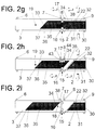
- Fig. 2g shows the remaining belt 30 and the straight cut belt assembly strip 35, but simplified without showing the curvature.
- the Belt assembly strip 35 continues in the conveying direction through the synchronously driven conveyor belts 2 and 3 in operating mode center guidance conveyed until the side edge 31 the gap between conveyor belts 2 and 3 and thus the Detection area of the side edge sensor 16 leaves.
- Two controlled lifting and lowering support rollers 43, 44, the parallel to the pulleys 7 and 8 above the Respective deflection roller 7 and 8 are arranged on facing the side edge 32 of the belt assembly strip 35 Belt construction strip side to reinforce the frictional contact between belt assembly belt 35 and conveyor belt 2 and 3 for Protection against lateral displacement on the conveyor belts lowered in the area of the deflection rollers 7 and 8. That state is shown in Fig. 2h.
- the alignment mode is run by mode center guidance on operating mode side edge guide switched.
- the belt building strip 35 is by the Conveyor belts 2 and 3 continue to be conveyed in the direction of conveyance.
- the sensor 17 continuously detects the position of the Side edge 32 of the rear tip 38.
- the side edge 31 of the front tip 36 or align the side edge 32 of the rear tip 38 so that it forms a straight line parallel to the conveying direction. It is also conceivable, the side edge 31 of the front tip 36 or align the side edge 32 of the rear tip 38 so that a deliberate deviation from a parallel straight line results with the one in the further machining process expected deformation is specifically counteracted. Consequently can, for example, with an expected deformation Side edge 31 of the front tip 36 to the left in Direction of funding through appropriate targeted alignment of these Side edge to the right so that the Belt construction tape on the belt construction drum the desired get straight line alignment.
Landscapes
- Engineering & Computer Science (AREA)
- Textile Engineering (AREA)
- Mechanical Engineering (AREA)
- Tyre Moulding (AREA)
- Registering, Tensioning, Guiding Webs, And Rollers Therefor (AREA)
- Controlling Rewinding, Feeding, Winding, Or Abnormalities Of Webs (AREA)
Abstract
Description
- Fig. 1
- schematische Seitenansicht einer erfindungsgemäßen Förder- und Ausrichteeinrichtung,
- Fig. 2a bis 2i
- erfindungsgemäßer Ablauf der Förderung und Ausrichtung von Gürtelaufbaustreifen in schematischer Draufsicht auf die erfindungsgemäße Förder- und Ausrichteeinrichtung
- 1
- Gürtelbandspeicherrolle
- 2
- umlaufendes Förderband
- 3
- umlaufendes Förderband
- 4
- Gürtelaufbautrommel
- 5
- Gestell
- 6
- Umlenkrolle
- 7
- Umlenkrolle
- 8
- Umlenkrolle
- 9
- Umlenkrolle
- 10
- Stellantrieb
- 11
- Tisch
- 12
- Tisch
- 13
- Auflagerolle
- 14
- Auflagerolle
- 15
- Sensoreinrichtung
- 16
- Seitenkantensensor
- 17
- Seitenkantensensor
- 18
- Vorderkantensensor
- 19
- Vorderkantensensor
- 20
- Trennvorrichtung
- 21
- Messer
- 22
- Schneideleiste
- 30
- Gürtelaufbauband
- 31
- Seitenkante
- 32
- Seitenkante
- 33
- Vorderkante
- 34
- Hinterkante
- 35
- Gürtelaufbaustreifen
- 36
- vordere Spitze
- 37
- Endbereich
- 38
- hintere Spitze
- 39
- Stahlcord
- 43
- Auflagerolle
- 44
- Auflagerolle
Claims (17)
- Verfahren zum Transport eines Gürtelaufbaustreifens für den Aufbau eines Gürtels für einen Fahrzeugluftreifen mit parallelen schräg zur Förderrichtung verlaufend angeordneten in Kautschuk eingebetteten Festigkeitsträgern, insbesondere aus Stahl, zu einer nachgeordneten Weiterverarbeitungseinrichtung und zum Aufbereiten des Gürtelaufbaustreifens zur Weiterverarbeitung in der nachgeordneten Weiterverarbeitungseinrichtung, z.B. einer Gürtelaufbautrommel, wobei der Gürtelaufbaustreifen, der quer zur Förderrichtung zu beiden Seiten hin durch jeweils eine Seitenkante und an seiner vorderen in Förderrichtung und an seiner hinteren in Gegenförderrichtung gerichteten Seite durch eine Vorderkante bzw. durch eine Hinterkante begrenzt ist, die im wesentlichen parallel zu Festigkeisträgern schräg verlaufen, so daß die Vorderkante mit der einen Seitenkante und die Hinterkante mit der anderen Seitenkante jeweils unter Einschluß eines spitzen Winkels von insbesondere 10 bis 35° eine vordere Streifenspitze bzw. eine hintere Streifenspitze bildet, über wenigstens zwei in Förderrichtung hintereinander angeordnete, insbesondere umlaufende, Fördermittel zur Weiterverarbeitungseinrichtung gefördert wird und dabei jeweils ohne seitlichen Anschlag seitlich ausgerichtet wird,wobei zur seitlichen Ausrichtung in einem ersten Schritt die in Förderrichtung vordere Spitze des Gürtelaufbaustreifens hinsichtlich seiner Form und seiner seitlichen Position ausgerichtet wird,wobei in einem weiteren Verfahrensschritt das Hauptteil des Gürtelstreifens, das sich zwischen vorderer Spitze und hinterer Spitze befindet, hinsichtlich seiner seitlichen Position ausgerichtet wird, undwobei in einem dritten Verfahrensschritt die rückwärtige Spitze des Gürtelaufbaustreifens hinsichtlich seiner Formgebung und seiner seitlichen Position ausgerichtet wird.
- Verfahren gemäß den Merkmalen von Anspruch 1, bei dem beiderseits des Gürtelstreifens Sensoren die Position der Gürtelkante erfassen und bei dem aufgrund der ermittelten Positionen der Seitenkanten die Nachregelung erfolgt.
- Verfahren gemäß den Merkmalen von Anspruch 2,wobei zunächst der Sensor, der der vorderen Spitze am nächsten gelegen ist, die Seitenkantenposition der vorderen Spitze ermittelt und aufgrund dieser ermittelten Seitenkantenposition die Spitze so in ihrer Position ausgerichtet und deformiert wird, daß die den Gürtelstreifen begrenzende seitliche Kante im Bereich der vorderen Spitze einer seitlichen Sollkantenausrichtposition und -Kontur entspricht,bei der sodann beide Sensoren den Seitenkantenverlauf der beiden Seitenkanten des Hauptteils ermitteln und die Lage des Hauptteils so ausrichten, daß das Hauptteil an jeder Position in Förderrichtung im Verlauf seiner beiden Seitenkanten seitlich mittensymmetrisch zu einer Achse in Förderrichtung ausgerichtet wird unddaß im Anschluß daran mit Hilfe des zweiten Sensors die Seitenkantenlage der Endspitze ermittelt wird und die Form und die seitliche Position der Endspitze so ausgerichtet wird, daß die seitliche den Gürtelstreifen begrenzende Seite der seitlichen Sollkantenausrichtposition und -Kontur entspricht.
- Verfahren gemäß den Merkmalen von Anspruch 1, 2 oder 3,wobei die vordere Spitze zur Ausrichtung zunächst seitlich mit ihrem vorderen Ende in deren seitliche Sollausrichtposition verschoben wird und insbesondere dort gegen seitliches Verschieben gesichert wird undwobei anschließend bei unveränderter, insbesondere gegen seitliches Verschieben gesicherter, Seitenkantenposition des vorderen Spitzenendes, die Spitze soweit durch seitliches Verschieben von in Förderrichtung nachgeordnetenn Bereichen in der Winkellage ihrer Seitenkantenlage zur Förderrichtung verändert wird, daß die Seitenkante der Spitze den Sollwinkelverlauf einnimmt.
- Verfahren gemäß den Merkmalen der Ansprüche 2, 3 oder 4,wobei der Gürtelaufbaustreifen vom ersten Fördermittel soweit gefördert wird, daß das vordere Ende der vorderen Spitze von einem Sensor zur Erfassung der Seitenkantenlage im Übergangsbereich zum zweiten Fördermittel erfaßt wird,wobei, insbesondere bei unterbrochener Förderung, der Gürtelaufbaustreifen seitlich soweit verschoben wird, bis die vom Sensor ermittelte Seitenkantenposition des vorderen Endes der Sollposition der Seitenkante des vorderen Endes entspricht,wobei danach der Gürtelaufbaustreifen soweit gefördert wird, daß Mitnahmekontakt durch das zweite Fördermittel hergestellt ist, und dann insbesondere die Förderung unterbrochen wird,wobei danach nach Herstellung eines sichernden Haltekontakts zwischen zweitem Fördermittel und vorderem Ende der vorderen Spitze gegen seitliches Verschieben der Gürtelaufbaustreifen durch das erste Fördermittel seitlich soweit verschoben wid, daß die vom Sensor ermittelte Seitenkantenposition der vorderen Spitze der vorgegebenen Sollposition entspricht,bei der danach der Gürtelaufbaustreifen weiter gefördert wird, bis auch die zweite Seitenkante des Gürtelaufbaustreifens von einem Sensor zur Erfassung der Seitenkantenlage im Übergangsbereich zum zweiten Fördermittel erfaßt wird,bei der danach der Gürtelstreifen weitergefördert wird, wobei während der Förderung das erste Fördermittel in Abhängigkeit von der während der Förderung ermittelten seitlichen Ist- Positionen der beiden Seitenkanten so gesteuert seitlich verschoben wird, daß die Seitenkantenverläufe jeweils im wesentlichen symmetrisch zu einer in Förderrichtung verlaufenden Achse sind,und bei der, sobald der Gürtelaufbaustreifen soweit gefördert ist, daß eine Seitenkante in Förderrichtung den Sensorenerfassungsbereich verläßt, die hintere Spitze ausgerichtet wird.
- Verfahren gemäß den Merkmalen von Anspruch 5,wobei zur Sicherung des Haltekontaktes zwischen Gürtelaufbaustreifen und zweitem Fördermittel im Bereich des zweiten Fördermittels eine Auflagerolle (13) auf die Spitze des Gürtelaufbaustreifens gesteuert abgesenkt wird,die vor der Ausrichtung des Hauptteils wieder angehoben wird.
- Verfahren gemäß den Merkmalen von Anspruch 6,wobei zusätzlich zur Sicherung des Haltekontaktes zwischen Gürtelaufbaustreifen und erstem Fördermittel eine Auflagerolle (14) im Bereich des ersten Fördermittels auf die vordere Spitze gesteuert abgesenkt wird,die vor der Ausrichtung des Hauptteils wieder angehoben wird.
- Verfahren gemäß den Merkmalen von Anspruch 5,wobei, nachdem eine Seitenkante in Förderrichtung den Sensorerfassungsbereich verlassen hat, in Abhängigkeit von der durch den Sensor zur Erfassung der Seitenkantenposition der anderen Seitenkante die hintere Spitze durch seitliches Verschieben des ersten Fördermittels gegenüber den am zweiten Fördermittel gegen seitliches Verschieben gehaltenen Gürtelaufbaustreifen soweit seitlich verschoben wird, daß die Seitenkante der hinteren Spitze des Gürtelaufbaustreifens der Sollposition entspricht.
- Verfahren gemäß den Merkmalen von Anspruch 8,bei dem, nach dem das Hauptteil den Spaltbereich zwischen den Fördermitteln verlassen hat, Auflagerollen (43, 44) auf die hintere Spitze zur Sicherung des Haltekontaktes abgesenkt werden, wobei eine Auflagerolle im Bereich des ersten und eine im Bereich des zweiten Fördermittels abgesenkt wird, und bei dem, sobald das hintere Ende den Spalt zwischen den Fördermitteln verlassen hat, die Auflagerollen angehoben werden.
- Verfahren gemäß den Merkmalen von einem oder mehreren der vorangegangenen Ansprüche,wobei die Seitenkantensollposition für die vordere Spitze und/oder für die hintere Spitze von einer Geraden in Förderrichtung um den Betrag der nach der Ausrichtung zu erwartenden späteren Seitenkantenverformung abweicht.
- Verfahren gemäß den Merkmalen von einem oder mehreren der Ansprüche 1 bis 10,wobei der Gürtelaufbaustreifen auf dem ersten Fördermittel von einem Gürtelbandmaterial unter Herstellung der hinteren Kante des Gürtelaufbaustreifen abgeschnitten wird,wobei insbesondere die Länge des abzuschneidenden Gürtelaufbaustreifens mit einer Sollänge durch Sensoren zur Erfassung der Vorderkante des Gürtelaufbaustreifens im Bereich des zweiten, nachgeordneten Fördermittels, erfaßt wird und entsprechend der Erfassung der Gürtelaufbaustreifen nach Erreichen seiner Sollänge abgeschnitten wird.
- Verfahren gemäß den Merkmalen von einem oder mehreren der Ansprüche 1 bis 11,bei dem für einen auf einen geförderten Gürtelaufbaustreifen nachfolgend geförderten Gürtelaufbaustreifen die bei der Einstellung des zuvor geförderten Gürtelaufbaustreifens erzielte Ist-Seitenkantenpositionen als Sollwerte herangezogen werden,bei dem insbesondere für einen ersten Gürtelaufbaustreifen als Sollwerte für die Sollkantenposition der beiden Spitzen Referenzwerte vorgegeben werden.
- Vorrichtung zur Förderung und zum Aufbereiten eines Gürtelaufbaustreifens mit parallelen schräg zur Förderrichtung verlaufend angeordneten in Kautschuk eingebetteten Festigkeitsträgern, insbesondere aus Stahl, zur Weiterverarbeitung in einer nachgeordneten Weiterverarbeitungseinrichtung, insbesondere an einer Gürtelaufbautrommel,wobei zwei hintereinander angeordnete umlaufende Fördermittel ohne seitlichen Anschlag für den Aufbaustreifen zum seitlichen Ausrichten des Aufbaustreifens ausgebildet sind, von denen wenigstens das in Förderrichtung vorgeordnete Fördermittel gesteuert seitlich verschiebbar ausgebildet ist,wobei eine Sensoreinrichtung mit insbesondere wenigstens zwei Sensoren zur Ermittlung der Position der Seitenkanten des Gürtelaufbaustreifens ausgebildet sind,mit Mitteln zum gesteuerten Halten der vorderen Spitze des Gürtelaufbaustreifens im Bereich des zweiten Fordermittels,wobei die Sensoreinrichtung, die Antriebsmittel und die Mittel zum gesteuerten Halten so gekoppelt sind, daß durch seitliche Verschiebung des in Förderrichtung vorgeordneten Fördermittels gegenüber dem nachgeordneten Fördermittel in einem ersten Schritt die in Förderrichtung vordere Spitze des Gürtelaufbaustreifens in seiner Formgebung und Position ausgerichtet werden, daß in einem zweiten Schritt das Hauptteil des Gürtelaufbaustreifens in seiner Formgebung und seiner seitlichen Position mittensymmetrisch ausgerichtet wird, und daß in einem dritten Schritt die hintere in Gegenförderrichtung weisende Spitze hinsichtlich ihrer Formgebung und in ihrer seitlichen Position ausgerichtet wird.
- Vorrichtung gemäß den Merkmalen von Anspruch 13,bei der an dem in Förderrichtung vorgeordneten ersten Fördermittel eine Trennvorrichtung zum Abschneiden der Gürtelaufbaustreifen von einem Gürtelbandmaterial auf dem ersten Fördermittel angeordnet ist.
- Vorrichtung gemäß den Merkmalen von Anspruch 14,bei der im Bereich des zweiten nachgeordneten Fördermittels ein Sensor (18) zur Erfassung der Vorderkante des Bandmaterials zur Längenermittlung des Abstandes zwischen Vorderkante des Bandmaterials und der Trennvorrichtung ausgebildet ist,bei der die Trennvorrichtung so ausgebildet ist, daß sie, sobald der Abstand zwischen Vorderkante des Bandmaterials und der Trennvorrichtung dem der gewünschten Länge des Gürtelaufbaustreifens entspricht, den Gürtelaufbaustreifen abschneidet.
- Vorrichtung gemäß den Merkmalen von Anspruch 13,bei der oberhalb des zweiten in Förderrichtung nachgeordneten Fördermittels eine drehbar gelagerte anhebbare und absenkbare Auflagerolle (13) so gesteuert ausgebildet ist, daß sie zum gesteuerten Halten der vorderen Spitze zum Ausrichten der Spitze so gesteuert abgesenkt wird, daß sie, sobald die vordere Spitze (37) des geförderten Gürtelaufbaustreifenmaterials in ihren Einflußbereich gelangt, auf diese Spitze (37) zur Erhöhung der Reibkraft zwischen Gürtelaufbaustreifen und Fördermittel abgesenkt wird, und daß sie so gesteuert angehoben wird, daß sie während der mittensymmetrischen Ausrichtung des Hauptteils angehoben ist.
- Vorrichtung gemäß den Merkmalen von Anspruch 16,bei der oberhalb des ersten Fördermittels eine drehbar gelagerte, anhebbare und absenkbare Auflagerolle (14) so gesteuert ausgebildet ist, daß sie auf die vordere Spitze zur Erhöhung des Reibkontakts zwischen Fördermittel und Gürtelaufbaustreifen abgesenkt und bei mittensymmetrischer Ausrichtung angehoben ist.
Applications Claiming Priority (2)
| Application Number | Priority Date | Filing Date | Title |
|---|---|---|---|
| DE19641509A DE19641509C2 (de) | 1996-10-09 | 1996-10-09 | Verfahren zum Transport eines Gürtelaufbaustreifens zum Aufbau eines Gürtels für einen Fahrzeugluftreifen |
| DE19641509 | 1996-10-09 |
Publications (2)
| Publication Number | Publication Date |
|---|---|
| EP0835747A2 true EP0835747A2 (de) | 1998-04-15 |
| EP0835747A3 EP0835747A3 (de) | 1999-07-07 |
Family
ID=7808206
Family Applications (1)
| Application Number | Title | Priority Date | Filing Date |
|---|---|---|---|
| EP97117308A Withdrawn EP0835747A3 (de) | 1996-10-09 | 1997-10-07 | Verfahren zum Transport eines Gürtelaufbaustreifens zum Aufbau eines Gürtels für einen Fahrzeugluftreifen |
Country Status (4)
| Country | Link |
|---|---|
| US (2) | US6547906B1 (de) |
| EP (1) | EP0835747A3 (de) |
| JP (1) | JPH10156966A (de) |
| DE (1) | DE19641509C2 (de) |
Cited By (6)
| Publication number | Priority date | Publication date | Assignee | Title |
|---|---|---|---|---|
| DE102006018642A1 (de) * | 2006-04-21 | 2007-10-25 | Texmag Gmbh Vertriebsgesellschaft Gmbh | Vorrichtung zum Erfassen von Parametern einer Kante eines Materialstückes und zum Regeln des Versatzes desselben |
| EP2697050A1 (de) * | 2011-04-12 | 2014-02-19 | Harburg-Freudenberger Maschinenbau GmbH | Verfahren und vorrichtung zur ausrichtung eines gürtelstreifens |
| CN104553011A (zh) * | 2013-10-15 | 2015-04-29 | 卡尔欧根菲舍尔有限公司 | 用于切割帘线带的纵断机 |
| WO2016103078A1 (en) * | 2014-12-24 | 2016-06-30 | Pirelli Tyre S.P.A. | Tyre building plant and method for supplying an elongated element to a forming drum in a tyre building plant |
| CN104553012B (zh) * | 2013-10-15 | 2017-08-29 | 卡尔欧根菲舍尔有限公司 | 用于切割帘线的纵断机 |
| EP3495130A1 (de) | 2017-12-11 | 2019-06-12 | Continental Reifen Deutschland GmbH | Verfahren zum aufwickeln eines zur herstellung eines gürtels eines fahrzeugluftreifens geeigneten gürtelaufbaustreifens auf eine gürtelaufbautrommel und eine entsprechende vorrichtung |
Families Citing this family (24)
| Publication number | Priority date | Publication date | Assignee | Title |
|---|---|---|---|---|
| US6841017B2 (en) * | 2000-09-14 | 2005-01-11 | Bridgestone Corporation | Re-treading method and apparatus |
| DE10127746B4 (de) * | 2001-06-08 | 2006-03-30 | A-Z Formen- Und Maschinenbau Gmbh | Ablängvorrichtung für Laufstreifen |
| NL1024009C2 (nl) * | 2003-07-28 | 2005-02-07 | Vmi Epe Holland | Loopvlakapplicatieinrichting. |
| RU2359829C2 (ru) * | 2004-03-18 | 2009-06-27 | ВМИ ЭПЕ Холланд Б.В. | Режущее устройство, устройство и способ (варианты) для расположения брекерного слоя |
| US7441318B2 (en) * | 2005-02-09 | 2008-10-28 | The Goodyear Tire & Rubber Co | Method for detecting exposed metal cords in an elastomeric strip |
| DE102005041565A1 (de) * | 2005-09-01 | 2007-03-08 | Continental Aktiengesellschaft | Vorrichtung zum Aufspulen eines streifenförmigen Kautschukmaterials |
| DE102006017882B4 (de) * | 2006-04-13 | 2010-08-05 | Texmag Gmbh Vertriebsgesellschaft | Vorrichtung und Verfahren zum Aufbau eines Reifens |
| DE102006033987A1 (de) * | 2006-07-22 | 2008-01-24 | Continental Aktiengesellschaft | Zubringereinrichtung |
| DE102008021042B4 (de) | 2008-04-26 | 2023-09-28 | Continental Reifen Deutschland Gmbh | Verfahren zum Aufwickeln eines Materialstreifens auf eine Reifenaufbautrommel mit einem Servicer |
| DE102008039738B4 (de) * | 2008-08-26 | 2011-01-05 | Continental Reifen Deutschland Gmbh | Verfahren für eine Positionskorrektur einer Spitze eines Reifenaufbauteiles beim Übergang von einem ersten zu einem zweiten Förderband |
| JP2011143688A (ja) * | 2010-01-18 | 2011-07-28 | Bridgestone Corp | タイヤ製造装置 |
| MX379010B (es) | 2013-03-28 | 2025-03-10 | Pirelli | Proceso y aparato para la fabricacion de llantas para ruedas de vehiculo. |
| NL2011764C2 (en) * | 2013-11-08 | 2015-05-11 | Vmi Holland Bv | Method for centering a tire component. |
| NL2018959B1 (en) * | 2017-05-22 | 2018-12-04 | Vmi Holland Bv | Method and assembly for applying a tire component to a drum |
| KR102017620B1 (ko) | 2017-12-07 | 2019-09-03 | 금호타이어 주식회사 | 벨트 컨베이어의 벨트 자석 각도 자동 조절 장치 |
| DE102017222372A1 (de) | 2017-12-11 | 2019-06-13 | Continental Reifen Deutschland Gmbh | Vorrichtung und Verfahren zum Aufwickeln eines zur Herstellung eines Gürtels eines Fahrzeugluftreifens geeigneten Gürtelaufbaustreifens auf eine Gürtelaufbautrommel |
| JP6993873B2 (ja) * | 2017-12-28 | 2022-01-14 | Toyo Tire株式会社 | タイヤ用ベルトの製造方法及び製造装置 |
| JP6993875B2 (ja) | 2017-12-28 | 2022-01-14 | Toyo Tire株式会社 | タイヤ構成部材の製造方法及びタイヤ構成部材の製造装置 |
| JP6970613B2 (ja) | 2017-12-28 | 2021-11-24 | Toyo Tire株式会社 | タイヤ構成部材の製造方法及びタイヤ構成部材の製造装置 |
| NL2020539B1 (en) * | 2018-03-06 | 2019-09-13 | Vmi Holland Bv | Apparatus and method for correcting misalignment of a strip |
| JP6566084B1 (ja) * | 2018-05-17 | 2019-08-28 | 横浜ゴム株式会社 | ゴムシート部材の供給装置および方法 |
| JP7214942B2 (ja) * | 2018-12-26 | 2023-01-31 | Toyo Tire株式会社 | タイヤ構成部材の製造装置及びタイヤ構成部材の製造方法 |
| JP7249625B2 (ja) * | 2019-01-24 | 2023-03-31 | Acs株式会社 | カッティング装置 |
| NL2024050B1 (en) * | 2019-10-18 | 2021-06-22 | Vmi Holland Bv | Method and apparatus for correcting a feeding distance of a strip for cutting |
Family Cites Families (15)
| Publication number | Priority date | Publication date | Assignee | Title |
|---|---|---|---|---|
| US3490674A (en) * | 1968-03-25 | 1970-01-20 | Rockford Servo Corp | Web alignment apparatus |
| US4359675A (en) * | 1980-05-07 | 1982-11-16 | The Firestone Tire & Rubber Company | Electrical control system and method for a tire building machine server |
| JPS5890938A (ja) * | 1981-11-25 | 1983-05-30 | Bridgestone Corp | 帯状材料の両端部接合方法及びその装置 |
| DE3223048C2 (de) * | 1982-06-19 | 1984-07-05 | Canon K.K., Tokio/Tokyo | Verfahren zum Ausrichten eines durch Walzenpaare laufenden Papierblattes sowie Vorrichtung zur Durchführung des Verfahrens und Anwendung desselben |
| US4769104A (en) * | 1986-11-11 | 1988-09-06 | Bridgestone Corporation | Apparatus for sticking a tire component member |
| US5194107A (en) * | 1987-09-03 | 1993-03-16 | Bridgestone Corporation | Belt-like member attaching method and apparatus |
| JPH01110134A (ja) | 1987-10-23 | 1989-04-26 | Mitsubishi Heavy Ind Ltd | メタルコードストリツプの貼付装置 |
| JPH085142B2 (ja) * | 1988-12-21 | 1996-01-24 | 三菱重工業株式会社 | ブレーカの自動供給装置 |
| US5092946A (en) * | 1989-02-22 | 1992-03-03 | Bridgestone Corporation | Method for sticking a belt-like member and apparatus therefore |
| JP2741057B2 (ja) * | 1989-03-27 | 1998-04-15 | 横浜ゴム株式会社 | スチールベルト切断部形状の矯正方法及びその装置 |
| JPH03166149A (ja) * | 1989-11-24 | 1991-07-18 | Bridgestone Corp | 帯状部材の供給方法および供給装置 |
| JPH03109827U (de) * | 1990-02-26 | 1991-11-12 | ||
| US5206720A (en) * | 1991-12-16 | 1993-04-27 | Bridgestone Corporation | Apparatus and technique for monitoring component position during tire building |
| NL9301717A (nl) * | 1993-10-06 | 1995-05-01 | Vmi Epe Holland | Werkwijze voor het aanpassen van een zijde van een strook flexibel materiaal aan een referentiezijde en gordelstrooktoevoerinrichting voor het toevoeren van een gordelstrook op een ronddraaiende opbouwtrommel. |
| DE4407964A1 (de) * | 1994-03-10 | 1995-09-14 | Continental Ag | Verfahren und Vorrichtung zum automatischen Auflegen und Spleißen von Materialbahnen auf eine Reifenaufbautrommel |
-
1996
- 1996-10-09 DE DE19641509A patent/DE19641509C2/de not_active Expired - Fee Related
-
1997
- 1997-10-07 EP EP97117308A patent/EP0835747A3/de not_active Withdrawn
- 1997-10-08 US US08/947,149 patent/US6547906B1/en not_active Expired - Lifetime
- 1997-10-09 JP JP9277152A patent/JPH10156966A/ja active Pending
-
2002
- 2002-11-15 US US10/294,732 patent/US6994140B2/en not_active Expired - Fee Related
Cited By (13)
| Publication number | Priority date | Publication date | Assignee | Title |
|---|---|---|---|---|
| DE102006018642A1 (de) * | 2006-04-21 | 2007-10-25 | Texmag Gmbh Vertriebsgesellschaft Gmbh | Vorrichtung zum Erfassen von Parametern einer Kante eines Materialstückes und zum Regeln des Versatzes desselben |
| EP2697050A1 (de) * | 2011-04-12 | 2014-02-19 | Harburg-Freudenberger Maschinenbau GmbH | Verfahren und vorrichtung zur ausrichtung eines gürtelstreifens |
| CN104553011B (zh) * | 2013-10-15 | 2017-09-22 | 卡尔欧根菲舍尔有限公司 | 用于切割帘线带的纵断机 |
| CN104553011A (zh) * | 2013-10-15 | 2015-04-29 | 卡尔欧根菲舍尔有限公司 | 用于切割帘线带的纵断机 |
| CN104553012B (zh) * | 2013-10-15 | 2017-08-29 | 卡尔欧根菲舍尔有限公司 | 用于切割帘线的纵断机 |
| WO2016103078A1 (en) * | 2014-12-24 | 2016-06-30 | Pirelli Tyre S.P.A. | Tyre building plant and method for supplying an elongated element to a forming drum in a tyre building plant |
| CN107107508A (zh) * | 2014-12-24 | 2017-08-29 | 倍耐力轮胎股份公司 | 轮胎建造设备及将细长元件供应到轮胎建造设备的成型鼓中的方法 |
| RU2690340C2 (ru) * | 2014-12-24 | 2019-05-31 | Пирелли Тайр С.П.А. | Сборочная установка для шин и способ подачи удлиненного элемента на формирующий барабан в шиносборочной установке |
| CN107107508B (zh) * | 2014-12-24 | 2019-07-30 | 倍耐力轮胎股份公司 | 轮胎建造设备及将细长元件供应到轮胎建造设备的成型鼓中的方法 |
| US10500802B2 (en) | 2014-12-24 | 2019-12-10 | Pirelli Tyre S.P.A. | Tyre building plant and method for supplying an elongated element to a forming drum in a tyre building plant |
| US10875269B2 (en) | 2014-12-24 | 2020-12-29 | Pirelli Tyre S.P.A. | Tyre building plant and method for supplying an elongated element to a forming drum in a tyre building plant |
| EP3495130A1 (de) | 2017-12-11 | 2019-06-12 | Continental Reifen Deutschland GmbH | Verfahren zum aufwickeln eines zur herstellung eines gürtels eines fahrzeugluftreifens geeigneten gürtelaufbaustreifens auf eine gürtelaufbautrommel und eine entsprechende vorrichtung |
| DE102017222371A1 (de) | 2017-12-11 | 2019-06-13 | Continental Reifen Deutschland Gmbh | Verfahren zum Aufwickeln eines zur Herstellung eines Gürtels eines Fahrzeugluftreifens geeigneten Gürtelaufbaustreifens auf eine Gürtelaufbautrommel und eine entsprechende Vorrichtung |
Also Published As
| Publication number | Publication date |
|---|---|
| DE19641509A1 (de) | 1998-04-16 |
| DE19641509C2 (de) | 1999-06-24 |
| US20030066610A1 (en) | 2003-04-10 |
| US6994140B2 (en) | 2006-02-07 |
| JPH10156966A (ja) | 1998-06-16 |
| EP0835747A3 (de) | 1999-07-07 |
| US6547906B1 (en) | 2003-04-15 |
Similar Documents
| Publication | Publication Date | Title |
|---|---|---|
| DE19641509C2 (de) | Verfahren zum Transport eines Gürtelaufbaustreifens zum Aufbau eines Gürtels für einen Fahrzeugluftreifen | |
| EP2046566B1 (de) | Zubringereinrichtung | |
| DE69412204T3 (de) | Verfahren zur Anpassung des Randes eines flexiblen Streifens an einer Referenzseite und Vorrichtung zum Zuführen eines Gürtelstreifens zu einer drehbaren Reifenaufbautrommel | |
| EP2674279B2 (de) | Verfahren zum Rollbiegen eines Profils, Profil, Verfahren zur Herstellung gebogener Profilwerkstücke, gebogenes Profilwerkstück, Vorrichtung zum Rollbiegen eines Profils sowie Extrusions- und Rollbiegelinie | |
| DE69618750T2 (de) | Vorrichtung und Verfahren zum Auflegen einer Reifenlauffläche | |
| EP0671255A1 (de) | Verfahren und Vorrichtung zum automatischen Auflegen und Spleissen von Materialbahnen auf eine Reifenaufbautrommel | |
| DE4404907C2 (de) | Spleißautomat | |
| EP3110603B1 (de) | Herstellung gekrümmter preformen | |
| DE602005004581T2 (de) | Verfahren und Vorrichtung zur Herstellung eines Gegenstandes durch Wickeln eines Gummistreifens auf einen Tragkörper | |
| EP0771643B1 (de) | Verfahren zur Förderung eines Bandes aus plastischem Material und Fördertisch zur kontinuierlichen Förderung von bandförmigem plastischem Material | |
| WO2018162237A1 (de) | Vorrichtung und verfahren zum zertrennen eines bands in eine vielzahl von einzelnen bandstücken | |
| DE3900251C2 (de) | ||
| DE102014116270B3 (de) | Anlage und Verfahren zur kontinuierlichen Herstellung gekrümmter Preformen | |
| DE202019102104U1 (de) | Fördereinrichtung zum Fördern geschnittener, dünner und klebriger Bandabschnitte, insbesondere Stahl- oder Textilcordbandabschnitte | |
| EP3495131B1 (de) | Vorrichtung und verfahren zum aufwickeln eines zur herstellung eines gürtels eines fahrzeugluftreifens geeigneten gürtelaufbaustreifens auf eine gürtelaufbautrommel | |
| EP2716170B2 (de) | Vorrichtung zum Transport von band- oder streifenförmigem Material | |
| EP3142952B1 (de) | Vorrichtung und verfahren zum einstellen der position einer packstoffbahn zu einer referenz in einer verpackungsmaschine | |
| EP2808281B1 (de) | Spleißeinrichtung zum Spleißen von Cordmaterial | |
| EP3495130B1 (de) | Verfahren zum aufwickeln eines zur herstellung eines gürtels eines fahrzeugluftreifens geeigneten gürtelaufbaustreifens auf eine gürtelaufbautrommel und eine entsprechende vorrichtung | |
| EP2561973A1 (de) | Vorrichtung und Verfahren zum Herstellen von Tubenkörpern | |
| EP1899145B1 (de) | Verfahren und vorrichtung einsetzbar im automatisiert ablaufenden aufbau eines fahrzeugluftreifens | |
| DE3744107C2 (de) | ||
| DE3137858C1 (de) | Verfahren und Vorrichtung zur Regelung der Bandkantenanbiegung bei der Herstellung von Schraubennahtrohren | |
| DE102007001151A1 (de) | Vorrichtung zum Schneiden und Spleissen von Bandabschnitten eines klebrigen Kordbandes | |
| DE102008039738B4 (de) | Verfahren für eine Positionskorrektur einer Spitze eines Reifenaufbauteiles beim Übergang von einem ersten zu einem zweiten Förderband |
Legal Events
| Date | Code | Title | Description |
|---|---|---|---|
| PUAI | Public reference made under article 153(3) epc to a published international application that has entered the european phase |
Free format text: ORIGINAL CODE: 0009012 |
|
| AK | Designated contracting states |
Kind code of ref document: A2 Designated state(s): DE FR GB IT |
|
| PUAL | Search report despatched |
Free format text: ORIGINAL CODE: 0009013 |
|
| AK | Designated contracting states |
Kind code of ref document: A3 Designated state(s): AT BE CH DE DK ES FI FR GB GR IE IT LI LU MC NL PT SE |
|
| 17P | Request for examination filed |
Effective date: 20000107 |
|
| AKX | Designation fees paid |
Free format text: DE FR GB IT |
|
| 17Q | First examination report despatched |
Effective date: 20010418 |
|
| STAA | Information on the status of an ep patent application or granted ep patent |
Free format text: STATUS: THE APPLICATION IS DEEMED TO BE WITHDRAWN |
|
| 18D | Application deemed to be withdrawn |
Effective date: 20010829 |