EP0835787A1 - Coussin gonflable pour un système de retenue des occupants d'un véhicule - Google Patents
Coussin gonflable pour un système de retenue des occupants d'un véhicule Download PDFInfo
- Publication number
- EP0835787A1 EP0835787A1 EP97117326A EP97117326A EP0835787A1 EP 0835787 A1 EP0835787 A1 EP 0835787A1 EP 97117326 A EP97117326 A EP 97117326A EP 97117326 A EP97117326 A EP 97117326A EP 0835787 A1 EP0835787 A1 EP 0835787A1
- Authority
- EP
- European Patent Office
- Prior art keywords
- gas bag
- film
- airbag according
- outflow opening
- bag wall
- Prior art date
- Legal status (The legal status is an assumption and is not a legal conclusion. Google has not performed a legal analysis and makes no representation as to the accuracy of the status listed.)
- Withdrawn
Links
- 239000000463 material Substances 0.000 claims abstract description 13
- 239000011888 foil Substances 0.000 claims abstract description 9
- 229910052751 metal Inorganic materials 0.000 claims abstract description 3
- 239000002184 metal Substances 0.000 claims abstract description 3
- 230000002787 reinforcement Effects 0.000 claims description 11
- 230000003014 reinforcing effect Effects 0.000 claims description 8
- 229910052782 aluminium Inorganic materials 0.000 claims description 4
- XAGFODPZIPBFFR-UHFFFAOYSA-N aluminium Chemical compound [Al] XAGFODPZIPBFFR-UHFFFAOYSA-N 0.000 claims description 4
- 239000002985 plastic film Substances 0.000 claims description 2
- 229920006255 plastic film Polymers 0.000 claims description 2
- 238000004026 adhesive bonding Methods 0.000 claims 1
- 238000007599 discharging Methods 0.000 claims 1
- 238000009958 sewing Methods 0.000 claims 1
- 238000003466 welding Methods 0.000 claims 1
- 239000004033 plastic Substances 0.000 abstract description 3
- 229920003023 plastic Polymers 0.000 abstract description 3
- 239000005030 aluminium foil Substances 0.000 abstract 1
- 238000000926 separation method Methods 0.000 abstract 1
- 239000004744 fabric Substances 0.000 description 7
- 238000004519 manufacturing process Methods 0.000 description 4
- 230000006378 damage Effects 0.000 description 3
- 238000000034 method Methods 0.000 description 3
- 239000011248 coating agent Substances 0.000 description 2
- 238000000576 coating method Methods 0.000 description 2
- 230000006835 compression Effects 0.000 description 2
- 238000007906 compression Methods 0.000 description 2
- 238000002347 injection Methods 0.000 description 1
- 239000007924 injection Substances 0.000 description 1
Images

Classifications
-
- B—PERFORMING OPERATIONS; TRANSPORTING
- B60—VEHICLES IN GENERAL
- B60R—VEHICLES, VEHICLE FITTINGS, OR VEHICLE PARTS, NOT OTHERWISE PROVIDED FOR
- B60R21/00—Arrangements or fittings on vehicles for protecting or preventing injuries to occupants or pedestrians in case of accidents or other traffic risks
- B60R21/02—Occupant safety arrangements or fittings, e.g. crash pads
- B60R21/16—Inflatable occupant restraints or confinements designed to inflate upon impact or impending impact, e.g. air bags
- B60R21/23—Inflatable members
- B60R21/239—Inflatable members characterised by their venting means
Definitions
- the invention relates to an airbag for a vehicle occupant restraint system, with a gas bag wall, the at least one Outflow opening, which by a covering, at the Airbag wall attached piece of material up to a predetermined Airbag pressure is closed and when the Internal pressure is released by tearing the piece of material.
- a gas bag of the generic type is already known from EP 0 495 410 A1 known.
- the discharge openings provided serve the purpose of Limit the airbag pressure, and in particular to adjust the airbag the impact of the vehicle occupant at the end of the vehicle compression path to soften. They show through to the defined opening Pieces of material covered outflow openings on tear lines that e.g. perforations or slits closed by tear seams are formed.
- the pieces of material tear from a predetermined Inner airbag pressure and expose the outflow openings. This is particularly the case when tearing seams are provided
- Problem that the defined gas bag pressure, which is used to tear the seam leads, can vary from gas bag to gas bag. It therefore requires higher Manufacturing accuracies to keep these fluctuations as narrow as possible Keep limits.
- US 4 805 930 shows an airbag with an outflow opening, which is closed by a plastic-coated piece of fabric. At high pressure, the individual threads of the piece of fabric move in this way strongly to each other that the plastic layer in numerous places tears and many small outflow openings are formed. The openings are however relatively small, so that a rapid drop in pressure in the gas bag can hardly be reached. Due to non-excluded Manufacturing tolerances regarding the fabric and the coating the airbag pressure from which the opening is exposed fluctuates from Airbag to airbag considerably.
- the invention creates an easy-to-manufacture gas bag which is the predetermined internal pressure from which the outflow opening is exposed, can be kept within narrow, very precisely predeterminable limits.
- a gas bag of the type mentioned at the outset according to the invention achieved in that the piece of material is a film.
- a film be made so that it is due to its exact producible thickness at a desired pressure acting on it tears.
- the inside of the airbag to expose the outflow opening should be manufactured.
- the film can be a metal or plastic film that is on the Airbag wall sewn on the inside or outside, glued or is welded on.
- Tear lines in the film ensure a defined Opening process and prevent the film from tearing so that it is loose Individual parts are created that fly in the direction of the vehicle occupant could.
- the film can a surface section lying in the region of the outflow opening reduced thickness compared to the remaining surface section exhibit.
- the outflow opening surrounding reinforcement ring is in a preferred embodiment on the gas bag sewn, glued or welded, the outflow opening surrounding reinforcement ring provided.
- the slide is between the Reinforcement ring and the gas bag wall arranged and on both Parts attached.
- To evenly apply the force to the Unfolding the gas bag into the film has a reinforcement ring Inside diameter that is larger than the diameter of the inside Airbag wall provided outflow opening.
- the position of the film must be towards the outflow opening and Reinforcement ring, if one is provided, aligned exactly be so that the film runs all the way around the Airbag wall is attached.
- a positioning opening in the film facilitates the alignment of the film relative to the outflow opening. Since the diameter of the positioning opening can be very small they have no significant impact on the course of the airbag pressure.
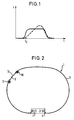
- Fig. 1 is the course of the pressure inside a gas bag shown during the unfolding process. With broken lines the pressure curve shown in a conventional gas bag, the Outflow opening is always exposed. Because the outflow opening too When the unfolding process is already open, the pressure in the Airbag slowly and steadily on again after reaching a maximum fall off.
- the gas bag internal pressure is limited to a lower level, and the gas bag becomes soft at the end of the vehicle compression path and can absorb energy.
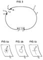
- the airbag 1 shown in FIG. 2 includes an airbag wall 3 an injection opening 5 into which a gas generator 7 projects.
- the Airbag wall 3 has several outflow openings, of which only an outflow opening, which is designated by 9, is shown.
- the Outflow opening 9 is from one on the inside of the gas bag wall 3 adjacent piece of material covered in the form of an aluminum foil 11 and locked.
- the film 11 is provided with a circumferential seam 13 attached to the gas bag wall 3.
- the film 11 is made of a reinforcing ring 16 Surround airbag fabric material whose inner diameter is larger than that Diameter of the outflow opening 9 provided in the gas bag wall 3 is.
- the reinforcement ring 16 prevents the film 11 from being torn out the seam 13, since the film 11 between the reinforcing ring 16 and the Airbag wall 3 is held.
- the introduction of force into the film 11 increased internal pressure follows larger areas and not only in Area of seam stitches.
- the reinforcement ring 16 is in the in Figures 2 and 3 shown embodiment with a circumferential seam 13 attached to the gas bag wall 3 together with the film 11, wherein however, several seams can also be provided, the fastening the reinforcing ring 16 or the film 11 to each other or to the Airbag wall 3 serve.
- the reinforcing ring 16 prevents tearing, in particular then the film 11 in the area of the seam 13 if its inside diameter unequal, in particular larger than the diameter of the in Airbag wall 3 provided outflow opening 9.
- the Reinforcement ring 16 is made of gas bag fabric material.
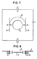
- the thickness of the aluminum foil 11 is based on the geometry of the Outflow opening 9 matched that they only after reaching the predetermined airbag pressure breaks, as shown in Fig. 3.
- the Seams 13 hold the individual parts of the film 11 on the gas bag 1 so that they are not thrown in the direction of the vehicle occupant can.
- the impressions 15, which form tear lines, can be different Take shapes, e.g. a star shape (see. Fig. 4a), a part circle or spoon-like shape (see Fig. 4b) or a cross shape (see Fig. 4c). Common to all of these forms, however, is that none are loose Individual parts can arise, but that all after tearing the The resulting individual parts 11 remain attached to the gas bag 1.
- the film can optionally be heat-resistant Coating should be provided.
- the film 11 is open the gas bag wall 3 glued or welded on the inside.
- the film 11 has a circular surface section 18 in the region of the outflow opening 9, which has a smaller thickness than that has remaining surface section. This is to ensure be that the film 11 not at the edge, but always in the area of their Middle tears open first after being at a higher internal pressure extends outwards through the outflow opening 9 (FIG. 5b).
- a positioning opening 19 in the film 11 serves to secure the position Hold the film 11 when attaching it to the gas bag wall 3.
- a Pneumatically extendable mandrel passes through through the positioning opening 19, whereupon the film 11 in the area sewn, glued or its outer edge to the gas bag wall 3 is welded.
- the positioning opening 19 has only one Diameter of about 3 mm on what the course of the gas bag pressure not significantly influenced until the film 11 tears.
- one or more positioning openings 19 in the area of Providing outflow opening 9 is also possible, as in FIG. 6 shown, one or preferably two positioning openings 19 in To provide the area of the outer edge of the film 11, the corresponding Positioning openings in the gas bag wall 3 and in one Reinforcement ring 16 are aligned. Through all positioning openings extends through during the manufacture of the gas bag 1 Appropriate extendable and retractable mandrel that the parts positioned to each other.
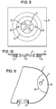
- FIGS 9 and 10 are both the retaining ring 16 and the gas bag wall 3 are not annular, but cut out into segments of a circle, with the adjacent circular segment-shaped openings to the outlet opening 9 add.
- holding parts 31 bridge made of fabric material, the outflow opening 9. These holding parts 31 cross in the middle and connect opposite areas of the gas bag wall 3 with each other. As a result, the shape of the outflow opening 9 stabilized when gas is released. Further, as in the embodiment 7, no tensile force over the gas bag wall 3 in the Slide 11 initiated. Cutting out the gas bag wall 3 to reach it The four circular segment-shaped openings are made by laser.
- Fig. 11 is an outside area 33 of the gas bag, which has the outflow opening 9, sewn.
- tear seam 35 connects opposite regions of the gas bag wall 3.
- the area 33 is not inflated, so that no gas can escape through the outflow opening 9.
- a very high airbag pressure which leads to the destruction of the tear seam 35.
- gas then flows into area 33 and outflow opening 9 into the open.
- a plurality of tear seams 35 can also be provided, and the Tear seam 35 can also have several and not just two layers of the gas bag wall 3 connect with each other. So when the gas flows out over the Outflow openings 9 the gas bag does not collapse asymmetrically and the occupant slides along it are preferably several, symmetrical Outflow openings arranged as seen from the vehicle occupant 9 provided on the sides of the gas bag.
Landscapes
- Engineering & Computer Science (AREA)
- Mechanical Engineering (AREA)
- Air Bags (AREA)
Applications Claiming Priority (4)
| Application Number | Priority Date | Filing Date | Title |
|---|---|---|---|
| DE29617586U | 1996-10-09 | ||
| DE29617586U DE29617586U1 (de) | 1996-10-09 | 1996-10-09 | Gassack für ein Fahrzeuginsassen-Rückhaltesystem |
| DE29621077U | 1996-12-04 | ||
| DE29621077U DE29621077U1 (de) | 1996-10-09 | 1996-12-04 | Gassack für ein Fahrzeuginsassen-Rückhaltesystem |
Publications (1)
| Publication Number | Publication Date |
|---|---|
| EP0835787A1 true EP0835787A1 (fr) | 1998-04-15 |
Family
ID=26059507
Family Applications (1)
| Application Number | Title | Priority Date | Filing Date |
|---|---|---|---|
| EP97117326A Withdrawn EP0835787A1 (fr) | 1996-10-09 | 1997-10-07 | Coussin gonflable pour un système de retenue des occupants d'un véhicule |
Country Status (2)
| Country | Link |
|---|---|
| EP (1) | EP0835787A1 (fr) |
| JP (1) | JPH10119679A (fr) |
Cited By (10)
| Publication number | Priority date | Publication date | Assignee | Title |
|---|---|---|---|---|
| WO2002014115A1 (fr) * | 2000-08-03 | 2002-02-21 | Dalphi Metal España, S.A. | Airbag pourvu d'un bouchon d'obturation de l'orifice de decharge de gaz d'epaisseur variable |
| EP1288080A3 (fr) * | 2001-08-24 | 2003-09-24 | Automotive Safety Components International GmbH & Co. KG | Coussin gonflable adapté à un système de sécurité à sac gonflable |
| DE102004011578A1 (de) * | 2004-03-10 | 2005-09-29 | Hübner GmbH | Falten- oder Wellenbalg eines Übergangs zwischen zwei Fahrzeugteilen |
| DE202004019445U1 (de) * | 2004-12-16 | 2006-04-20 | Trw Automotive Safety Systems Gmbh & Co. Kg | Gassackmodul mit Abströmöffnung |
| EP1700753A1 (fr) * | 2005-03-07 | 2006-09-13 | Dalphi Metal Espana, S.A. | Airbag a evacuation double controlé de gaz d'gonflement |
| WO2008039109A1 (fr) * | 2006-09-25 | 2008-04-03 | Autoliv Development Ab | Airbag (coussin gonflable) |
| EP2008881A1 (fr) * | 2007-06-29 | 2008-12-31 | Dalphi Metal Espana, S.A. | Couvercle de protection de l'orifice de ventilation du sac d'un module de sac gonflable |
| US7641224B2 (en) | 2005-07-18 | 2010-01-05 | Takata-Petri Ag | Vehicle occupant restraint system including an airbag |
| EP2439113A1 (fr) * | 2010-10-06 | 2012-04-11 | Autoliv Development AB | Airbag gonflable pour choc piéton |
| US12552341B1 (en) * | 2025-03-21 | 2026-02-17 | Ford Global Technologies, Llc | Airbag with vents having different venting characteristics |
Families Citing this family (2)
| Publication number | Priority date | Publication date | Assignee | Title |
|---|---|---|---|---|
| JP4360525B2 (ja) | 2003-07-02 | 2009-11-11 | 芦森工業株式会社 | エアバッグ装置 |
| JP2015039959A (ja) * | 2013-08-22 | 2015-03-02 | ダイハツ工業株式会社 | サイドエアバッグ装置 |
Citations (9)
| Publication number | Priority date | Publication date | Assignee | Title |
|---|---|---|---|---|
| DE1962890A1 (de) * | 1968-12-18 | 1970-07-09 | Eaton Yale & Towne | Sicherheitsgeraet |
| US3527475A (en) * | 1969-03-07 | 1970-09-08 | Eaton Yale & Towne | Vehicle safety system |
| DE8800530U1 (de) * | 1988-01-19 | 1988-02-25 | Dr.Ing.H.C. F. Porsche Ag, 7000 Stuttgart | Aufprallschutzvorrichtung für den Insassen eines Fahrzeuges |
| EP0495410A1 (fr) * | 1991-01-17 | 1992-07-22 | TRW Occupant Restraint Systems GmbH | Coussin d'air gonflable pour un système de retenue dans des véhicules |
| EP0495409A1 (fr) * | 1991-01-17 | 1992-07-22 | TRW Occupant Restraint Systems GmbH | Coussin d'air gonflable pour un système de retenue dans des véhicules |
| DE4412829A1 (de) * | 1993-04-17 | 1994-10-20 | Phoenix Ag | Aufprallschutzvorrichtung, insbesondere für Insassen von Fahrzeugen |
| JPH07329693A (ja) * | 1994-06-10 | 1995-12-19 | Takata Kk | エアバッグの内圧調節装置 |
| JPH07329695A (ja) * | 1994-06-10 | 1995-12-19 | Takata Kk | エアバッグの内圧調節装置 |
| GB2306409A (en) * | 1995-10-23 | 1997-05-07 | Autoliv Dev | Airbag vent valves opened by a command signal |
-
1997
- 1997-10-07 EP EP97117326A patent/EP0835787A1/fr not_active Withdrawn
- 1997-10-09 JP JP27748097A patent/JPH10119679A/ja active Pending
Patent Citations (9)
| Publication number | Priority date | Publication date | Assignee | Title |
|---|---|---|---|---|
| DE1962890A1 (de) * | 1968-12-18 | 1970-07-09 | Eaton Yale & Towne | Sicherheitsgeraet |
| US3527475A (en) * | 1969-03-07 | 1970-09-08 | Eaton Yale & Towne | Vehicle safety system |
| DE8800530U1 (de) * | 1988-01-19 | 1988-02-25 | Dr.Ing.H.C. F. Porsche Ag, 7000 Stuttgart | Aufprallschutzvorrichtung für den Insassen eines Fahrzeuges |
| EP0495410A1 (fr) * | 1991-01-17 | 1992-07-22 | TRW Occupant Restraint Systems GmbH | Coussin d'air gonflable pour un système de retenue dans des véhicules |
| EP0495409A1 (fr) * | 1991-01-17 | 1992-07-22 | TRW Occupant Restraint Systems GmbH | Coussin d'air gonflable pour un système de retenue dans des véhicules |
| DE4412829A1 (de) * | 1993-04-17 | 1994-10-20 | Phoenix Ag | Aufprallschutzvorrichtung, insbesondere für Insassen von Fahrzeugen |
| JPH07329693A (ja) * | 1994-06-10 | 1995-12-19 | Takata Kk | エアバッグの内圧調節装置 |
| JPH07329695A (ja) * | 1994-06-10 | 1995-12-19 | Takata Kk | エアバッグの内圧調節装置 |
| GB2306409A (en) * | 1995-10-23 | 1997-05-07 | Autoliv Dev | Airbag vent valves opened by a command signal |
Non-Patent Citations (1)
| Title |
|---|
| PATENT ABSTRACTS OF JAPAN vol. 096, no. 004 30 April 1996 (1996-04-30) * |
Cited By (12)
| Publication number | Priority date | Publication date | Assignee | Title |
|---|---|---|---|---|
| WO2002014115A1 (fr) * | 2000-08-03 | 2002-02-21 | Dalphi Metal España, S.A. | Airbag pourvu d'un bouchon d'obturation de l'orifice de decharge de gaz d'epaisseur variable |
| ES2166726A1 (es) * | 2000-08-03 | 2002-04-16 | Dalphi Metal Espana Sa | Airbag con parche de obturacion en orificio de descarga de gas mejorado. |
| EP1288080A3 (fr) * | 2001-08-24 | 2003-09-24 | Automotive Safety Components International GmbH & Co. KG | Coussin gonflable adapté à un système de sécurité à sac gonflable |
| DE102004011578A1 (de) * | 2004-03-10 | 2005-09-29 | Hübner GmbH | Falten- oder Wellenbalg eines Übergangs zwischen zwei Fahrzeugteilen |
| DE202004019445U1 (de) * | 2004-12-16 | 2006-04-20 | Trw Automotive Safety Systems Gmbh & Co. Kg | Gassackmodul mit Abströmöffnung |
| EP1671857A1 (fr) * | 2004-12-16 | 2006-06-21 | TRW Automotive Safety Systems GmbH | Module de sac à gaz avec trou d'évent |
| EP1700753A1 (fr) * | 2005-03-07 | 2006-09-13 | Dalphi Metal Espana, S.A. | Airbag a evacuation double controlé de gaz d'gonflement |
| US7641224B2 (en) | 2005-07-18 | 2010-01-05 | Takata-Petri Ag | Vehicle occupant restraint system including an airbag |
| WO2008039109A1 (fr) * | 2006-09-25 | 2008-04-03 | Autoliv Development Ab | Airbag (coussin gonflable) |
| EP2008881A1 (fr) * | 2007-06-29 | 2008-12-31 | Dalphi Metal Espana, S.A. | Couvercle de protection de l'orifice de ventilation du sac d'un module de sac gonflable |
| EP2439113A1 (fr) * | 2010-10-06 | 2012-04-11 | Autoliv Development AB | Airbag gonflable pour choc piéton |
| US12552341B1 (en) * | 2025-03-21 | 2026-02-17 | Ford Global Technologies, Llc | Airbag with vents having different venting characteristics |
Also Published As
| Publication number | Publication date |
|---|---|
| JPH10119679A (ja) | 1998-05-12 |
Similar Documents
| Publication | Publication Date | Title |
|---|---|---|
| EP0974498B1 (fr) | Système de retenue à sac de sécurité gonflable | |
| DE19847854C2 (de) | Zweikammerluftsack | |
| DE4234988C2 (de) | Gassack-Struktur | |
| EP0810126B1 (fr) | Sac de sécurité gonflable | |
| EP0945312A2 (fr) | Dispositif de coussin de sécurité pour véhicule | |
| DE102007056137B4 (de) | Gassack mit einem Einfüllstutzen und Gassackanordnung mit einem Gassack und einem Gasgenerator | |
| DE20022020U1 (de) | Gassackmodul | |
| DE1962890A1 (de) | Sicherheitsgeraet | |
| DE202007006023U1 (de) | Gassackanordnung für ein Fahrzeuginsassen-Rückhaltesystem | |
| EP1172263A2 (fr) | Module avec une paroi de coussin gonflable présentant un renfoncement | |
| DE60215712T2 (de) | Airbag mit Abströmöffnung und Verfahren zu dessen Herstellung | |
| DE29621077U1 (de) | Gassack für ein Fahrzeuginsassen-Rückhaltesystem | |
| DE20010562U1 (de) | Verbesserungen an oder bezüglich einer Sicherheitsanordnung | |
| DE69728200T2 (de) | Doppelte Luftsackstruktur mit einem inneren Luftsack aus Elastomer und Verfahren zu ihrer Herstellung | |
| DE19517315A1 (de) | Gassack | |
| EP1467898B1 (fr) | Module de coussin gonflable de securite destine a des vehicules | |
| EP1354768A2 (fr) | Module de sac gonflable et procédé de fixation un coussin gonflable sur un dispositif de support d'un sac gonflable | |
| EP1781506B1 (fr) | Sac gonflable pour prot ger un occupant dans un v hicule | |
| DE102018106288B4 (de) | Gassackmodul, Lenkrad und Kraftfahrzeug | |
| DE19903361A1 (de) | Verfahren zur Herstellung eines Luftsackes und Luftsack | |
| EP2387518B1 (fr) | Ensemble sac gonflable pour un système de retenue des occupants d'un véhicule | |
| WO2011073445A1 (fr) | Coussin à gaz pour un système de protection de personnes d'un véhicule et procédé pour sa fabrication | |
| DE19532768A1 (de) | Gassack-Rückhaltemodul | |
| DE202018006264U1 (de) | Gassackanordnung für ein Fahrzeuginsassen-Rückhaltesystem eines Kraftfahrzeuges | |
| WO2023030806A1 (fr) | Volant doté d'un airbag |
Legal Events
| Date | Code | Title | Description |
|---|---|---|---|
| PUAI | Public reference made under article 153(3) epc to a published international application that has entered the european phase |
Free format text: ORIGINAL CODE: 0009012 |
|
| AK | Designated contracting states |
Kind code of ref document: A1 Designated state(s): DE FR GB IT |
|
| AX | Request for extension of the european patent |
Free format text: AL;LT;LV;RO;SI |
|
| RAP1 | Party data changed (applicant data changed or rights of an application transferred) |
Owner name: TRW OCCUPANT RESTRAINT SYSTEMS GMBH & CO. KG |
|
| GBC | Gb: translation of claims filed (gb section 78(7)/1977) | ||
| EL | Fr: translation of claims filed | ||
| 17P | Request for examination filed |
Effective date: 19980811 |
|
| AKX | Designation fees paid |
Free format text: DE FR GB IT |
|
| RBV | Designated contracting states (corrected) |
Designated state(s): DE FR GB IT |
|
| 17Q | First examination report despatched |
Effective date: 19991029 |
|
| STAA | Information on the status of an ep patent application or granted ep patent |
Free format text: STATUS: THE APPLICATION IS DEEMED TO BE WITHDRAWN |
|
| 18D | Application deemed to be withdrawn |
Effective date: 20000309 |