EP0835803B1 - Lüftungssystem zur Klimatisierung eines Grossraumpassagierflugzeuges - Google Patents
Lüftungssystem zur Klimatisierung eines Grossraumpassagierflugzeuges Download PDFInfo
- Publication number
- EP0835803B1 EP0835803B1 EP97117219A EP97117219A EP0835803B1 EP 0835803 B1 EP0835803 B1 EP 0835803B1 EP 97117219 A EP97117219 A EP 97117219A EP 97117219 A EP97117219 A EP 97117219A EP 0835803 B1 EP0835803 B1 EP 0835803B1
- Authority
- EP
- European Patent Office
- Prior art keywords
- air
- area
- recycling
- unit
- cabin
- Prior art date
- Legal status (The legal status is an assumption and is not a legal conclusion. Google has not performed a legal analysis and makes no representation as to the accuracy of the status listed.)
- Expired - Lifetime
Links
- 238000004378 air conditioning Methods 0.000 title claims description 11
- 238000009423 ventilation Methods 0.000 title claims description 6
- 238000004064 recycling Methods 0.000 claims description 29
- 230000001143 conditioned effect Effects 0.000 claims description 4
- 230000001105 regulatory effect Effects 0.000 claims description 3
- 238000000034 method Methods 0.000 claims description 2
- 238000005253 cladding Methods 0.000 description 6
- 230000002411 adverse Effects 0.000 description 2
- 239000000446 fuel Substances 0.000 description 2
- 238000013517 stratification Methods 0.000 description 2
- 244000052616 bacterial pathogen Species 0.000 description 1
- 239000000356 contaminant Substances 0.000 description 1
- 238000001816 cooling Methods 0.000 description 1
- 230000001627 detrimental effect Effects 0.000 description 1
- 235000019645 odor Nutrition 0.000 description 1
- 239000002245 particle Substances 0.000 description 1
- 231100000614 poison Toxicity 0.000 description 1
- 239000003440 toxic substance Substances 0.000 description 1
Images
Classifications
-
- B—PERFORMING OPERATIONS; TRANSPORTING
- B64—AIRCRAFT; AVIATION; COSMONAUTICS
- B64D—EQUIPMENT FOR FITTING IN OR TO AIRCRAFT; FLIGHT SUITS; PARACHUTES; ARRANGEMENT OR MOUNTING OF POWER PLANTS OR PROPULSION TRANSMISSIONS IN AIRCRAFT
- B64D13/00—Arrangements or adaptations of air-treatment apparatus for aircraft crew or passengers, or freight space
- B64D13/06—Arrangements or adaptations of air-treatment apparatus for aircraft crew or passengers, or freight space the air being conditioned
- B64D13/08—Arrangements or adaptations of air-treatment apparatus for aircraft crew or passengers, or freight space the air being conditioned the air being heated or cooled
-
- B—PERFORMING OPERATIONS; TRANSPORTING
- B64—AIRCRAFT; AVIATION; COSMONAUTICS
- B64C—AEROPLANES; HELICOPTERS
- B64C1/00—Fuselages; Constructional features common to fuselages, wings, stabilising surfaces or the like
- B64C2001/0018—Fuselages; Constructional features common to fuselages, wings, stabilising surfaces or the like comprising two decks adapted for carrying passengers only
- B64C2001/0027—Fuselages; Constructional features common to fuselages, wings, stabilising surfaces or the like comprising two decks adapted for carrying passengers only arranged one above the other
-
- B—PERFORMING OPERATIONS; TRANSPORTING
- B64—AIRCRAFT; AVIATION; COSMONAUTICS
- B64D—EQUIPMENT FOR FITTING IN OR TO AIRCRAFT; FLIGHT SUITS; PARACHUTES; ARRANGEMENT OR MOUNTING OF POWER PLANTS OR PROPULSION TRANSMISSIONS IN AIRCRAFT
- B64D13/00—Arrangements or adaptations of air-treatment apparatus for aircraft crew or passengers, or freight space
- B64D13/06—Arrangements or adaptations of air-treatment apparatus for aircraft crew or passengers, or freight space the air being conditioned
- B64D2013/0603—Environmental Control Systems
- B64D2013/0651—Environmental Control Systems comprising filters, e.g. dust filters
-
- B—PERFORMING OPERATIONS; TRANSPORTING
- B64—AIRCRAFT; AVIATION; COSMONAUTICS
- B64D—EQUIPMENT FOR FITTING IN OR TO AIRCRAFT; FLIGHT SUITS; PARACHUTES; ARRANGEMENT OR MOUNTING OF POWER PLANTS OR PROPULSION TRANSMISSIONS IN AIRCRAFT
- B64D13/00—Arrangements or adaptations of air-treatment apparatus for aircraft crew or passengers, or freight space
- B64D13/06—Arrangements or adaptations of air-treatment apparatus for aircraft crew or passengers, or freight space the air being conditioned
- B64D2013/0603—Environmental Control Systems
- B64D2013/0688—Environmental Control Systems with means for recirculating cabin air
-
- Y—GENERAL TAGGING OF NEW TECHNOLOGICAL DEVELOPMENTS; GENERAL TAGGING OF CROSS-SECTIONAL TECHNOLOGIES SPANNING OVER SEVERAL SECTIONS OF THE IPC; TECHNICAL SUBJECTS COVERED BY FORMER USPC CROSS-REFERENCE ART COLLECTIONS [XRACs] AND DIGESTS
- Y02—TECHNOLOGIES OR APPLICATIONS FOR MITIGATION OR ADAPTATION AGAINST CLIMATE CHANGE
- Y02T—CLIMATE CHANGE MITIGATION TECHNOLOGIES RELATED TO TRANSPORTATION
- Y02T50/00—Aeronautics or air transport
- Y02T50/50—On board measures aiming to increase energy efficiency
Definitions
- the invention relates to a ventilation system for air conditioning a large passenger aircraft according to the preamble of claim 1.
- Passenger aircraft consists of the fact that in the upper ceiling area of a passenger cabin temperature-controlled mixed air is blown in.
- the used mixed air flows through the cabin area and leaves the cabin on the one hand close to or immediately in exhaust air cross-sections embedded in and below the cabin floor.
- This part of the used cabin air becomes the (the longitudinally distributed) in the fuselage arranged outflow or exhaust air valve (s) fed, then the exhaust air (pressure-controlled) to the outside environment to the outside of the aircraft.
- aircraft fuselages are equipped with a multi-deck configuration are, several aircraft cabins arranged one above the other, over large stairwells or stairwells are connected to each other.
- the flow behavior the air through the upper passenger cabin of a passenger plane made up of several decks would adversely change if you look at these aircraft cabins the known state of the art - air-conditioned.
- Since the resistance as a result of Stairwell connection between the individual decks (multi-deck configuration) at Air flow is many times smaller than the resistance of the exhaust air cross-sections of the aircraft, the blown recycled mixed air becomes the upper Most of the (pressure) cabin escapes via the stairwells. After that would use large longitudinal currents in this cabin, although disadvantageous Temperature stratification and passenger comfort problems are generated. These problems would increase if the fresh air supply was set variably becomes.
- the solution is that the amount of air extracted from the upper deck with a blower is not correspond to the airflow that is supplied to the upper deck. Thus will inevitably set an overpressure or underpressure in the upper deck, which does not lead to one desired air exchange between the upper and lower deck would result, provided the two decks would be connected by a staircase or a staircase. Furthermore, the solution provides that the exhaust air from the upper deck with the exhaust air from the main deck mixed in a common local mixing chamber and then branched.
- the relevant mixing chamber outlet would be disadvantageously large pipe cross sections (inner diameter) that take up more space and also the weight and fuel consumption of a multi-deck passenger aircraft would adversely affect.
- the invention is based on the object of a generic ventilation system for air conditioning a large passenger aircraft, in which several passenger decks are connected via stairwells or stairways in such a way that with him an air exchange with balanced pressure conditions between the passenger decks excluded via the stairwell or stairway connections becomes.
- a uniform flow through all cabin cross sections (over the Cabin length) without cross-sectional longitudinal flow (along the Fuselage longitudinal axis) can be achieved, with temperature stratification problems that a would have a detrimental impact on passenger comfort are.
- Laying unfavorable cross sections of the airflow connections Influence on the total weight and fuel consumption of the material-intensive Having a large passenger aircraft should be avoided.
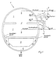
- Fig. 1 shows an overview of the ventilation system for air conditioning the large passenger aircraft
- the aircraft pressure fuselage 1 is divided into several decks.
- the fuselage cross section includes an upper and a main deck area 2, 3 for passengers, a lower deck area 4 for accompanying cargo and cargo, and an exhaust air area 8 located below it.
- the upper and main deck areas 2, 3 and the exhaust air area 8 functionally represent a pressurized cabin.
- a duct-like pressure chamber connection 5 which accommodates a stairwell or a stairway that can be used for flight passengers, combines the upper and main deck areas 2, 3 with one another. Both ceiling areas include a passenger area, which is air-conditioned together.
- the air recycling of the passenger area to be air-conditioned is operated with two recycling units 6, 7.
- the recycling units 6, 7 consist consistently of a filter unit 61, 71, which is made up of a plurality of dedicated filters connected in series to remove particles, odors and germs and other contaminants (toxic substances, etc.) from the used exhaust air from the passenger cabin, and a blower unit 62, 72 for the air intake of the cabin exhaust air, which are connected in series in relation to the air flow.
- the fan unit 62, 72 in question consists of at least one fan which operates in a speed-controlled manner. With the characteristic speed control of the blower unit 62, 72, the vented (extracted) and correlatively the ventilating (blown) volume flow of the air can be precisely regulated, which will be discussed later. It is added that the filter unit 61, 71 is connected to the inlet and the blower unit 62, 72 is connected to the outlet of the recycling unit (6; 7).
- the solution provides that the upper deck area 2 with a first and a second Recycling unit 6, 7 is connected. Both recycling units 6, 7 take on the input side a partial amount (a share of the total amount) of the cabin air used Upper deck area (2) as recirculation air.
- the first recycling unit is 6 with an upper ceiling outlet (not shown), for example above a Hatrack box and near a ceiling panel in the side panel of the Cabin can lie connected.
- the second recycling unit 7 is connected to an air outlet (not shown), which is close to the floor area of the upper deck area 2 in the side wall cladding the cabin. Furthermore, the exit of the first recycling unit 6 with a first functional interface 9 and the exit of the second recycling unit 7 connected to a second functional interface 10.
- a separate mixing unit (not shown) is integrated into these separate functional interfaces 9, 10.
- the interfaces 9, 10 are each connected to a fresh air line, via which externally obtained tempered fresh air is supplied. Since the two recycling units 6, 7 prepare (filtered) recirculation air on the output side, this recirculation air is mixed with fresh air after reaching the relevant interface 9, 10 by means of the mixing unit.
- the ventilation system is supplemented such that the first interface 9 is connected to the upper deck area 2 and the second interface 10 to the main deck area 3. This means that the interface-related mixed air is supplied separately to the climate area (upper deck and main deck area) via separate connections.
- the outgoing mixed air-carrying line from the first interface 9 is connected to a ceiling inlet (not shown) which is let in approximately in the middle of the ceiling cladding of the upper deck 2.
- the outgoing mixed air-carrying line from the second interface 10 is connected to a ceiling inlet (not shown), which is embedded, for example, above a hat rack box and near a ceiling cladding in the side wall cladding of the main deck area 3.
- the used exhaust air of the main deck area 3 is at least one exhaust air duct 81, 82 vented, which opens into an exhaust air area 8 of the aircraft. there opens into the main deck area 3 on the left and right sides and close to it Side wall cladding an exhaust air duct 81, 82, the exhaust air area 8 with the main deck area 3 Connects airflow related.
- the cross section of the exhaust duct concerned 81, 82 leads past the underfloor area 4. It is through the side panel limited below the main deck area 3.
- temperature-controlled mixed air is blown into the upper deck area 2 for air conditioning.
- the recirculation proportion of the mixed air is taken directly from this area in that the blower unit 62 of the first recycling unit 6 draws in the used (and previously cleaned by the filter unit 61) cabin exhaust air and then admits the interface-related supply air [(upper deck) fresh air].
- the blower unit 62 of the first recycling unit 6 draws in the used (and previously cleaned by the filter unit 61) cabin exhaust air and then admits the interface-related supply air [(upper deck) fresh air].
- the speed-controlled blower 72 the recycling unit 7.
- This cabin exhaust air taken from the upper deck area 2 is admixed to the interface-related (main deck) fresh air as processed recirculation air (deck transfer air) via the filter unit 71 of the second recycling unit 7, which cleans this exhaust air after suction (before).
- This temperature-controlled (main deck) mixed air flows through the main deck area 3 and leaves it via the exhaust air cross sections.
- This (main deck) exhaust air is transported outside the aircraft pressure fuselage 1 through the exhaust air area 8 (the exhaust air pressure chamber) below the main deck area 3, from where it leaves the aircraft pressure fuselage 1 via a (not shown regulated) outflow valve.
- the air exchange via the channel-like pressure chamber connection 5 (staircase or staircase) is avoided and a uniform flow through all ventilated passenger cabin cross sections without longitudinal cabin flow is achieved.
- a uniform cross-sectional flow through the cabin length can be set. 10/10/96
- the desired cabin airflow is due to the arrangement of the cabin air outlets determined in a cabin cross-section.
- the upper deck area 2 extracted air used as recirculation air for the main deck area 3.
- the solution demonstrates that the flow through the exhaust air cross-sections pressure build-up in the main deck area 3 is even over the channel-like Pressure chamber connection 5 (stairwell, cladding slots) on the whole Passenger area (upper and main deck area 2, 3) balances and balanced Pressure chamber internal pressures guaranteed. Regardless of the size of the fresh air component supplied or the blown (mixed) air volumes, the two areas have the same Pressure chamber internal pressure on; are the internal pressures of the two pressure chambers always balanced against each other.
Landscapes
- Health & Medical Sciences (AREA)
- General Health & Medical Sciences (AREA)
- Pulmonology (AREA)
- Engineering & Computer Science (AREA)
- Aviation & Aerospace Engineering (AREA)
- Air-Conditioning For Vehicles (AREA)
- Central Air Conditioning (AREA)
Description
Die Fig. 1 zeigt eine Übersicht des Lüftungssystem zur Klimatisierung des Großraumpassagierflugzeuges, dessen Flugzeug-Druckrumpf 1 in mehrere Decks unterteilt ist. Dabei schließt der Rumpfquerschnitt einen Ober- und einen Hauptdeckbereich 2, 3 für Passagiere, einen Unterdeckbereich 4 für begleitendes Fracht- und Ladegut und einen diesem darunter gelegenen Abluftbereich 8 ein. Der Ober- und Hauptdeckbereich 2, 3 und der Abluftbereich 8 stellen funktionell eine Druckkabine dar. Eine kanalartige Druckkammerverbindung 5, die ein für Flugpassagiere benutzbares Treppenhaus oder einen Treppenaufgang aufnimmt, vereint den Ober- und Hauptdeckbereich 2, 3 miteinander. Beide Deckenbereiche schließen einen Passagierbereich ein, der gemeinsam klimatisiert wird. Das Luftrecycling des zu klimatisierenden Passagierbereiches wird mit zwei Recyclingeinheiten 6, 7 betrieben.
Die Recyclingeinheiten 6, 7 bestehen einheitlich aus einer Filtereinheit 61, 71, welche sich aus mehreren in Reihe geschalteten zweckbestimmten Filtern zur Beseitigung von Partikeln, Gerüchen und Keime sonstigen Verschmutzungen (toxische Stoffe ect.) aus der verbrauchten Abluft der Passagierkabine aufbaut, und einer Gebläseeinheit 62, 72 zur Luftansaugung der Kabinenabluft zusammensetzt, die luftstrombezogen in Reihe verbunden sind. Die betreffende Gebläseeinheit 62, 72 besteht aus wenigstens einem Lüfter, der drehzahlgeregelt arbeitet. Mit der charakteristischen Drehzahlregelung der Gebläseeinheit 62, 72 läßt sich der entlüftete (abgesaugte) und korrelativ der belüftende (eingeblasene) Volumenstrom der Luft genauestens regulieren, worauf später eingegangen wird. Es wird ergänzt, daß die Filtereinheit 61, 71 auf den Eingang und die Gebläseeinheit 62, 72 auf den Ausgang der Recyclingeinheit (6; 7) geschalten ist.
Das Lüftungssytem wird derart ergänzt, wonach die erste Schnittstelle 9 mit dem Oberdeckbereich 2 und die zweite Schnittstelle 10 mit dem Hauptdeckbereich 3 verbunden ist. Damit wird dem Klimabereich (Oberdeck- und Hauptdeckbereich) bereichsweise getrennt die schnittstellenbezogene Mischluft über separaten Verbindungen zugeführt. Die der ersten Schnittstelle 9 abgehende mischluftführende Leitung ist mit einem (nicht gezeigten) Deckeneinlaß, der etwa in Mitte der Deckenverkleidung des Oberdecks 2 eingelassen ist, verbunden. Die der zweiten Schnittstelle 10 abgehende mischluftführende Leitung ist mit einem (nicht gezeigten) Deckeneinlaß, der beispielsweise oberhalb eines Hatrackkastens und nahe einer Deckenverkleidung in der Seitenwandverkleidung des Hauptdeckbereiches 3 eingelassen ist, verbunden.
Es wird erwähnt, daß (allgemein) alle in einen Luftstrom einbezogenen Recyclingeinheiten 6, 7 und Verbindungen mittels Luftstromverbindungsleitungen oder -kanäle realisiert sind.
Durch die Anwendung der Lösung wird der Luftaustausch über die kanalartige Druckkammerverbindung 5 (Treppenhaus bzw. Aufgang) vermieden sowie eine gleichmäßige Durchströmung aller belüfteten Passagierkabinenquerschnitte ohne Kabinenlängsströmung erreicht. Infolge dessen läßt sich eine gleichmäßige Kabinenquerschnittsdurchströmung über die Kabinenlänge einstellen. 10.10.96
Claims (1)
- Lüftungs- und Klimatisierungssystem eines Großraumpassagierflugzeuges, bei dem ein FlugzeugOruckrumpf in mehrere Decks unterteilt ist, dessen Rumpfquerschnitt wenigstens einen Ober- und einen Hauptdeckbereich (2, 3) für Passagiere, einen Unterdeckbereich (4) für begleitendes Fracht- und Ladegut und einen diesem darunter gelegenen Abluftbereich (8) einschließt, wobei der Ober- und Hauptdeckbereich (2, 3), die miteinander durch wenigstens eine kanalartige Druckkammerverbindung (5) verbunden sind und einen gemeinsamen Klimabereich einschließen, und der Abluftbereich (8) funktionell eine Druckkabine darstellen, bei dem der Oberdeckbereich (2) mit dem Eingang einer ersten und einer zweiten Recyclingeinheit (6, 7), die beide eingangsseitig einen Teil der verbrauchten Kabinenluft des Oberdeckbereiches (2) als Rezirkulationsluft aufnehmen, verbunden ist, und die erste Recyclingeinheit (6) ausgangsseitig mit einer ersten separaten funktionellen Schnittstelle (9) sowie die zweite Recyclingeinheit (7) ausgangsseitig mit einer zweiten separaten funktionellen Schnittstelle (10) verbunden ist, denen schnittstellenbezogen jeweils eine Mischeinneit integriert ist, wobei die Mischeinheit der ersten funktionellen Schnittstelle (9) eingangsseitig mit dem Ausgang der ersten Recyclingeinheit (6) und die Mischeinheit der zweiten funktionellen Schnittstelle (10) eingangsseitig mit dem Ausgang der zweiten Recyclingeinheit (7) verbunden ist, und wobei der Ausgang der Mischeinheit der ersten funktionellen Schnittstelle (9) über eine mischluftführende Leitung und der Eingang der zweiten Recyclingeinheit (7) über eine rezirkulationsluftführende Leitung mit dem Oberdeckbereich (2) verbunden ist, und wobei außerdem die betreffende Mischeinheit der ersten und zweiten funktionellen Schnittstelle (9, 10) eingangsseitig an eine Frischluftleitung, über die eine extern bezogene Frischluft zugeführt wird, angeschlossen ist, bei dem weiterhin die betreffende Mischeinheit der ersten und zweiten funktionellen Schnittstelle (9, 10) einen Teil der ausgangsseitig der betreffenden Recyclingeinheit (6, 7) bereitgestellten aufbereiteten Rezirkulationsluft, die als verbrauchte Kabinenluft des Oberdeckbereiches (2) über die rezirkulationsluftführende Leitung eingangsseitig der betreffenden Recyclingeinheit (6, 7) als Rezirkulationsluft aufgenommen und von dieser aufbereitet wird, mit der bezogenen Frischluft vermischt, die nach geschehenem Mischvorgang ausgangsseitig der beiden funktionellen Schnittstellen (9, 10) als Mischluft bereitgestellt wird, wobei das Luftrecycling des Klimabereiches mit den beiden Recydingeinheiten (6, 7), denen eine Gebläseeinheit (62, 72) integriert ist, umgesetzt wird, bei dem in den Hauptdeckbereich (3) wenigstens ein Abluftkanal (81, 82) mündet, mit dem der Abluftbereich (8) luftstrombezogen verbunden ist, durch den ein Teil der im Klimabereich verbrauchten Abluft als Kabinenluft den Abluftbereich (8) erreicht, die über wenigstens ein im Flugzeug-Druckrumpf installiertes Ausströmventil das Flugzeug verlässt, bei dem die in einen Luftstrom einbezogenen Recyclingeinheiten (6, 7) und Verbindungen mittels Luftstromverbindungsleitungen oder - kanäle realisiert sind.
dadurch gekennzeichnet, dass der schnittstellenbezogenen Mischeinheit der zweiten funktionellen Schnittstelle (10) ausgangsseitig eine mischluftführende Leitung angeschlossen ist, die dem Hauptdeckbereich (3) verbunden ist, dass die Gebläseeinheiten (62, 72) der beiden Recyclingeinheiten (6, 7) mit wenigstens einem drehzahlgeregelten Lüfter ausgestattet sind, mit dem sich der Volumenstrom der aus dem Oberdeckbereich (2) abgesaugten Kabinenluft und der in den Klimabereich eingeblasenen Mischluft genauestens regeln lässt, wobei wenigstens mit dem drehzahlgeregelten Gebläse (72) der zweiten Recyclingeinheit (7) genau die dem Oberdeckbereich (2) von der ersten funktionellen Schnittstelle (9) zugeführte Frischluft abgesaugt wird, um eine ausgeglichene Volumenstrombilanz des Oberdeckbereichs (2) umzusetzen und einen Druckaufbau oder Druckabbau im Oberdeckbereich (2) zu verhindern, wodurch über die Druckkammerverbindung (5) ein Luftaustausch vermieden wird.
Applications Claiming Priority (2)
| Application Number | Priority Date | Filing Date | Title |
|---|---|---|---|
| DE19642203 | 1996-10-12 | ||
| DE19642203A DE19642203C1 (de) | 1996-10-12 | 1996-10-12 | Lüftungssystem zur Klimatisierung eines Großraumpassagierflugzeuges |
Publications (3)
| Publication Number | Publication Date |
|---|---|
| EP0835803A2 EP0835803A2 (de) | 1998-04-15 |
| EP0835803A3 EP0835803A3 (de) | 2001-05-16 |
| EP0835803B1 true EP0835803B1 (de) | 2004-09-22 |
Family
ID=7808620
Family Applications (1)
| Application Number | Title | Priority Date | Filing Date |
|---|---|---|---|
| EP97117219A Expired - Lifetime EP0835803B1 (de) | 1996-10-12 | 1997-10-04 | Lüftungssystem zur Klimatisierung eines Grossraumpassagierflugzeuges |
Country Status (5)
| Country | Link |
|---|---|
| US (1) | US5890957A (de) |
| EP (1) | EP0835803B1 (de) |
| JP (1) | JP3088982B2 (de) |
| DE (2) | DE19642203C1 (de) |
| ES (1) | ES2229305T3 (de) |
Cited By (1)
| Publication number | Priority date | Publication date | Assignee | Title |
|---|---|---|---|---|
| DE102005061189B4 (de) * | 2005-12-21 | 2015-01-08 | Airbus Operations Gmbh | Flugzeugrumpf mit Ober- und Unterdeck |
Families Citing this family (24)
| Publication number | Priority date | Publication date | Assignee | Title |
|---|---|---|---|---|
| DE59904160D1 (de) * | 1998-03-26 | 2003-03-06 | Fraunhofer Ges Forschung | Verfahren und vorrichtung zur klimatisierung von fahrzeugen und insbesondere von flugzeugen |
| DE19940165B4 (de) * | 1999-06-17 | 2006-06-01 | Airbus Deutschland Gmbh | Anordnung zur Klimatisierung von Unterflurbereichen eines Pasagierflugzeuges |
| DE19927606C2 (de) | 1999-06-17 | 2002-02-28 | Eads Airbus Gmbh | Anordnung zur Klimatisierung von Unterflurbereichen eines Passagierflugzeuges |
| DE50005307D1 (de) | 1999-08-25 | 2004-03-25 | Airbus Gmbh | Anordnung zur Klimatisierung von Unterflurbereichen eines Passagierflugzeuges |
| DE19943071B4 (de) * | 1999-09-09 | 2004-09-16 | Airbus Deutschland Gmbh | Verfahren und Anordnung zur Klimatisierung von einander angrenzenden Zonen eines druckbeaufschlagten Bereiches in einem Flugzeug |
| DE10011238B4 (de) * | 2000-03-08 | 2007-10-25 | Airbus Deutschland Gmbh | Hochleistungsklimaanlage mit redundanter und gestufter Rezirkulationsluftzumischung für ein Verkehrsflugzeug |
| US20060131161A1 (en) * | 2001-05-07 | 2006-06-22 | Towler Gavin P | Air sanitation with hydrogen peroxide |
| US6684660B1 (en) | 2002-08-08 | 2004-02-03 | Hamilton Sundstrand | Pneumatic cabin super charger |
| US6755036B1 (en) * | 2002-12-06 | 2004-06-29 | Spex International | Confined space conditioning system |
| GB2409718A (en) * | 2003-06-06 | 2005-07-06 | David Whittingham | Aircraft air disinfection system |
| WO2005063573A1 (en) | 2003-12-30 | 2005-07-14 | Airbus Deutschland Gmbh | Method and device for the air-conditioning of a freight compartment or a cabin of an aircraft |
| DE102006014572B4 (de) * | 2006-03-29 | 2008-08-28 | Airbus Deutschland Gmbh | Vorrichtung und Verfahren zur Luftverteilung in einem Frachtflugzeug |
| US7789346B2 (en) * | 2006-09-29 | 2010-09-07 | The Boeing Company | Cabin air supply apparatus with filtered air |
| DE102007045755A1 (de) * | 2007-09-25 | 2009-04-09 | Nord-Micro Ag & Co. Ohg | Auslassventil für ein Flugzeug |
| ES2528920T3 (es) * | 2008-02-25 | 2015-02-13 | Hatchtech Group B.V. | Uso de un separador ciclónico y cámara climática para incubar huevos y/o mantener aves de corral |
| DE102008035122B4 (de) * | 2008-07-28 | 2011-01-13 | Airbus Operations Gmbh | System und Verfahren zur Förderung von Rezirkulationsluft aus einer Flugzeugkabine |
| DE102008053668B4 (de) * | 2008-10-29 | 2010-11-25 | Airbus Deutschland Gmbh | System und Verfahren zur Klimatisierung einer Flugzeugkabine mit verbesserter Kühlleistung |
| WO2011124390A1 (en) * | 2010-04-09 | 2011-10-13 | Airbus Operations Gmbh | Mixer assembly for an aircraft air conditioning system |
| CN101973402A (zh) * | 2010-09-26 | 2011-02-16 | 北京航空航天大学 | 一种适用于大型运输机的新型可变式送风系统 |
| US9511869B2 (en) | 2012-12-21 | 2016-12-06 | Hamilton Sunstrand Corporation | Mixer and air pack for use in aircraft air supply system |
| US9862494B2 (en) | 2014-09-25 | 2018-01-09 | Hamilton Sundstrand Corporation | Flight deck tap off for mixer |
| CN104890879B (zh) * | 2015-04-24 | 2016-12-07 | 江西洪都航空工业集团有限责任公司 | 一种基于双排气活门的利用座舱排气供航空电子设备通风冷却的方法 |
| DE102017128338A1 (de) * | 2017-11-29 | 2019-05-29 | Airbus Operations Gmbh | Klimatisierungssystem für ein Luftfahrzeug |
| US11293664B2 (en) * | 2018-03-06 | 2022-04-05 | Gulfstream Aerospace Corporation | Dual tube silencer for separate gas flows |
Family Cites Families (6)
| Publication number | Priority date | Publication date | Assignee | Title |
|---|---|---|---|---|
| US4742760A (en) * | 1987-07-06 | 1988-05-10 | The Boeing Company | Aircraft cabin ventilation system |
| FR2642724B1 (fr) * | 1989-02-06 | 1994-09-23 | Aerospatiale | Systeme pour la ventilation d'un aeronef |
| DE4308466C1 (de) * | 1993-03-17 | 1994-08-25 | Deutsche Aerospace Airbus | Klimasystem für ein Passagierflugzeug |
| DE4335152C1 (de) * | 1993-10-15 | 1995-04-20 | Deutsche Aerospace Airbus | Kabinenumluftsystem zur Klimatisierung von Rumpfeinheiten eines Passagierflugzeuges |
| DE4425871C2 (de) * | 1994-07-21 | 1998-07-02 | Daimler Benz Aerospace Airbus | Verfahren zum Klimatisieren von zwei Passagierdecks eines Flugzeuges, insbesondere eines Großraumflugzeuges, und Einrichtung zur Durchführung des Verfahrens |
| DE19509773C1 (de) * | 1995-03-17 | 1996-06-27 | Daimler Benz Aerospace Airbus | Belüftungssystem zur Verminderung der Konzentration von Verunreinigungen im Flugzeugpassagierbereich |
-
1996
- 1996-10-12 DE DE19642203A patent/DE19642203C1/de not_active Expired - Lifetime
-
1997
- 1997-10-04 DE DE59711939T patent/DE59711939D1/de not_active Expired - Lifetime
- 1997-10-04 EP EP97117219A patent/EP0835803B1/de not_active Expired - Lifetime
- 1997-10-04 ES ES97117219T patent/ES2229305T3/es not_active Expired - Lifetime
- 1997-10-09 JP JP09277535A patent/JP3088982B2/ja not_active Expired - Lifetime
- 1997-10-14 US US08/950,533 patent/US5890957A/en not_active Expired - Lifetime
Cited By (1)
| Publication number | Priority date | Publication date | Assignee | Title |
|---|---|---|---|---|
| DE102005061189B4 (de) * | 2005-12-21 | 2015-01-08 | Airbus Operations Gmbh | Flugzeugrumpf mit Ober- und Unterdeck |
Also Published As
| Publication number | Publication date |
|---|---|
| EP0835803A2 (de) | 1998-04-15 |
| EP0835803A3 (de) | 2001-05-16 |
| JP3088982B2 (ja) | 2000-09-18 |
| ES2229305T3 (es) | 2005-04-16 |
| DE19642203C1 (de) | 1998-01-08 |
| US5890957A (en) | 1999-04-06 |
| JPH10119895A (ja) | 1998-05-12 |
| DE59711939D1 (de) | 2004-10-28 |
Similar Documents
| Publication | Publication Date | Title |
|---|---|---|
| DE19642203C1 (de) | Lüftungssystem zur Klimatisierung eines Großraumpassagierflugzeuges | |
| EP1060985B1 (de) | Anordnung zur Klimatisierung von Unterflurbereichen eines Passagierflugzeuges | |
| EP0693423B1 (de) | Verfahren zum Klimatisieren von zwei Passagierdecks eines Flugzeuges, insbesondere eines Grossraumflugzeuges, und Einrichtung zur Durchführung des Verfahrens | |
| DE102010005902B4 (de) | Flugzeug mit mindestens einem druckbeaufschlagten Rumpfbereich und mindestens einem nicht druckbeaufschlagten Bereich sowie Verfahren zum Belüften eines nicht druckbeaufschlagten Bereichs eines Flugzeugs | |
| EP0732263B1 (de) | Belüftungssystem zur Verminderung der Konzentration von Verunreinigungen im Flugzeugpassagierbereich | |
| EP0648671B1 (de) | Kabinenumluftsystem zur Klimatisierung von Rumpfeinheiten eines Passagierflugzeuges | |
| DE60107785T3 (de) | Ein Klimatisierungssystem für Flugzeuge und Verfahren | |
| DE2914552C2 (de) | Luftverteileinrichtung für einen Fahrgastraum eines Kraftfahrzeugs | |
| DE10011238B4 (de) | Hochleistungsklimaanlage mit redundanter und gestufter Rezirkulationsluftzumischung für ein Verkehrsflugzeug | |
| EP2203348A2 (de) | System und verfahren zur klimatisierung zumindest eines teilbereichs eines flugzeugs | |
| DE102006007286A1 (de) | System zur Verbesserung der Luftqualität in einer Druckkabine eines Flugzeuges | |
| EP2349838B1 (de) | Verfahren und system zur notbelüftung einer flugzeugkabine im fall eines lecks im bereich eines luftmischers | |
| DE69003266T2 (de) | Belüftungssystem für Flugzeuge. | |
| EP2117856A1 (de) | Verfahren zur klimatisierung eines fahrzeugs | |
| EP1078853B1 (de) | Anordnung zur Klimatisierung von Unterflurbereichen eines Passagierflugzeuges | |
| DE102017112595A1 (de) | System zur Mischung und Verteilung von Luft in einer Flugzeugkabine und Flugzeug mit einem solchen System | |
| DE102017112594A1 (de) | Luftverteilungssystem für eine Flugzeugkabine | |
| DE102020127298A1 (de) | Flugzeugsitz mit einem Luftführungssystem, Kabinenanordnung für ein Flugzeug mit mehreren Flugzugsitzen mit Luftführungssystemen sowie Verwendung eines Luftführungssystems in einem Flugzeugsitz | |
| EP3065993B1 (de) | Verfahren zur klimatisierung eines fahrzeugs, insbesondere eines schienenfahrzeugs | |
| DE69208090T2 (de) | Belüftungsvorrichtung für Transportmittel | |
| DE102017123996B4 (de) | Bewegliches Objekt mit einem zu klimatisierenden Innenraum | |
| DE102010024265A1 (de) | Belüftungseinrichtung für eine Passagerkabine | |
| DE102024119504A1 (de) | PSU mit ventilatorischer Kabinenluftdusche | |
| DE9319829U1 (de) | Anordnung von Aggregaten im Heizungs- und Lüftungssystem Nahverkehrsfahrzeuge | |
| DE102010064655B4 (de) | Flugzeug mit mindestens einem druckbeaufschlagten Rumpfbereich und mindestens einem nicht druckbeaufschlagten Bereich sowie Verfahren zum Belüften eines nicht druckbeaufschlagten Bereichs eines Flugzeugs |
Legal Events
| Date | Code | Title | Description |
|---|---|---|---|
| PUAI | Public reference made under article 153(3) epc to a published international application that has entered the european phase |
Free format text: ORIGINAL CODE: 0009012 |
|
| AK | Designated contracting states |
Kind code of ref document: A2 Designated state(s): DE ES FR GB IT |
|
| RAP3 | Party data changed (applicant data changed or rights of an application transferred) |
Owner name: DAIMLERCHRYSLER AEROSPACE AIRBUS GESELLSCHAFT MIT |
|
| RAP1 | Party data changed (applicant data changed or rights of an application transferred) |
Owner name: EADS AIRBUS GMBH |
|
| PUAL | Search report despatched |
Free format text: ORIGINAL CODE: 0009013 |
|
| AK | Designated contracting states |
Kind code of ref document: A3 Designated state(s): AT BE CH DE DK ES FI FR GB GR IE IT LI LU MC NL PT SE |
|
| 17P | Request for examination filed |
Effective date: 20010406 |
|
| RAP1 | Party data changed (applicant data changed or rights of an application transferred) |
Owner name: AIRBUS DEUTSCHLAND GMBH |
|
| AKX | Designation fees paid |
Free format text: DE ES FR GB IT |
|
| 17Q | First examination report despatched |
Effective date: 20020617 |
|
| GRAP | Despatch of communication of intention to grant a patent |
Free format text: ORIGINAL CODE: EPIDOSNIGR1 |
|
| GRAS | Grant fee paid |
Free format text: ORIGINAL CODE: EPIDOSNIGR3 |
|
| GRAA | (expected) grant |
Free format text: ORIGINAL CODE: 0009210 |
|
| AK | Designated contracting states |
Kind code of ref document: B1 Designated state(s): DE ES FR GB IT |
|
| REG | Reference to a national code |
Ref country code: GB Ref legal event code: FG4D Free format text: NOT ENGLISH |
|
| REF | Corresponds to: |
Ref document number: 59711939 Country of ref document: DE Date of ref document: 20041028 Kind code of ref document: P |
|
| GBT | Gb: translation of ep patent filed (gb section 77(6)(a)/1977) |
Effective date: 20050115 |
|
| REG | Reference to a national code |
Ref country code: ES Ref legal event code: FG2A Ref document number: 2229305 Country of ref document: ES Kind code of ref document: T3 |
|
| PLBE | No opposition filed within time limit |
Free format text: ORIGINAL CODE: 0009261 |
|
| STAA | Information on the status of an ep patent application or granted ep patent |
Free format text: STATUS: NO OPPOSITION FILED WITHIN TIME LIMIT |
|
| ET | Fr: translation filed | ||
| 26N | No opposition filed |
Effective date: 20050623 |
|
| REG | Reference to a national code |
Ref country code: ES Ref legal event code: PC2A Owner name: AIRBUS OPERATIONS GMBH Effective date: 20110930 |
|
| REG | Reference to a national code |
Ref country code: FR Ref legal event code: CD Owner name: AIRBUS OPERATIONS GMBH Effective date: 20111118 |
|
| REG | Reference to a national code |
Ref country code: FR Ref legal event code: PLFP Year of fee payment: 19 |
|
| REG | Reference to a national code |
Ref country code: FR Ref legal event code: PLFP Year of fee payment: 20 |
|
| PGFP | Annual fee paid to national office [announced via postgrant information from national office to epo] |
Ref country code: DE Payment date: 20161020 Year of fee payment: 20 Ref country code: FR Payment date: 20161020 Year of fee payment: 20 Ref country code: GB Payment date: 20161020 Year of fee payment: 20 |
|
| PGFP | Annual fee paid to national office [announced via postgrant information from national office to epo] |
Ref country code: IT Payment date: 20161024 Year of fee payment: 20 Ref country code: ES Payment date: 20161011 Year of fee payment: 20 |
|
| REG | Reference to a national code |
Ref country code: DE Ref legal event code: R071 Ref document number: 59711939 Country of ref document: DE |
|
| REG | Reference to a national code |
Ref country code: GB Ref legal event code: PE20 Expiry date: 20171003 |
|
| PG25 | Lapsed in a contracting state [announced via postgrant information from national office to epo] |
Ref country code: GB Free format text: LAPSE BECAUSE OF EXPIRATION OF PROTECTION Effective date: 20171003 |
|
| REG | Reference to a national code |
Ref country code: ES Ref legal event code: FD2A Effective date: 20180508 |
|
| PG25 | Lapsed in a contracting state [announced via postgrant information from national office to epo] |
Ref country code: ES Free format text: LAPSE BECAUSE OF EXPIRATION OF PROTECTION Effective date: 20171005 |